EP0093217B1 - Verfahren und Vorrichtung zum Zerschneiden von runden Käse, insbesondere von Emmentaler Käse - Google Patents
Verfahren und Vorrichtung zum Zerschneiden von runden Käse, insbesondere von Emmentaler Käse Download PDFInfo
- Publication number
- EP0093217B1 EP0093217B1 EP82400782A EP82400782A EP0093217B1 EP 0093217 B1 EP0093217 B1 EP 0093217B1 EP 82400782 A EP82400782 A EP 82400782A EP 82400782 A EP82400782 A EP 82400782A EP 0093217 B1 EP0093217 B1 EP 0093217B1
- Authority
- EP
- European Patent Office
- Prior art keywords
- cheese
- blades
- cutting
- intended
- cut
- Prior art date
- Legal status (The legal status is an assumption and is not a legal conclusion. Google has not performed a legal analysis and makes no representation as to the accuracy of the status listed.)
- Expired
Links
- 235000013351 cheese Nutrition 0.000 title claims abstract description 24
- 238000000034 method Methods 0.000 title claims abstract description 9
- 238000005520 cutting process Methods 0.000 title claims description 41
- 238000009826 distribution Methods 0.000 description 3
- 239000000203 mixture Substances 0.000 description 3
- 238000003825 pressing Methods 0.000 description 2
- 235000009508 confectionery Nutrition 0.000 description 1
- 229910003460 diamond Inorganic materials 0.000 description 1
- 239000010432 diamond Substances 0.000 description 1
- 238000004519 manufacturing process Methods 0.000 description 1
- 230000007935 neutral effect Effects 0.000 description 1
- 238000004806 packaging method and process Methods 0.000 description 1
- 230000000135 prohibitive effect Effects 0.000 description 1
- 230000005070 ripening Effects 0.000 description 1
- 238000013517 stratification Methods 0.000 description 1
Images

Classifications
-
- B—PERFORMING OPERATIONS; TRANSPORTING
- B26—HAND CUTTING TOOLS; CUTTING; SEVERING
- B26D—CUTTING; DETAILS COMMON TO MACHINES FOR PERFORATING, PUNCHING, CUTTING-OUT, STAMPING-OUT OR SEVERING
- B26D3/00—Cutting work characterised by the nature of the cut made; Apparatus therefor
- B26D3/18—Cutting work characterised by the nature of the cut made; Apparatus therefor to obtain cubes or the like
- B26D3/185—Grid like cutters
-
- B—PERFORMING OPERATIONS; TRANSPORTING
- B26—HAND CUTTING TOOLS; CUTTING; SEVERING
- B26D—CUTTING; DETAILS COMMON TO MACHINES FOR PERFORATING, PUNCHING, CUTTING-OUT, STAMPING-OUT OR SEVERING
- B26D3/00—Cutting work characterised by the nature of the cut made; Apparatus therefor
- B26D3/24—Cutting work characterised by the nature of the cut made; Apparatus therefor to obtain segments other than slices, e.g. cutting pies
Definitions
- the invention relates to the cutting of round cheese.
- the cheese For retail sales, the cheese generally cuts the wheel in two portions according to one of its diameters, then cuts pieces in the shape of a sector according to the wishes of the customers. This flow is carried out by means of either a knife or a bow provided with a cutting wire.
- FR-A-744 702 proposes an improved device in which the cheese wheel is placed on a turntable opposite a stationary cutting member (for example US-A 1,560,090), as specified in the first Part of claim 2.
- the present invention intends to solve a very different problem posed by the cutting of round cheese made from large wheels or grinding wheels and relates more particularly to the cutting of large diameter Emmental wheels, and of large weight obtained from a curd mixture subjected to pressing in a mold.
- a good distribution of the curd grains in these molds used for pressing is obtained before racking, by submitting in the tank the curd grain-serum mixture to a gyratory action (either by rotation of the tank, or by tangential arrival of the mixing) in such a way that the centrifugal force thus generated distributes the mass of the grains in the bottom of the tank.
- the forces used if they tend to ensure an equal distribution of the volume necessary for the confection of a cheese wheel, also cause a stratification of the grains in order of increasing density from the inside towards the outside of the mold.
- the densest grains are therefore found at the circumference while the least dense are concentrated in the center region.
- the density of the grains and their composition varying both according to their volume, there is, during ripening, a difference in appearance according to concentric zones.
- the cheese dough is dry on the outside and flexible as you get closer to the center. There are more holes or "eyes" in the center than on the periphery. It even happens that an outer strip of great thickness is completely devoid of holes.
- the cutting of the cheese has hitherto been carried out to form parallel-epipedic portions by cutting the grinding wheel along successive strings parallel then perpendicular to the direction of these strings.
- the invention relates to a process for cutting round cheese wheels, in particular Emmental which, while making it possible to reduce the drops to a minimum, ensures a more precise classification of the parts by categories of quality, and therefore of price.
- the invention also relates to an apparatus for cutting round cheese wheels intended for the implementation of the method defined above, characterized in that it comprises on the one hand a horizontal table movable in rotation around a vertical axis concretized by a tree and intended to support a half-wheel so that the axis of the latter coincides with that of rotation of the table, and on the other hand, cutting means (blades or wires) parallel to the axis of rotation, intended to cut half-crowns in the half-wheel of cheese, as well as means for radial cuts of these half-crowns.
- cutting means blades or wires
- the invention also provides an apparatus according to claim 9.
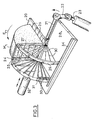
- the apparatus shown in Figure 1 mainly comprises a horizontal table 1 of semi-circular shape intended to support a half of a wheel M of cheese to be cut.
- Table 1 is rotatably mounted on a vertical axis cal concretized by a shaft 2. As shown in FIG. 2, the table 1 is provided with concentric semi-circular slots 3 intended to allow the passage of thin wires or blades 4 in diamond shapes fixed to the frame 5 of the device, in which table 1 is mounted.
- the semi-circular table 1 comprises, disposed along one of its radial edges, a stop plate 5 molded with the plate 1 and in which are formed vertical grooves 7 intended to receive the cutting blades 4 at the end of the stroke the table to ensure the complete cut of the wheel part M.
- the table further comprises retractable stops 7a intended to immobilize the portion of grinding wheel M on the table in order to force it to accompany the table in its rotational movement.
- the frame carries two slides 8, in which a radial blade 9 in the form of a guillotine actuated by a pneumatic cylinder 10 is slidably mounted.
- the radial blade 9 is arranged near the vertical blades 4, practically to the latter.
- a circular drive plate 11 On the support shaft 2 of the table 1 is wedged a circular drive plate 11 at the periphery of which are hooked at regular intervals 12 hooks constituted by sections of vertical rod welded to the edge of the plate.
- the hooks 12, the spacing of which determines the advance pitch of the plate 11 and consequently of the table 1, are intended to cooperate with a spout 13 carried by a lever arm 14 actuated by a pneumatic cylinder 15.
- the arm 14 In order to allow the arm 14 to have a lateral movement to prevent the spout 13 from jamming on the hooks 12 during its return movement, the arm 14 is mounted on a guide shoe 16 articulated on a connecting rod 17 secured to a ring 18 mounted freely on the shaft 2.
- a return spring is intended to bring the shoe into its position of engagement with the spout 13 with a hook 12.
- the apparatus which has just been described operates in the following manner: the half-grinding wheel M is placed on the table 1, so that its cut part is located opposite the thrust plate 6. It is also fixed to table 1 by means of retractable stops 7a.
- the jack 15 is supplied so that the spout 13 engages with a hook 12 of the drive plate and drives said plate in the direction of arrow F in FIG. 1.
- the stroke of the piston of the jack 15 corresponds to the pitch of plate rotation 11.
- the actuator 15 is supplied so that the arm 14 returns to its initial position.
- the spout 13 strikes one of the hooks 12 and is returned by the latter outwards relative to the plate 11, causing the articulated arm to spread apart on the connecting rod 17.
- the return spring not shown, it returns in alignment with the rod of the jack 15 in a position of engagement with the next hook 12.
- the actuator 10 for actuating the guillotine blade 9 is then supplied so that the blade initially in the high position is moved downwards and cuts the portions of crowns cut by the blades 4 so that we obtain portions in the form of sectors.
- the jack 10 is supplied so as to raise it and retract it into the frame 5, which makes it possible to again advance the table 1 by one step and to cut out following crown portions.
- the operations of supplying the jack 10 and 15 are ensured by end-of-travel contacts not shown, associated with the jacks and controlling the opening or closing of air intake valves in said jacks.
- the push plate 6 comes against the blades 4 which each penetrate into one of the grooves 7 of the push-plate 6 so as to ensure the complete cutting of the half-grinding wheel M
- the push plate 6 actuates a contact (not shown) fixed on the frame 5 under the guillotine blade 10 which causes the complete stop of the device.
- the apparatus shown in Figure 3 is intended for cutting quarters of grinding wheels.
- a rectangular table 20 rotatably mounted by one of its sides, around a horizontal axis 21.
- Said axis 21 spins in bearings integral with a frame not shown. It is rotated by a crank 22 driven by a jack 23.
- the table 20 is intended to receive a quarter of a grinding wheel M1 to be cut.
- the apparatus further comprises a vertical frame 24 whose plane passes through the axis of rotation 21 of the table. On this frame are stretched horizontal blades 25 for cutting the wheel portion M1 into portions of concentric crowns.
- the table 20 has parallel grooves 26 in which the blades 25 are intended to be engaged at the end of the travel of the table 20.
- the apparatus of FIG. 3 is completed by a device for cutting the portions of concentric crowns into radial sectors.
- This device comprises, fixed between one of the uprights 27 of the frame 24, and a fixed table 28, a hoop 29 in quarter circumference on which are stretched radial cutting blades 30 arranged at regular intervals.
- a push plate 31 in the form of a quarter of circle is mounted movable in translation on the fixed table 28 under the action of a jack 32.
- the face of the push plate 31 facing the blades 30 has radial grooves 33 intended to receive the radial blades 30 at the end of the stroke of the push plate 31.
- the thrust plate 31 is guided in its movements by the vertical frame 24 carrying the horizontal blades 25 on the one hand and by an external slide 34 fixed to the fixed table 28 on the other hand.
- the operation of the device of Figure 3 is as follows. After placing on the table 20 the quarter wheel M1 to be cut, the jack 23 is fed so as to rotate the table 20 in the direction of the arrow F1.
- the jack 32 is fed, which moves the thrust plate 31. This pushes the quarter wheel cut into portions of crowns on the radial blades 30 which cut the quarter wheel into radial sectors whose size is determined by l 'angle between the radial blades 30.
- the cylinders 23 and 32 are controlled by limit switches.
- the portions of concentric crowns are obtained by moving the portion of cheese wheel relative to a series of blades.
- the apparatus according to the invention makes it possible to pack, in shrink wrap, the parts obtained.
- the cut wheel can also be reconstituted either entirely or in sectors and overwrapped under vacuum or neutral gas, which makes it possible to present it, ready for sale, with the appearance of being not cut into parts.
- the invention by its originality, makes it possible to obtain portions in crown sectors, of shape clearly different from the conventional parallelepipedic shape, from where a better presentation of the portions and a great regularity of quality.
Landscapes
- Life Sciences & Earth Sciences (AREA)
- Forests & Forestry (AREA)
- Engineering & Computer Science (AREA)
- Mechanical Engineering (AREA)
- Dairy Products (AREA)
- Finish Polishing, Edge Sharpening, And Grinding By Specific Grinding Devices (AREA)
- Treatment Of Fiber Materials (AREA)
Claims (12)
Priority Applications (3)
| Application Number | Priority Date | Filing Date | Title |
|---|---|---|---|
| DE8282400782T DE3272002D1 (en) | 1982-04-29 | 1982-04-29 | Method and apparatus for cutting wheels of cheese into small pieces, in particular of emmentaler |
| EP82400782A EP0093217B1 (de) | 1982-04-29 | 1982-04-29 | Verfahren und Vorrichtung zum Zerschneiden von runden Käse, insbesondere von Emmentaler Käse |
| AT82400782T ATE20711T1 (de) | 1982-04-29 | 1982-04-29 | Verfahren und vorrichtung zum zerschneiden von runden kaese, insbesondere von emmentaler kaese. |
Applications Claiming Priority (1)
| Application Number | Priority Date | Filing Date | Title |
|---|---|---|---|
| EP82400782A EP0093217B1 (de) | 1982-04-29 | 1982-04-29 | Verfahren und Vorrichtung zum Zerschneiden von runden Käse, insbesondere von Emmentaler Käse |
Publications (2)
| Publication Number | Publication Date |
|---|---|
| EP0093217A1 EP0093217A1 (de) | 1983-11-09 |
| EP0093217B1 true EP0093217B1 (de) | 1986-07-16 |
Family
ID=8189906
Family Applications (1)
| Application Number | Title | Priority Date | Filing Date |
|---|---|---|---|
| EP82400782A Expired EP0093217B1 (de) | 1982-04-29 | 1982-04-29 | Verfahren und Vorrichtung zum Zerschneiden von runden Käse, insbesondere von Emmentaler Käse |
Country Status (3)
| Country | Link |
|---|---|
| EP (1) | EP0093217B1 (de) |
| AT (1) | ATE20711T1 (de) |
| DE (1) | DE3272002D1 (de) |
Families Citing this family (7)
| Publication number | Priority date | Publication date | Assignee | Title |
|---|---|---|---|---|
| NL8700126A (nl) * | 1987-01-20 | 1988-08-16 | Dmv Campina Bv | Werkwijze en inrichting voor het snijden van kaas in plakken, alsmede plakken verkregen onder toepassing van deze werkwijze. |
| FR2766404B1 (fr) * | 1997-07-24 | 1999-10-01 | Entremont | Procede pour la decoupe de meules de fromage, installation et dispositif pour sa mise en oeuvre |
| FR2939349B1 (fr) * | 2008-12-05 | 2012-07-06 | Ermatec | Machine de decoupe de produit agro alimentaire |
| NL2003091C2 (en) | 2009-06-26 | 2010-06-16 | Westland Kaas Groep B V | Piece of cheese cut from a block, such as a wheel, brick, or ball, and method of and apparatus for preparing the same. |
| FR3048372B1 (fr) * | 2016-03-01 | 2018-03-30 | Bfr Systems | Dispositif pour la decoupe en tranches radiales de produits alimentaires |
| WO2018167754A2 (es) * | 2018-06-14 | 2018-09-20 | Universidad Técnica Particular De Loja | Dispositivo cortador de alimentos sin hueso |
| IT201800006632A1 (it) * | 2018-06-25 | 2019-12-25 | Procedimento per confezionare un formaggio a pasta dura e relativa confezione |
Family Cites Families (8)
| Publication number | Priority date | Publication date | Assignee | Title |
|---|---|---|---|---|
| FR744702A (de) * | 1933-04-26 | |||
| FR425236A (fr) * | 1911-01-25 | 1911-06-06 | Carl Klautschke | Appareil à couper le fromage |
| FR556411A (fr) * | 1921-09-23 | 1923-07-20 | Machine à diviser les fruits et tubercules, notamment les pommes de terre | |
| US1560090A (en) * | 1924-08-19 | 1925-11-03 | Alfred W Green | Cheese cutter |
| FR1332636A (fr) * | 1962-06-05 | 1963-07-19 | Machine à couper le fromage | |
| US3132423A (en) * | 1962-06-22 | 1964-05-12 | Lano Artus D De | Food cutting apparatus |
| US3921480A (en) * | 1974-09-12 | 1975-11-25 | Rohr Industries Inc | Form generator for cellular materials |
| DE2915997A1 (de) * | 1979-04-20 | 1980-11-13 | Fred T Hudema | Geraet zum schneiden, wuerfeln und schnitzeln von fruechten und gemuesen |
-
1982
- 1982-04-29 DE DE8282400782T patent/DE3272002D1/de not_active Expired
- 1982-04-29 AT AT82400782T patent/ATE20711T1/de not_active IP Right Cessation
- 1982-04-29 EP EP82400782A patent/EP0093217B1/de not_active Expired
Also Published As
| Publication number | Publication date |
|---|---|
| DE3272002D1 (en) | 1986-08-21 |
| EP0093217A1 (de) | 1983-11-09 |
| ATE20711T1 (de) | 1986-08-15 |
Similar Documents
| Publication | Publication Date | Title |
|---|---|---|
| EP0253719B1 (de) | Einfüllschacht an einer Maschine zum Behandeln von Nahrungsmitteln | |
| CH438688A (fr) | Machine à mouler des flacons en matière thermoplastique | |
| EP0113637B2 (de) | Maschine zur automatischen Herstellung von Fleisch-, Gemüse oder anderen Spiessen | |
| EP0929383B1 (de) | Maschine zum auf genaues mass zerkleinern von nahrungsmitteln | |
| CH631606A5 (fr) | Procede de preparation d'un produit alimentaire, machine pour la mise en oeuvre du procede et produit alimentaire obtenu par le procede. | |
| EP0331634B1 (de) | Verfahren und Apparat für das Öffnen einer Papierbandspule | |
| EP0469976B1 (de) | Verfahren und automatische Vorrichtung zur Herstellung kalibrierter Ringe aus profiliertem oder unprofiliertem Extrudat | |
| EP0093217A1 (de) | Verfahren und Vorrichtung zum Zerschneiden von runden Käse, insbesondere von Emmentaler Käse | |
| EP0015194B1 (de) | Verfahren und Vorrichtung zum Formen von Teigmengen | |
| FR2527971A1 (fr) | Procede et appareil pour ebarber un objet plat en ceramique | |
| EP0469972B1 (de) | Vorrichtung zum Bedecken einer horizontalen Oberfläche, wie eines Backbleches mit einem fliessfähigen Teig, insbesondere eines ungekochten essbaren Teiges | |
| FR2503013A1 (fr) | Procede et appareil pour la decoupe de meules rondes de fromage, notamment d'emmental | |
| FR2498979A1 (fr) | Procede de fabrication de longerons de pale d'helicoptere | |
| FR2535169A1 (fr) | Procede et machine pour la confection industrielle de brochettes de viande | |
| FR2939349A1 (fr) | Machine de decoupe de produit agro alimentaire | |
| CH379380A (fr) | Machine à mouler et emballer en tranches une matière semi-pâteuse, telle par exemple que du fromage fondu | |
| US20070084324A1 (en) | Slicer for circular formed bakery products | |
| FR2592856A3 (fr) | Machine pour la confection et l'emballage automatiques de biftecks haches | |
| EP0014135B1 (de) | Vorrichtungen zum in Scheiben schneiden von Lachs | |
| FR2645065A1 (fr) | Procede pour trancher en secteurs un produit alimentaire, notamment du type fromage et le dispositif de mise en oeuvre | |
| FR2614763A1 (fr) | Dispositif pour realiser une enveloppe en boyau naturel pour la fabrication des saucissons | |
| FR2882677A1 (fr) | Machine de decoupe de produits agroalimentaires. | |
| EP0893213A1 (de) | Verfahren zum Schneiden von Käselaiben, sowie Anlage und Vorrichtung zur Durchführung des Verfahrens | |
| FR2851886A1 (fr) | Machine de decoupe de produits agroalimentaires | |
| EP3213891B1 (de) | Vorrichtung zum schneiden von lebensmittelprodukten in radiale scheiben |
Legal Events
| Date | Code | Title | Description |
|---|---|---|---|
| PUAI | Public reference made under article 153(3) epc to a published international application that has entered the european phase |
Free format text: ORIGINAL CODE: 0009012 |
|
| AK | Designated contracting states |
Designated state(s): AT CH DE FR IT LI |
|
| 17P | Request for examination filed |
Effective date: 19830930 |
|
| RAP1 | Party data changed (applicant data changed or rights of an application transferred) |
Owner name: DELTEIL, URBAIN |
|
| GRAA | (expected) grant |
Free format text: ORIGINAL CODE: 0009210 |
|
| AK | Designated contracting states |
Kind code of ref document: B1 Designated state(s): AT CH DE FR IT LI |
|
| REF | Corresponds to: |
Ref document number: 20711 Country of ref document: AT Date of ref document: 19860815 Kind code of ref document: T |
|
| REF | Corresponds to: |
Ref document number: 3272002 Country of ref document: DE Date of ref document: 19860821 |
|
| ITF | It: translation for a ep patent filed | ||
| PLBE | No opposition filed within time limit |
Free format text: ORIGINAL CODE: 0009261 |
|
| STAA | Information on the status of an ep patent application or granted ep patent |
Free format text: STATUS: NO OPPOSITION FILED WITHIN TIME LIMIT |
|
| 26N | No opposition filed | ||
| PGFP | Annual fee paid to national office [announced via postgrant information from national office to epo] |
Ref country code: FR Payment date: 19900412 Year of fee payment: 9 |
|
| PGFP | Annual fee paid to national office [announced via postgrant information from national office to epo] |
Ref country code: CH Payment date: 19900425 Year of fee payment: 9 |
|
| PGFP | Annual fee paid to national office [announced via postgrant information from national office to epo] |
Ref country code: DE Payment date: 19900426 Year of fee payment: 9 |
|
| PGFP | Annual fee paid to national office [announced via postgrant information from national office to epo] |
Ref country code: AT Payment date: 19900427 Year of fee payment: 9 |
|
| ITTA | It: last paid annual fee | ||
| PG25 | Lapsed in a contracting state [announced via postgrant information from national office to epo] |
Ref country code: AT Effective date: 19910429 |
|
| PG25 | Lapsed in a contracting state [announced via postgrant information from national office to epo] |
Ref country code: LI Effective date: 19910430 Ref country code: CH Effective date: 19910430 |
|
| PG25 | Lapsed in a contracting state [announced via postgrant information from national office to epo] |
Ref country code: FR Effective date: 19911230 |
|
| REG | Reference to a national code |
Ref country code: CH Ref legal event code: PL |
|
| PG25 | Lapsed in a contracting state [announced via postgrant information from national office to epo] |
Ref country code: DE Effective date: 19920201 |
|
| REG | Reference to a national code |
Ref country code: FR Ref legal event code: ST |