EP0093226A2 - Fournisseur de fils en particulier fils métalliques par tirage à partir d'une bobine - Google Patents
Fournisseur de fils en particulier fils métalliques par tirage à partir d'une bobine Download PDFInfo
- Publication number
- EP0093226A2 EP0093226A2 EP83100732A EP83100732A EP0093226A2 EP 0093226 A2 EP0093226 A2 EP 0093226A2 EP 83100732 A EP83100732 A EP 83100732A EP 83100732 A EP83100732 A EP 83100732A EP 0093226 A2 EP0093226 A2 EP 0093226A2
- Authority
- EP
- European Patent Office
- Prior art keywords
- thread
- friction wheel
- unwound
- deflection roller
- spool
- Prior art date
- Legal status (The legal status is an assumption and is not a legal conclusion. Google has not performed a legal analysis and makes no representation as to the accuracy of the status listed.)
- Withdrawn
Links
Images


Classifications
-
- B—PERFORMING OPERATIONS; TRANSPORTING
- B65—CONVEYING; PACKING; STORING; HANDLING THIN OR FILAMENTARY MATERIAL
- B65H—HANDLING THIN OR FILAMENTARY MATERIAL, e.g. SHEETS, WEBS, CABLES
- B65H51/00—Forwarding filamentary material
- B65H51/20—Devices for temporarily storing filamentary material during forwarding, e.g. for buffer storage
Definitions
- the invention relates to a device according to the preamble of claim 1.
- Delivery devices for running threads are known on the market which have a drum-like storage body. A corresponding length of thread supply is applied to this, which thread is then drawn off from the drum-like storage body in the axial direction.
- Such a device is not very suitable for the delivery of, in particular, metallic threads, monofilaments or ribbons, since there is a rotation difference of one rotation for each turn removed from the storage body.
- this spiral spring effect proves to be disruptive in the further processing of the aforementioned threads, for example on a weaving machine.
- the object of the invention is based on the object of designing a device of the presupposed type in such a way that, on the one hand, metallic threads, monofilaments and ribbons, in particular, pass through and are released from the device without twisting and that, on the other hand, high, suddenly occurring thread pull-off tensions can be compensated.
- a generic device of increased utility value is specified.
- the thread runs through the device without drilling while avoiding the undesired spiral spring effect. This is achieved in that the thread is unwound from the thread spool in a tangential direction, that is to say without twisting, by the friction wheel resting on the outer thread layer. Specifically, this means that the peripheral speed of the friction wheel corresponds to the thread speed.
- the thread then arrives at the thread buffer. Its thread deflection rollers, which can be moved on vertical rails and are moved in a pulley-like manner, save a certain length of thread, but again without twisting.
- the second thread deflecting roller which is movable opposite to the thread deflecting roller that tightens the unwound thread length, is loaded by individual weights which add up to one another depending on their degree of displacement. This further counteracts suddenly occurring tension peaks in the thread take-off.
- the corresponding thread deflection rollers move in opposite directions, with the individual weights adding together causing increasing damping. After the tension peaks have been released, the individual weights also guide the corresponding thread deflection roller into a position that tightens the unwound thread length, but without undesired spring-back.
- a scanning device controlling the friction wheel drive is provided in the movement path of the deflection roller tightening the unwound thread length. If the deflection roller has moved by a certain amount, this means that a corresponding thread length was required for the take-off. In accordance with this position, the deflection roller tightening the unwound thread length controls the friction wheel drive via the scanning device.
- the friction wheel drive speed can be varied depending on the position of the deflecting roller which tightens the unwound thread length, in accordance with the required thread requirement.
- the friction wheel drive can be brought into and out of action in a simple manner in that the friction wheel drive and the equalization drum are arranged in a frame which can be pivoted against the thread spool, the pivotability of which maintains the contact position between the friction wheel and the outer thread position. This allows easy replacement of the thread spool. For this purpose, only the frame with the friction wheel has to be pivoted.
- the thread deflection roller tightening the unwound thread length is designed as a multiple roller.
- thread deflection roller tightening the unwound thread length can be loaded with different additional weights.
- a variant of the invention is that the second thread deflection roller is spring-loaded in the opposite direction to the force of gravity of the thread deflection roller tightening the unwound thread length.
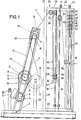
- the device has a base frame 1. This supports a frame 3 in its front section about a horizontal axis 2.
- the latter carries a controllable drive motor 4 with a pulley 5 in its lower region.
- Above the drive motor 4 sits on one of bearings 6 of the frame 3 supported shaft 7 rotatably a friction wheel 8.
- the end of the horizontally oriented shaft 7 projecting beyond the frame carries a pulley 9.
- a belt 10 is placed around this and around the pulley 5. In the immediate vicinity of the pulley 9 there is a further pulley 11 on the shaft 7.
- the belt 12 placed around this displaces one Pulley 13 in rotation, which in turn is attached to a shaft 14.
- the latter is arranged in the upper region of the frame 3 and passes through a bearing 15 of the frame.
- the inboard end of the shaft 14 receives an equalization drum 16.
- the friction wheel 8 lies on the outer thread layer 17 of a thread spool 18. This is carried by centering pins 19, which start from vertical columns 20 of the base frame 1. If the frame 3 is pivoted in the direction of the thread spool 18, then it exceeds the vertical position and is in contact with the outer thread layer 17 due to gravity with the friction wheel 8. The friction wheel 8 can be disengaged by pivoting the frame 3 in the opposite direction. A vertical arm 21 of the base frame then serves with a roller 22 as a limit stop for the frame 3. This position is suitable for the insertion or replacement of the thread spool 18.
- the thread F unwound from the thread spool 18 passes through a thread eyelet 23 arranged upstream of the equalization drum 16 and attached to the frame 3. Coming from there, it loops around the equalization drum 16 several times in such a way that the thread windings applied to it lie in a slip-free manner to the compensating drum.
- the thread F is drawn off from the equalization drum 16 in the tangential direction and passes through a thread eyelet 24 of the frame 3.
- the thread F then arrives at a thread buffer store 25.
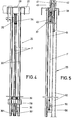
- the thread buffer has the frame structure 26 starting from the base frame 1.
- An upper crosspiece 27 of the same carries a rearward, horizontally extending central arm 28. This is opposite a horizontal arm 29 directly attached to the base frame 1.
- the arms 28, 29 carry vertical rails 30, 31 between them, which are in pairs are arranged. Between the free rear ends of the arms 28, 29 there are provided supports 32 which are arranged parallel to one another and which accommodate guide rods 33 between them.
- the intermediate store 25 contains thread deflecting rollers 34 and 35 which are mounted in a stationary manner on the upper arm 28. Furthermore, it has the thread deflecting rollers 36, 37 which are guided on the vertical rails 30, 31 and can be moved in a pulley-like manner.
- the lower thread deflection roller 36 is designed as a multiple roller in that it is composed of two individual rollers 36 'and 36 ". The individual rollers 36', 36" are carried by a sliding shoe 38 which can be displaced on the rails 30. The latter can take up additional weights 39 on its upper side .
- the thread F leaving the equalization drum 16 initially wraps around the deflection roller 34. From there it arrives at the individual roller 36 ', from where it runs to the deflection roller 35 and wraps around it.
- Fig. 4 illustrates that the deflection rollers 34, 35 lie on two adjacent planes to each other according to the distance of the individual rollers 36 'and 36 "from each other.
- the thread arrives at the individual roller 36" of the deflection roller 36, from where it leads to Thread deflection roller 37 is guided.
- the latter is mounted in a slide shoe 40 which is arranged such that it can be moved on the rails 31.
- a cable 43 deflected by rollers 41, 42 acts on the upper end of the sliding shoe 40.
- the free end 43 'of this cable pull 43 runs between the guide rods 33 and carries there an individual weight 44 penetrated by the guide rods 33.
- the thread F coming from the deflecting roller 37 wraps around a deflecting roller 55 which is fastened to the one support 32. From there, the thread leaves the device via a thread eyelet 56.
- both the deflection roller 36 tightening the drawn-off thread length, consisting of the two individual rollers 36 'and 36 ", and the opposite thread deflection roller 37 are displaced while damping the increase in tension.
- the upper deflection roller 37 is displaced, the sum of the displacements increases according to the amount of displacement Individual weights, as illustrated in Fig. 1.
- scanning devices 57, 58, 59, 60 which control the friction wheel drive speed, are provided in the movement path of the deflection roller 36 which tightens the unwound thread length the area of the scanning device 60, this means that a longer thread length was required and that consequently the friction wheel drive operates at a higher speed in order to supply sufficient thread length.
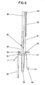
- the thread deflection roller 37 is not loaded by individual weights which add up.
- a cable pull 61 which is connected to one end of a tension spring 62, now acts on the thread deflection roller 37. Its other end 62 "starts from a telescopic shoe 65. This runs on a vertical column 63 projecting above the upper arm 28 and can be adjusted by means of the clamping screw 64 in order to be able to exert different loads on the deflection roller 37. Due to the length of the cable 61 the possibility of movement of the thread deflection roller 37 is limited and the wobbling of the tension spring when the thread deflection roller 37 has reached the normal position is avoided. If necessary, it is also possible to mount the tension spring 62 and the telescopic shoe 65 in a horizontal orientation.
Landscapes
- Tension Adjustment In Filamentary Materials (AREA)
- Forwarding And Storing Of Filamentary Material (AREA)
Applications Claiming Priority (2)
| Application Number | Priority Date | Filing Date | Title |
|---|---|---|---|
| DE3216605 | 1982-05-04 | ||
| DE3216605 | 1982-05-04 |
Publications (2)
| Publication Number | Publication Date |
|---|---|
| EP0093226A2 true EP0093226A2 (fr) | 1983-11-09 |
| EP0093226A3 EP0093226A3 (fr) | 1985-09-18 |
Family
ID=6162645
Family Applications (1)
| Application Number | Title | Priority Date | Filing Date |
|---|---|---|---|
| EP83100732A Withdrawn EP0093226A3 (fr) | 1982-05-04 | 1983-01-27 | Fournisseur de fils en particulier fils métalliques par tirage à partir d'une bobine |
Country Status (1)
| Country | Link |
|---|---|
| EP (1) | EP0093226A3 (fr) |
Cited By (3)
| Publication number | Priority date | Publication date | Assignee | Title |
|---|---|---|---|---|
| EP0287802A3 (fr) * | 1987-04-23 | 1990-08-01 | STATOMAT-GLOBE Machinenfabrik GmbH | Dispositif pour alimenter du câble d'une bobine débitrice vers une machine de fabrication de câble |
| DE102005015528A1 (de) * | 2005-04-04 | 2006-10-05 | Josef Soller | Vorrichtung, insbesondere zum Befestigen von Steigdrähten am Spanndraht in Hopfengärten |
| CN102295188A (zh) * | 2011-05-27 | 2011-12-28 | 常州市第八纺织机械有限公司 | 复合材料生产线的储纱机构 |
Family Cites Families (12)
| Publication number | Priority date | Publication date | Assignee | Title |
|---|---|---|---|---|
| US3289959A (en) * | 1966-12-06 | Material feed control device | ||
| DE449957C (de) * | 1925-02-04 | 1927-10-03 | Carl Christian Erdmann | Aufspulvorrichtung, insbesondere fuer sehr feine Draehte und Faeden, mit selbsttaetiger Einschaltung einer Antriebsvorrichtung fuer die Ablaufspule |
| US2141934A (en) * | 1936-04-18 | 1938-12-27 | Waterbury Farrel Foundry & Mac | Belt driven wire spooler |
| US2594427A (en) * | 1947-05-22 | 1952-04-29 | Western Electric Co | Method and apparatus for uniformly tensioning an advancing strand |
| US2560204A (en) * | 1947-06-17 | 1951-07-10 | Artos Engineering Co | Automatic strand feed regulator |
| US3022812A (en) * | 1957-02-21 | 1962-02-27 | Alvin F Groll | Feed control means |
| US2929569A (en) * | 1957-02-26 | 1960-03-22 | Western Electric Co | Continuous wire winding apparatus |
| US2996263A (en) * | 1957-07-01 | 1961-08-15 | B B Chem Co | Winding machine |
| FR1358595A (fr) * | 1963-03-07 | 1964-04-17 | Geoffroy Delore | Câbleuse à bobines de départ donneuses et à entraînement avec glissement du tambour de réception |
| US3334838A (en) * | 1964-09-05 | 1967-08-08 | Kopp & Odenwald | Apparatus for feeding wound material to a processing machine |
| US3501075A (en) * | 1967-11-28 | 1970-03-17 | Herbert D Scharf | Wire tension control device |
| BE788480A (fr) * | 1971-09-23 | 1973-03-06 | Rieter Ag Maschf | Dispositif d'envidage avec changement automatique de bobine et moyens pour la compensation des variations de tension du fil au changement de bobine |
-
1983
- 1983-01-27 EP EP83100732A patent/EP0093226A3/fr not_active Withdrawn
Cited By (5)
| Publication number | Priority date | Publication date | Assignee | Title |
|---|---|---|---|---|
| EP0287802A3 (fr) * | 1987-04-23 | 1990-08-01 | STATOMAT-GLOBE Machinenfabrik GmbH | Dispositif pour alimenter du câble d'une bobine débitrice vers une machine de fabrication de câble |
| DE102005015528A1 (de) * | 2005-04-04 | 2006-10-05 | Josef Soller | Vorrichtung, insbesondere zum Befestigen von Steigdrähten am Spanndraht in Hopfengärten |
| DE102005015528A9 (de) * | 2005-04-04 | 2007-02-01 | Josef Soller | Vorrichtung, insbesondere zum Befestigen von Steigdrähten am Spanndraht in Hopfengärten |
| CN102295188A (zh) * | 2011-05-27 | 2011-12-28 | 常州市第八纺织机械有限公司 | 复合材料生产线的储纱机构 |
| CN102295188B (zh) * | 2011-05-27 | 2013-07-10 | 常州市第八纺织机械有限公司 | 复合材料生产线的储纱机构 |
Also Published As
| Publication number | Publication date |
|---|---|
| EP0093226A3 (fr) | 1985-09-18 |
Similar Documents
| Publication | Publication Date | Title |
|---|---|---|
| DE4324412C2 (de) | Vorrichtung zur Einstellung der Fadenspannung | |
| DE68901699T2 (de) | Streifenabgabevorrichtung. | |
| DE3233869C2 (de) | Vorrichtung zum Zuliefern von elastomeren Fäden, insbesondere für Strick- und Wirkmaschinen | |
| CH694370A5 (de) | Aufspulvorrichtung. | |
| CH649065A5 (de) | Vorrichtung zum aufspulen eines garnes auf eine garnspule. | |
| DE2132416A1 (de) | Vorrichtung zur kontinuierlichen Herstellung von Bewehrungen | |
| EP3555352A1 (fr) | Bobine débitrice de fil à friction | |
| DE2650590C2 (de) | Verfahren und Vorrichtung zum Herstellen einer Geflechtrolle | |
| DE29723957U1 (de) | Aufspulmaschine zum Aufspulen eines mit konstanter Geschwindigkeit anlaufenden Fadens | |
| EP0093226A2 (fr) | Fournisseur de fils en particulier fils métalliques par tirage à partir d'une bobine | |
| DE3046003A1 (de) | Selbsttaetige garnzufuehrung fuer rundstrick- oder wirkmaschinen | |
| WO1999041180A1 (fr) | Dispositif de bobinage | |
| DE2635200C2 (de) | Fadenzuführeinrichtung | |
| CH638159A5 (de) | Vorrichtung zum abziehen, speichern und ablegen von endlosem filament-, strang- oder kabelmaterial. | |
| DE4139583A1 (de) | Kettfadenzufuehrung fuer webmaschinen | |
| CH382617A (de) | Vorrichtung zur Konstanthaltung der Zugspannung des Wickelgutes bei veränderlicher Abzugsgeschwindigkeit für Wickel- und Spulmaschinen | |
| DE2538819C3 (de) | Wickelmaschine zum Herstellen einer schraubenwendelförmigen Reißverschlußgliederreihe aus einem Kunststoffdraht | |
| DE1221937B (de) | Ausgleichsvorrichtung fuer den Fadenabzug von mehreren frei drehbaren Spulen, insbesondere bei Doppeldrahtzwirnmaschinen | |
| DE2727813C2 (de) | Vorrichtung zum Abspulen von Schweißdraht | |
| DE3817679C1 (en) | Cabling machine | |
| CH620720A5 (fr) | ||
| DE2402055A1 (de) | Einrichtung zum naehen bzw. heften von baendern | |
| CH346146A (de) | Spulmaschine mit Geschwindigkeitsregler | |
| DE1925818B2 (de) | Vorrichtung zum Umspulen von Glasfäden | |
| DE2431691C2 (de) | Maschine zum kontinuierlichen Aufwickeln einer Warenbahn |
Legal Events
| Date | Code | Title | Description |
|---|---|---|---|
| PUAI | Public reference made under article 153(3) epc to a published international application that has entered the european phase |
Free format text: ORIGINAL CODE: 0009012 |
|
| AK | Designated contracting states |
Designated state(s): AT BE CH DE FR GB IT LI LU NL SE |
|
| PUAL | Search report despatched |
Free format text: ORIGINAL CODE: 0009013 |
|
| AK | Designated contracting states |
Designated state(s): AT BE CH DE FR GB IT LI LU NL SE |
|
| STAA | Information on the status of an ep patent application or granted ep patent |
Free format text: STATUS: THE APPLICATION IS DEEMED TO BE WITHDRAWN |
|
| 18D | Application deemed to be withdrawn |
Effective date: 19850801 |