EP0093236A2 - Fiche pour appareil - Google Patents
Fiche pour appareil Download PDFInfo
- Publication number
- EP0093236A2 EP0093236A2 EP83101494A EP83101494A EP0093236A2 EP 0093236 A2 EP0093236 A2 EP 0093236A2 EP 83101494 A EP83101494 A EP 83101494A EP 83101494 A EP83101494 A EP 83101494A EP 0093236 A2 EP0093236 A2 EP 0093236A2
- Authority
- EP
- European Patent Office
- Prior art keywords
- locking tab
- plug
- housing
- carrier element
- connector
- Prior art date
- Legal status (The legal status is an assumption and is not a legal conclusion. Google has not performed a legal analysis and makes no representation as to the accuracy of the status listed.)
- Granted
Links
Images

Classifications
-
- H—ELECTRICITY
- H01—ELECTRIC ELEMENTS
- H01R—ELECTRICALLY-CONDUCTIVE CONNECTIONS; STRUCTURAL ASSOCIATIONS OF A PLURALITY OF MUTUALLY-INSULATED ELECTRICAL CONNECTING ELEMENTS; COUPLING DEVICES; CURRENT COLLECTORS
- H01R13/00—Details of coupling devices of the kinds covered by groups H01R12/70 or H01R24/00 - H01R33/00
- H01R13/73—Means for mounting coupling parts to apparatus or structures, e.g. to a wall
- H01R13/74—Means for mounting coupling parts in openings of a panel
- H01R13/741—Means for mounting coupling parts in openings of a panel using snap fastening means
- H01R13/743—Means for mounting coupling parts in openings of a panel using snap fastening means integral with the housing
-
- H—ELECTRICITY
- H01—ELECTRIC ELEMENTS
- H01R—ELECTRICALLY-CONDUCTIVE CONNECTIONS; STRUCTURAL ASSOCIATIONS OF A PLURALITY OF MUTUALLY-INSULATED ELECTRICAL CONNECTING ELEMENTS; COUPLING DEVICES; CURRENT COLLECTORS
- H01R13/00—Details of coupling devices of the kinds covered by groups H01R12/70 or H01R24/00 - H01R33/00
- H01R13/73—Means for mounting coupling parts to apparatus or structures, e.g. to a wall
- H01R13/74—Means for mounting coupling parts in openings of a panel
-
- H—ELECTRICITY
- H01—ELECTRIC ELEMENTS
- H01R—ELECTRICALLY-CONDUCTIVE CONNECTIONS; STRUCTURAL ASSOCIATIONS OF A PLURALITY OF MUTUALLY-INSULATED ELECTRICAL CONNECTING ELEMENTS; COUPLING DEVICES; CURRENT COLLECTORS
- H01R13/00—Details of coupling devices of the kinds covered by groups H01R12/70 or H01R24/00 - H01R33/00
- H01R13/62—Means for facilitating engagement or disengagement of coupling parts or for holding them in engagement
- H01R13/627—Snap or like fastening
Definitions
- the invention relates to a device plug for the electrical connection of a telecommunication cord to a communications device with a plug element on which an outwardly projecting, resilient locking tab is formed, which enables a latching lock with the device.
- locking tabs projecting from a side surface, in which the locking tab springs behind a locking edge, for example the housing wall of the device, with a projection.
- the locking tabs can be designed (DE-AS 24 32 122) that this locking is released by manual actuation of the locking tab or so (DE-GM 80 01 874) - that the locking lock only with the aid of a tool, for example a screwdriver, can be solved again.
- a disadvantage of these known device plugs is that the security with which the device plugs are held in their locked position in the devices are relatively low, since the locking tabs which protrude freely on one side and which are usually made of the same plastic material as the device plugs and are made in one piece with these, can be moved from their locking position with relatively low forces. The consequence of this is that the locking of the device connector easily loosens or releases when shaken.
- the invention has for its object to design a device connector so that a relatively large holding security is achieved in the locking position with simple means.
- the invention is that the locking tab is designed as a spring tongue fixedly connected to the plug carrier element, which runs at a distance from the outer surface of the plug carrier element, is supported with its free end on a counter bearing and engages under an edge that at one on the Plug carrier element mounted part is provided opposite the counter bearing.
- the free end of the locking tab is held under prestress on the edge designed as a stop edge.
- the free end lies in the direction of the outer surface on the counter bearing, so that the unlocking is determined by the force that is required to bend the locking tab.
- the free end of the locking tab cannot swing freely. The unlocking force also increases.
- the part placed on the plug carrier element consists of a two-shell plug housing provided with the stop edge, from which the plug carrier element projects forward with a contact area.
- the locking tab initially protrudes from the plug carrier element and is pressed and pretensioned by the fastening in a housing of housing parts at the free end in the direction of the outer surface from which it projects.
- a recess for the locking tab is formed in the plug housing, from which the locking tab protrudes with a surface that rises away from the contact area and forms a latching protrusion that ends approximately half the length of the locking tab.
- the rising surface makes it easier to insert it, with the locking tab then being bent when the device plug is inserted and springing back into its pretensioned starting position after the plugging in. A vibration-free hold is thereby achieved in particular because of the relatively large bending stress.
- the connector housing has a step-like extension at least on the side assigned to the locking tab, while leaving a distance from the locking device corresponding to a wall thickness in the region of the insertion opening of the communications technology device, by means of which the insertion depth of the connector is limited.
- the distance between the latching hook and the extended area of the housing is selected so that it is a wall thickness of the device in the area of a slide opening corresponds, the connector snaps in such a way that it does not give way under pressure or under tension and is firmly seated in the insertion opening.
- the cutout for the locking tab extends into the extended housing area and if the locking tab runs in the direction of the cord-side end of the device plug and beyond the end edge of the cutout forming the stop edge and is prestressed by it.
- an opening is created in the area outside the device in the inserted position of the device plug, through which the locking tab, for example with a screwdriver or the like. is accessible so that the locking lock can be released again.
- the free end can be easily determined in the sense that it is not flexible with respect to the outer surface plane of the plug carrier element, but instead is firmly clamped in the connector housing.
- the device plug is rectangular in cross section and has the locking tab on one end face and if the connector housing is provided on the other end face with a corresponding extension as on the locking tab side.
- a two-sided stop is formed when the device plug is inserted, and moreover the larger areas of the plug carrier element for receiving contact tracks or the like remain. free.
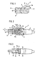
- a plug carrier element is generally designated 1, which is part of a connector 4, as will be explained in FIGS. 2 to 5.
- the connector carrier element 1 is made of plastic material and, as can also be seen from the other figures, has a rectangular cross-sectional shape, with contact tracks 10 being arranged on both sides on the larger side surfaces, which enable contacts in a telecommunications device when the connector carrier element 1 is connected to it Contact area 9 is inserted into a corresponding socket, which is not shown, of such a device.
- a locking tab 2 which is made in one piece with the plug carrier element 1, protrudes from an end-side outer surface 20 at an acute angle ⁇ to the outer surface plane A-A and has a latching hook 8 which enables the latching or locking in a manner described below.
- the plug carrier element 1 is accommodated in a housing 3, which consists of the two half-shells 3a and 3b is formed.
- the contact area 9 protrudes forward from this housing 3.
- a telecommunications cord 5 is received in the housing at the cord-side end via a cord grommet 6 in a manner known per se.
- the housing 3 for the locking tab 2 has a recess 13 on one end face, over which the locking tab 2 protrudes with a surface 7 rising towards the cord-side end, the surface below Formation of the Hökers 8 ends about half the length of the locking tab.
- the housing walls 3c lying to the side of the locking tab 2 end approximately at the level of the line K shown in dashed lines in FIG. 2 and merge into an expanded housing area to form a step-like extension 11a.
- the recess 13 is also continued in the expanded area of the housing with a section 13a (see FIG. 3) and is delimited by the stop edge 12.
- the length of the locking tab 2 is dimensioned such that it extends with its free end 2a, on which it has a block-like shoulder 15, towards the cord-side end of the housing under this stop edge 12.
- the locking tab 2 is pressed by this stop edge 12 towards the outer surface 20 and held in a position in which it runs approximately parallel and at a distance a from this outer surface 20.
- the block-like shoulder 15 is seated on a counter bearing 16 formed on the housing, so that the free end is firmly clamped over the shoulder 15.
- the two half-shells of the housing are connected to one another via hollow rivets 14.
- the locking tab 2 When the device plug 4 is inserted into a housing opening (cf. FIG. 4), the locking tab 2 is gradually bent through the wall 18 in which the insertion opening for the device plug is formed.
- the distance between the step-like extension 11a and the locking peg 8 delimiting the rising surface 7 is dimensioned such that it has a wall thickness b ent speaks, so that the locking tab 2 then springs out and returns to its original position when the stop 11a and also the stop 11b on the opposite side hit the outside against the housing to limit the insertion depth. This ensures a vibration-free hold, with locking forces being large, so that a reliable hold of the plug is ensured.
- the area 13a of the recess 13 which extends into the enlarged housing part lies in the locked position of the device plug outside the housing wall 15, so that there is the possibility, with a tool, for example a screwdriver 17, through this section 13a onto the tab 2 by pressure act so that it bends and the connector can be unlocked, as shown in Fig. 5. It can also be seen from Fig. 5 that the rear edge 12 of the recess is chamfered, so that the insertion of a tool is easily possible and the unlocking can be effected easily.
Landscapes
- Details Of Connecting Devices For Male And Female Coupling (AREA)
- Input Circuits Of Receivers And Coupling Of Receivers And Audio Equipment (AREA)
- Processing Of Terminals (AREA)
Priority Applications (1)
| Application Number | Priority Date | Filing Date | Title |
|---|---|---|---|
| AT83101494T ATE32398T1 (de) | 1982-05-03 | 1983-02-17 | Geraetestecker. |
Applications Claiming Priority (2)
| Application Number | Priority Date | Filing Date | Title |
|---|---|---|---|
| DE3216494 | 1982-05-03 | ||
| DE19823216494 DE3216494A1 (de) | 1982-05-03 | 1982-05-03 | Geraetestecker |
Publications (3)
| Publication Number | Publication Date |
|---|---|
| EP0093236A2 true EP0093236A2 (fr) | 1983-11-09 |
| EP0093236A3 EP0093236A3 (en) | 1986-08-13 |
| EP0093236B1 EP0093236B1 (fr) | 1988-02-03 |
Family
ID=6162583
Family Applications (1)
| Application Number | Title | Priority Date | Filing Date |
|---|---|---|---|
| EP83101494A Expired EP0093236B1 (fr) | 1982-05-03 | 1983-02-17 | Fiche pour appareil |
Country Status (3)
| Country | Link |
|---|---|
| EP (1) | EP0093236B1 (fr) |
| AT (1) | ATE32398T1 (fr) |
| DE (2) | DE3216494A1 (fr) |
Cited By (3)
| Publication number | Priority date | Publication date | Assignee | Title |
|---|---|---|---|---|
| GB2166302A (en) * | 1984-10-19 | 1986-04-30 | Itw Espana Sa | Connector for mounting in hole in an appliance body |
| EP0465798A1 (fr) * | 1990-07-02 | 1992-01-15 | INTERNATIONAL STANDARD ELECTRIC CORPORATION (a Delaware corporation) | Pièce de montage hermétique pour un montage de connecteur |
| DE4202234C1 (en) * | 1992-01-28 | 1992-11-05 | Paul 4284 Heiden De Ossege | Plug for telecommunications appts. - has V=shaped flexible latching element on top side of tip section allowing secure engagement of plug in socket |
Family Cites Families (6)
| Publication number | Priority date | Publication date | Assignee | Title |
|---|---|---|---|---|
| US2889125A (en) * | 1955-01-31 | 1959-06-02 | Hart Mfg Co | Fastener for retaining casings in panels |
| US3358262A (en) * | 1965-10-14 | 1967-12-12 | Amp Inc | Co-ax patch panel and insulative housing members therefor |
| DE1640411A1 (de) * | 1967-10-31 | 1970-05-27 | Harting Elektro W | Steckverbinder zur Befestigung in Montagewandausschnitten |
| US3639950A (en) * | 1968-09-13 | 1972-02-08 | Itt | Latching device |
| US3860316A (en) * | 1973-07-06 | 1975-01-14 | Western Electric Co | Electrical connecting devices for terminating cords and methods of assembling the devices to cords |
| DE8001874U1 (de) * | 1980-01-25 | 1981-04-30 | Albert Ackermann GmbH & Co, 5270 Gummersbach | Stecker für elektrische Kabel |
-
1982
- 1982-05-03 DE DE19823216494 patent/DE3216494A1/de not_active Withdrawn
-
1983
- 1983-02-17 EP EP83101494A patent/EP0093236B1/fr not_active Expired
- 1983-02-17 AT AT83101494T patent/ATE32398T1/de active
- 1983-02-17 DE DE8383101494T patent/DE3375625D1/de not_active Expired
Cited By (3)
| Publication number | Priority date | Publication date | Assignee | Title |
|---|---|---|---|---|
| GB2166302A (en) * | 1984-10-19 | 1986-04-30 | Itw Espana Sa | Connector for mounting in hole in an appliance body |
| EP0465798A1 (fr) * | 1990-07-02 | 1992-01-15 | INTERNATIONAL STANDARD ELECTRIC CORPORATION (a Delaware corporation) | Pièce de montage hermétique pour un montage de connecteur |
| DE4202234C1 (en) * | 1992-01-28 | 1992-11-05 | Paul 4284 Heiden De Ossege | Plug for telecommunications appts. - has V=shaped flexible latching element on top side of tip section allowing secure engagement of plug in socket |
Also Published As
| Publication number | Publication date |
|---|---|
| EP0093236B1 (fr) | 1988-02-03 |
| EP0093236A3 (en) | 1986-08-13 |
| DE3375625D1 (en) | 1988-03-10 |
| ATE32398T1 (de) | 1988-02-15 |
| DE3216494A1 (de) | 1983-11-03 |
Similar Documents
| Publication | Publication Date | Title |
|---|---|---|
| DE69311012T2 (de) | Elektrischer Verbinder | |
| DE2054201C3 (de) | Zur Verwendung in einem elektrischen Steckverbinder bestimmtes elektrisches Kontaktelement | |
| DE2906021C2 (fr) | ||
| DE69027345T2 (de) | Verstärkte Verbinderverriegelung | |
| DE8713038U1 (de) | Buchsenartiger elektrischer Anschluß | |
| DE202021101250U1 (de) | Verbinder | |
| DE102009058616A1 (de) | Leiterplattensteckverbinder mit Verriegelungsvorrichtung | |
| DE1765441A1 (de) | Anschlussvorrichtung fuer gedruckte Schaltungen | |
| DE3705739C2 (de) | Elektrische Verbinderanordnung | |
| EP0316678A2 (fr) | Dispositif de connexion électrique à pôles multiples | |
| EP0756352A1 (fr) | Connecteur à fiche | |
| DE19638971C2 (de) | Relaissockel | |
| EP0093236B1 (fr) | Fiche pour appareil | |
| DE3408115C2 (de) | Verriegelbare und abdrückbare mehrpolige elektrische Steckverbindung in Rechteckform | |
| DE102005053566A1 (de) | Steckerstift mit Federklemme | |
| DE2644612C3 (de) | Aus Blechmaterial gebogenes Kontaktelement für einen mehrpoligen elektrischen Steckverbinder | |
| DE3516150C2 (de) | Ausziehsicherung für Steckverbindungen | |
| EP1243078B1 (fr) | Appareil electrique pourvu d'un boitier | |
| DE3911696C2 (fr) | ||
| DE19744520C1 (de) | Steckbuchse eines Steckverbinders für Datenübertragungssysteme | |
| DE2558739C2 (de) | Rastende Steckverbindung | |
| DE8212755U1 (de) | Geraetestecker | |
| DE2903877C2 (de) | Gehäuse zur Aufnahme von Batterien | |
| DE202011000750U1 (de) | Steckverbindungsanordnung für elektrische Leiter | |
| EP0994526B1 (fr) | Connecteur et plot pour la connexion d'un haut-parleur |
Legal Events
| Date | Code | Title | Description |
|---|---|---|---|
| PUAI | Public reference made under article 153(3) epc to a published international application that has entered the european phase |
Free format text: ORIGINAL CODE: 0009012 |
|
| AK | Designated contracting states |
Designated state(s): AT BE CH DE FR GB IT LI LU NL SE |
|
| PUAL | Search report despatched |
Free format text: ORIGINAL CODE: 0009013 |
|
| AK | Designated contracting states |
Kind code of ref document: A3 Designated state(s): AT BE CH DE FR GB IT LI LU NL SE |
|
| 17P | Request for examination filed |
Effective date: 19860814 |
|
| 17Q | First examination report despatched |
Effective date: 19870616 |
|
| GRAA | (expected) grant |
Free format text: ORIGINAL CODE: 0009210 |
|
| AK | Designated contracting states |
Kind code of ref document: B1 Designated state(s): AT BE CH DE FR GB IT LI LU NL SE |
|
| REF | Corresponds to: |
Ref document number: 32398 Country of ref document: AT Date of ref document: 19880215 Kind code of ref document: T |
|
| ITF | It: translation for a ep patent filed | ||
| PG25 | Lapsed in a contracting state [announced via postgrant information from national office to epo] |
Ref country code: LU Free format text: LAPSE BECAUSE OF NON-PAYMENT OF DUE FEES Effective date: 19880229 |
|
| GBT | Gb: translation of ep patent filed (gb section 77(6)(a)/1977) | ||
| REF | Corresponds to: |
Ref document number: 3375625 Country of ref document: DE Date of ref document: 19880310 |
|
| ET | Fr: translation filed | ||
| PLBE | No opposition filed within time limit |
Free format text: ORIGINAL CODE: 0009261 |
|
| STAA | Information on the status of an ep patent application or granted ep patent |
Free format text: STATUS: NO OPPOSITION FILED WITHIN TIME LIMIT |
|
| 26N | No opposition filed | ||
| PGFP | Annual fee paid to national office [announced via postgrant information from national office to epo] |
Ref country code: SE Payment date: 19890210 Year of fee payment: 7 |
|
| PGFP | Annual fee paid to national office [announced via postgrant information from national office to epo] |
Ref country code: AT Payment date: 19890223 Year of fee payment: 7 |
|
| PGFP | Annual fee paid to national office [announced via postgrant information from national office to epo] |
Ref country code: LU Payment date: 19890227 Year of fee payment: 7 Ref country code: FR Payment date: 19890227 Year of fee payment: 7 |
|
| ITTA | It: last paid annual fee | ||
| PGFP | Annual fee paid to national office [announced via postgrant information from national office to epo] |
Ref country code: NL Payment date: 19890228 Year of fee payment: 7 Ref country code: GB Payment date: 19890228 Year of fee payment: 7 |
|
| PGFP | Annual fee paid to national office [announced via postgrant information from national office to epo] |
Ref country code: BE Payment date: 19890313 Year of fee payment: 7 |
|
| PGFP | Annual fee paid to national office [announced via postgrant information from national office to epo] |
Ref country code: CH Payment date: 19890424 Year of fee payment: 7 |
|
| PG25 | Lapsed in a contracting state [announced via postgrant information from national office to epo] |
Ref country code: GB Effective date: 19900217 Ref country code: AT Effective date: 19900217 |
|
| PG25 | Lapsed in a contracting state [announced via postgrant information from national office to epo] |
Ref country code: SE Effective date: 19900218 |
|
| PG25 | Lapsed in a contracting state [announced via postgrant information from national office to epo] |
Ref country code: LI Effective date: 19900228 Ref country code: CH Effective date: 19900228 Ref country code: BE Effective date: 19900228 |
|
| BERE | Be: lapsed |
Owner name: ALBERT ACKERMANN G.M.B.H. & CO. K.G. Effective date: 19900228 |
|
| PG25 | Lapsed in a contracting state [announced via postgrant information from national office to epo] |
Ref country code: NL Effective date: 19900901 |
|
| NLV4 | Nl: lapsed or anulled due to non-payment of the annual fee | ||
| GBPC | Gb: european patent ceased through non-payment of renewal fee | ||
| PG25 | Lapsed in a contracting state [announced via postgrant information from national office to epo] |
Ref country code: FR Effective date: 19901031 |
|
| REG | Reference to a national code |
Ref country code: CH Ref legal event code: PL |
|
| REG | Reference to a national code |
Ref country code: FR Ref legal event code: ST |
|
| EUG | Se: european patent has lapsed |
Ref document number: 83101494.9 Effective date: 19901107 |
|
| PGFP | Annual fee paid to national office [announced via postgrant information from national office to epo] |
Ref country code: DE Payment date: 20020223 Year of fee payment: 20 |