EP0093257A2 - Hotte d'aspiration et de protection en particulier pour un laboratoire de dentiste - Google Patents
Hotte d'aspiration et de protection en particulier pour un laboratoire de dentiste Download PDFInfo
- Publication number
- EP0093257A2 EP0093257A2 EP83102750A EP83102750A EP0093257A2 EP 0093257 A2 EP0093257 A2 EP 0093257A2 EP 83102750 A EP83102750 A EP 83102750A EP 83102750 A EP83102750 A EP 83102750A EP 0093257 A2 EP0093257 A2 EP 0093257A2
- Authority
- EP
- European Patent Office
- Prior art keywords
- suction
- hood
- protective hood
- suction nozzle
- hood according
- Prior art date
- Legal status (The legal status is an assumption and is not a legal conclusion. Google has not performed a legal analysis and makes no representation as to the accuracy of the status listed.)
- Granted
Links
Images

Classifications
-
- A—HUMAN NECESSITIES
- A61—MEDICAL OR VETERINARY SCIENCE; HYGIENE
- A61C—DENTISTRY; APPARATUS OR METHODS FOR ORAL OR DENTAL HYGIENE
- A61C19/00—Dental auxiliary appliances
- A61C19/007—Dust removing devices on working places in dental laboratories, e.g. working by suction
-
- B—PERFORMING OPERATIONS; TRANSPORTING
- B08—CLEANING
- B08B—CLEANING IN GENERAL; PREVENTION OF FOULING IN GENERAL
- B08B15/00—Preventing escape of dirt or fumes from the area where they are produced; Collecting or removing dirt or fumes from that area
- B08B15/02—Preventing escape of dirt or fumes from the area where they are produced; Collecting or removing dirt or fumes from that area using chambers or hoods covering the area
- B08B15/023—Fume cabinets or cupboards, e.g. for laboratories
Definitions
- the invention relates to a suction and protective hood especially for use in a dental laboratory with a hood part, the inclined upper side of which has a viewing window and is connected to a work floor via a vertical wall part, and whose side edges are collar-shaped, and a suction nozzle, which an opening in the work floor is connected to the hood part.
- the invention is therefore based on the object of providing a suction and protective hood which largely protects the operating personnel from the inhalation of grinding and dust particles, and which is designed in such a way that it does not hinder the movement sequences required for the rapid machining of workpieces.
- the suction and protective hood should also be simple and economical to manufacture.
- hood part is closed on the body side in the suction and protection and the suction nozzle is directed towards the open side.
- a disc that covers the open side of the hood part and is pivotally attached to the top of the hood prevents dust from escaping and being inhaled when a workpiece is being machined when a workpiece is being processed.
- the suction nozzle of the protective hood advantageously has a square hollow profile and is divided into a front section, which is connected to the hood section, and a rear section, which is connected to a suction line, the front section against is arranged tiltable over the rear.
- the front section of the suction nozzle is held in a desired tilt position by means of a holder between the two sections.
- the inclination of the hood part can thus be adjusted according to the needs of the operator.
- Dust and abrasive particles are sucked out of the hood via holes in the front section of the extraction nozzle, which are located below the opening in the work floor. B. omitted tools are held.
- the opening in the work floor can be closed by a flap so that no high-quality grinding dust or metal particles are lost through the suction line.
- the design made of transparent hard plastic material makes the suction and protective hood according to the invention fully visible.
- a clear view of the workpiece is also made possible by the lens on the top of the hood, which can be exchanged for a new one in the event of scratches or turbidity that occurs during use.
- Indirect lighting installed under the top of the hood ensures optimum illumination of the workpieces.
- the suction and protective hood according to the invention is optimally adapted to the requirements in a dental laboratory due to its design. It enables the rapid processing of workpieces and their adaptation to the model. The view of the workpiece is not restricted during work.
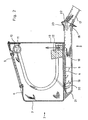
- the suction and protective hood 1 essentially consists of a hood part 2 and a suction mare 3 directed towards the open side, which is connected to the hood part 2 via an opening 4 in the working base 5 of the hood part.
- the hood part 2 is composed of an upper side 6 inclined on the body side, which merges into a vertical wall part 7 and a work floor 5.
- the side edges of the hood part have collar parts 8 which run around on both sides.
- the edge areas of the hood part 2 are rounded.
- the hood part 2 is preferably made of transparent, scratch-resistant hard plastic material, for. B. acrylic glass.
- the top of the hood part 2 has a rectangular recess into which a viewing window 9 is embedded.
- the lens 9 is connected via screw or clamp connections to the top of the hood part, so that it can be replaced if necessary.
- a disc 13 is pivotally attached via hinges, which covers the open side of the hood part, if necessary.
- the disc 13 is preferably made of the same transparent plastic material as the hood part 2.
- an L-profile strip 10 is attached with one leg. As FIG. 2 shows, it carries an illumination device 11.
- the working floor 5 of the hood part 2 has a beveled block 12 on the open side, on which a workpiece can be supported.
- the support block 12 is preferably made of wood.
- a holder for tools can be attached behind the support block 12. In this position, the tool does not hinder the insertion of a workpiece and it can be reached quickly at any time.
- the suction nozzle 3 preferably consists of a square hollow profile made of light metal. According to FIG. 2, it is composed of a front and a rear section 16, 17. A hinge 18 connects the two parts together. The rear section 17 is removable from the suction line z. B. a fan, which also serves as a bracket.
- the front section 16 of the suction nozzle 3 is connected to the working floor 5 of the hood part 2. It can have side plates (not shown) which support the working floor 5 of the hood part 2.
- the front section 16 is chamfered on the body side to avoid injuries.
- a lock ensures that the flap 19 is held in the open position. While closing the flap 20 can be operated a contact (not shown) that breaks the circuit of the fan. This prevents possible losses when working with precious metal.
- the hood part 2 can be tilted downwards from the horizontal.
- a bracket 22 between the two sections 16, 17, the inclination of the hood part 2 can be changed stepwise or continuously.
- locking disks are indicated, which allow the position of the hood part 2 to be adjusted in stages.
- brackets are known and those skilled in the art will select the most suitable design for use.
- the opening between the two sections of the suction nozzle 3 closes a bellows sleeve 23, which encompasses the ends of the sections 16, 17 in the area of the holder in a form-fitting manner.
- the bellows ensures the free mobility of the front section 16 with the hood part 2 without impairing the suction power of the suction nozzle.
Landscapes
- Health & Medical Sciences (AREA)
- Oral & Maxillofacial Surgery (AREA)
- Dentistry (AREA)
- Epidemiology (AREA)
- Life Sciences & Earth Sciences (AREA)
- Animal Behavior & Ethology (AREA)
- General Health & Medical Sciences (AREA)
- Public Health (AREA)
- Veterinary Medicine (AREA)
- Dental Tools And Instruments Or Auxiliary Dental Instruments (AREA)
- Prevention Of Fouling (AREA)
Priority Applications (1)
| Application Number | Priority Date | Filing Date | Title |
|---|---|---|---|
| AT83102750T ATE24678T1 (de) | 1982-04-30 | 1983-03-21 | Absaug- und schutzhaube besonders fuer ein zahntechnisches labor. |
Applications Claiming Priority (2)
| Application Number | Priority Date | Filing Date | Title |
|---|---|---|---|
| DE8212427U | 1982-04-30 | ||
| DE19828212427U DE8212427U1 (de) | 1982-04-30 | 1982-04-30 | Absaug- und schutzhaube fuer ein zahntechnisches labor |
Publications (3)
| Publication Number | Publication Date |
|---|---|
| EP0093257A2 true EP0093257A2 (fr) | 1983-11-09 |
| EP0093257A3 EP0093257A3 (en) | 1985-05-08 |
| EP0093257B1 EP0093257B1 (fr) | 1987-01-07 |
Family
ID=6739607
Family Applications (1)
| Application Number | Title | Priority Date | Filing Date |
|---|---|---|---|
| EP83102750A Expired EP0093257B1 (fr) | 1982-04-30 | 1983-03-21 | Hotte d'aspiration et de protection en particulier pour un laboratoire de dentiste |
Country Status (3)
| Country | Link |
|---|---|
| EP (1) | EP0093257B1 (fr) |
| AT (1) | ATE24678T1 (fr) |
| DE (2) | DE8212427U1 (fr) |
Cited By (7)
| Publication number | Priority date | Publication date | Assignee | Title |
|---|---|---|---|---|
| DE3543602A1 (de) * | 1984-12-28 | 1986-07-10 | Urawa Kohgyo Co., Ltd., Kuki, Saitama | Vorrichtung zur bearbeitung von gegenstaenden |
| EP0276638A3 (en) * | 1987-01-30 | 1989-02-01 | Officine Augusto Cattani & C. S.P.A. | A work rest, as used in particular by dental techniciansa work rest, as used in particular by dental technicians and goldsmiths and goldsmiths |
| DE9404740U1 (de) * | 1994-03-21 | 1994-06-30 | Zubler Gerätebau GmbH, 89231 Neu-Ulm | Reinigungssystem an einem Arbeitstisch, insbesondere für Zahntechniker |
| EP0930134A1 (fr) * | 1998-01-15 | 1999-07-21 | Kaltenbach & Voigt Gmbh & Co. | Table pour travail technique médical ou dentaire |
| FR2806619A1 (fr) | 2000-03-23 | 2001-09-28 | Alguerre Michel D | Systeme de protection pour laboratoire de protheses dentaires |
| AT412061B (de) * | 2002-09-26 | 2004-09-27 | Kotschy Peter Dr | Staub-, aerosol-auffang- und infektions-schutzeinrichtung für den zahnärztlichen gebrauch |
| WO2005005103A1 (fr) * | 2003-07-09 | 2005-01-20 | Somu Rangaswamy | Accessoire a utiliser pour un outil de meulage |
Families Citing this family (2)
| Publication number | Priority date | Publication date | Assignee | Title |
|---|---|---|---|---|
| DE3430224A1 (de) * | 1984-08-17 | 1986-02-27 | Bernhard 8702 Eisingen Hauser | Arbeitsplatzschutzvorrichtung zum durchfuehren manueller arbeiten |
| DE102006024100A1 (de) * | 2006-05-23 | 2007-11-29 | Richter, Heinz, Dipl.-Ing. | Staubabsaughaube (mobil) für handgeführte Maschinen |
Family Cites Families (3)
| Publication number | Priority date | Publication date | Assignee | Title |
|---|---|---|---|---|
| DE423479C (de) * | 1926-01-05 | Alma Niefind | Staubfaenger fuer zahnaerztliche Geraete | |
| US1374075A (en) * | 1919-04-18 | 1921-04-05 | David Stokely Etheridge | Receptacle and separator for particles of gold and other precious metals |
| DE527639C (de) * | 1930-05-03 | 1931-06-19 | Albert Oltersdorf | Staubfaenger fuer zahntechnische Arbeiten |
-
1982
- 1982-04-30 DE DE19828212427U patent/DE8212427U1/de not_active Expired
-
1983
- 1983-03-21 DE DE8383102750T patent/DE3368881D1/de not_active Expired
- 1983-03-21 EP EP83102750A patent/EP0093257B1/fr not_active Expired
- 1983-03-21 AT AT83102750T patent/ATE24678T1/de not_active IP Right Cessation
Cited By (8)
| Publication number | Priority date | Publication date | Assignee | Title |
|---|---|---|---|---|
| DE3543602A1 (de) * | 1984-12-28 | 1986-07-10 | Urawa Kohgyo Co., Ltd., Kuki, Saitama | Vorrichtung zur bearbeitung von gegenstaenden |
| EP0276638A3 (en) * | 1987-01-30 | 1989-02-01 | Officine Augusto Cattani & C. S.P.A. | A work rest, as used in particular by dental techniciansa work rest, as used in particular by dental technicians and goldsmiths and goldsmiths |
| DE9404740U1 (de) * | 1994-03-21 | 1994-06-30 | Zubler Gerätebau GmbH, 89231 Neu-Ulm | Reinigungssystem an einem Arbeitstisch, insbesondere für Zahntechniker |
| EP0930134A1 (fr) * | 1998-01-15 | 1999-07-21 | Kaltenbach & Voigt Gmbh & Co. | Table pour travail technique médical ou dentaire |
| FR2806619A1 (fr) | 2000-03-23 | 2001-09-28 | Alguerre Michel D | Systeme de protection pour laboratoire de protheses dentaires |
| EP1138273A1 (fr) | 2000-03-23 | 2001-10-04 | New Protect Systeme de Protection | Système de protection pour laboratoire de prothèses dentaires |
| AT412061B (de) * | 2002-09-26 | 2004-09-27 | Kotschy Peter Dr | Staub-, aerosol-auffang- und infektions-schutzeinrichtung für den zahnärztlichen gebrauch |
| WO2005005103A1 (fr) * | 2003-07-09 | 2005-01-20 | Somu Rangaswamy | Accessoire a utiliser pour un outil de meulage |
Also Published As
| Publication number | Publication date |
|---|---|
| EP0093257A3 (en) | 1985-05-08 |
| ATE24678T1 (de) | 1987-01-15 |
| DE3368881D1 (en) | 1987-02-12 |
| EP0093257B1 (fr) | 1987-01-07 |
| DE8212427U1 (de) | 1982-09-30 |
Similar Documents
| Publication | Publication Date | Title |
|---|---|---|
| EP0093257B1 (fr) | Hotte d'aspiration et de protection en particulier pour un laboratoire de dentiste | |
| EP0882525B1 (fr) | Etabli de laboratoire | |
| DE3104340C2 (de) | Tragbare Kreissäge | |
| EP3667179B1 (fr) | Dispositif de cuisine avec une hotte aspirante | |
| DE3017665A1 (de) | Bergbaumaschine | |
| DE60304775T2 (de) | Anordnung zum Schützen eines Anschlags für eine Gehrungssäge | |
| DE3341239A1 (de) | Absaughaube | |
| DE3615736A1 (de) | Kreissaege, insbesondere handkreissaege | |
| EP2145134A1 (fr) | Hotte aspirante | |
| DE19815587A1 (de) | Arbeitstisch, insbesondere für Dentallabors | |
| DE2736686C3 (de) | Einrichtung zur elektrochemischen Bearbeitung | |
| DE19918445B4 (de) | Arbeitstisch | |
| DE19506966C2 (de) | Absaugkasten | |
| AT399466B (de) | Obenliegende schutzvorrichtung mit staubabsaugung für kreissägen | |
| DE102013008019A1 (de) | Laborabzug mit neuartiger Arbeitsöffnung | |
| EP4410235B1 (fr) | Dispositif d'aspiration | |
| EP3459666A1 (fr) | Scie | |
| DE3106019C2 (de) | Schutzschild für Arbeiten bei Rauch- und/oder Gasentwicklung | |
| EP0192673B1 (fr) | Dispositif de protection d'un poste de travail pour l'execution d'operations manuelles | |
| DE4103122C2 (fr) | ||
| DE29612204U1 (de) | Grillstand | |
| DE2754186A1 (de) | Handkreissaege mit einer in der schutzhaube der saege angebrachten spanauswurfoeffnung | |
| DE3543602A1 (de) | Vorrichtung zur bearbeitung von gegenstaenden | |
| DE3114064C2 (de) | Vorrichtung zum Bearbeiten zahntechnischer Werkstücke | |
| DE3008752A1 (de) | Handgefuehrtes schweissschild |
Legal Events
| Date | Code | Title | Description |
|---|---|---|---|
| PUAI | Public reference made under article 153(3) epc to a published international application that has entered the european phase |
Free format text: ORIGINAL CODE: 0009012 |
|
| AK | Designated contracting states |
Designated state(s): AT BE CH DE FR GB IT LI NL SE |
|
| PUAL | Search report despatched |
Free format text: ORIGINAL CODE: 0009013 |
|
| AK | Designated contracting states |
Designated state(s): AT BE CH DE FR GB IT LI NL SE |
|
| 17P | Request for examination filed |
Effective date: 19851010 |
|
| 17Q | First examination report despatched |
Effective date: 19860505 |
|
| GRAA | (expected) grant |
Free format text: ORIGINAL CODE: 0009210 |
|
| AK | Designated contracting states |
Kind code of ref document: B1 Designated state(s): AT BE CH DE FR GB IT LI NL SE |
|
| REF | Corresponds to: |
Ref document number: 24678 Country of ref document: AT Date of ref document: 19870115 Kind code of ref document: T |
|
| REF | Corresponds to: |
Ref document number: 3368881 Country of ref document: DE Date of ref document: 19870212 |
|
| PGFP | Annual fee paid to national office [announced via postgrant information from national office to epo] |
Ref country code: AT Payment date: 19870330 Year of fee payment: 5 |
|
| PGFP | Annual fee paid to national office [announced via postgrant information from national office to epo] |
Ref country code: NL Payment date: 19870331 Year of fee payment: 5 |
|
| ITF | It: translation for a ep patent filed | ||
| PLBE | No opposition filed within time limit |
Free format text: ORIGINAL CODE: 0009261 |
|
| STAA | Information on the status of an ep patent application or granted ep patent |
Free format text: STATUS: NO OPPOSITION FILED WITHIN TIME LIMIT |
|
| 26N | No opposition filed | ||
| PG25 | Lapsed in a contracting state [announced via postgrant information from national office to epo] |
Ref country code: AT Effective date: 19880321 |
|
| PG25 | Lapsed in a contracting state [announced via postgrant information from national office to epo] |
Ref country code: SE Effective date: 19880322 |
|
| PG25 | Lapsed in a contracting state [announced via postgrant information from national office to epo] |
Ref country code: LI Effective date: 19880331 Ref country code: CH Effective date: 19880331 |
|
| BERE | Be: lapsed |
Owner name: LOBEMEIER HORST Effective date: 19880331 |
|
| PG25 | Lapsed in a contracting state [announced via postgrant information from national office to epo] |
Ref country code: NL Effective date: 19881001 |
|
| NLV4 | Nl: lapsed or anulled due to non-payment of the annual fee | ||
| PG25 | Lapsed in a contracting state [announced via postgrant information from national office to epo] |
Ref country code: GB Free format text: LAPSE BECAUSE OF NON-PAYMENT OF DUE FEES Effective date: 19881122 |
|
| GBPC | Gb: european patent ceased through non-payment of renewal fee | ||
| PG25 | Lapsed in a contracting state [announced via postgrant information from national office to epo] |
Ref country code: FR Free format text: LAPSE BECAUSE OF NON-PAYMENT OF DUE FEES Effective date: 19881130 |
|
| REG | Reference to a national code |
Ref country code: CH Ref legal event code: PL |
|
| REG | Reference to a national code |
Ref country code: FR Ref legal event code: ST |
|
| PG25 | Lapsed in a contracting state [announced via postgrant information from national office to epo] |
Ref country code: BE Effective date: 19890331 |
|
| PG25 | Lapsed in a contracting state [announced via postgrant information from national office to epo] |
Ref country code: DE Effective date: 19891201 |
|
| EUG | Se: european patent has lapsed |
Ref document number: 83102750.3 Effective date: 19881206 |