EP0093615A1 - Machines rotatives électriques à vitesse variable - Google Patents
Machines rotatives électriques à vitesse variable Download PDFInfo
- Publication number
- EP0093615A1 EP0093615A1 EP83302486A EP83302486A EP0093615A1 EP 0093615 A1 EP0093615 A1 EP 0093615A1 EP 83302486 A EP83302486 A EP 83302486A EP 83302486 A EP83302486 A EP 83302486A EP 0093615 A1 EP0093615 A1 EP 0093615A1
- Authority
- EP
- European Patent Office
- Prior art keywords
- auxiliary
- main
- rotor
- inverter
- machine
- Prior art date
- Legal status (The legal status is an assumption and is not a legal conclusion. Google has not performed a legal analysis and makes no representation as to the accuracy of the status listed.)
- Granted
Links
- 230000006698 induction Effects 0.000 claims abstract description 43
- 238000000034 method Methods 0.000 claims description 6
- 230000001419 dependent effect Effects 0.000 claims 1
- 241000246142 Chamaecytisus Species 0.000 abstract description 19
- 238000010276 construction Methods 0.000 description 4
- 230000008878 coupling Effects 0.000 description 4
- 238000010168 coupling process Methods 0.000 description 4
- 238000005859 coupling reaction Methods 0.000 description 4
- 238000010586 diagram Methods 0.000 description 4
- 230000000694 effects Effects 0.000 description 2
- 230000000712 assembly Effects 0.000 description 1
- 238000000429 assembly Methods 0.000 description 1
- 238000012986 modification Methods 0.000 description 1
- 230000004048 modification Effects 0.000 description 1
- 238000012544 monitoring process Methods 0.000 description 1
- 230000001172 regenerating effect Effects 0.000 description 1
- 239000007787 solid Substances 0.000 description 1
- 230000003068 static effect Effects 0.000 description 1
Images


Classifications
-
- H—ELECTRICITY
- H02—GENERATION; CONVERSION OR DISTRIBUTION OF ELECTRIC POWER
- H02K—DYNAMO-ELECTRIC MACHINES
- H02K17/00—Asynchronous induction motors; Asynchronous induction generators
- H02K17/02—Asynchronous induction motors
- H02K17/34—Cascade arrangement of an asynchronous motor with another dynamo-electric motor or converter
- H02K17/36—Cascade arrangement of an asynchronous motor with another dynamo-electric motor or converter with another asynchronous induction motor
-
- H—ELECTRICITY
- H02—GENERATION; CONVERSION OR DISTRIBUTION OF ELECTRIC POWER
- H02P—CONTROL OR REGULATION OF ELECTRIC MOTORS, ELECTRIC GENERATORS OR DYNAMO-ELECTRIC CONVERTERS; CONTROLLING TRANSFORMERS, REACTORS OR CHOKE COILS
- H02P5/00—Arrangements specially adapted for regulating or controlling the speed or torque of two or more electric motors
- H02P5/74—Arrangements specially adapted for regulating or controlling the speed or torque of two or more electric motors controlling two or more AC dynamo-electric motors
Definitions
- This invention relates generally to variable speed rotating dynamoelectric machinery and in particular to variable speed induction motors and motor drive systems.
- an induction motor drive system of this particular type is provided in a co-pending European Patent Application No. 82306672.5 entitled "Electrical Machine” filed December 14th, 1982 in the name of The Garrett Corporation, and not yet published. That application describes an induction motor drive system including a main machine and a smaLLer auxiliary machine, installed in a common housing. The rotors of the two machines are mounted on a common shaft, and both rotors have a squirrel-cage construction. The rotor bars of the main machine and of the auxiliary machine are concatenated at their adjoining ends and are connected to conventional end rings at their extremities.
- the main machine is supplied from a Line-commutated inverter, and the auxiliary machine is supplied from a separate, forced-commutated inverter.
- the two inverters are supplied by separate variable d.c. Link voltage sources, such as controlled rectifiers or chopper- . type input inverters.
- A.C. induction motors typically operate at a Lagging power factor , and are therefore inherently incompatible with Line-commutated inverters, which function properly only if they supply a Leading power factor Load.
- a static inverter that is capable of supplying lagging power factor loads must have auxiliary circuitry to force the commutation of its solid state switching devices. This auxiliary circuitry makes such a forced-commutated inverter significantly more expensive than a Line-commutated inverter of comparable power rating.
- the forced-commutated inverter for the auxiliary machine is specially configured such, that the stator of the main machine appears to have a Leading power factor.
- the frequency and voltage levels of the A.C. signals supplied by the forced-commutated inverter to the auxiliary stator are coupled through the respective auxiliary and main rotors to the main stator, causing its current to Lead its voltage. This permits the use of a Line-commutated inverter to drive the main machine, thereby providing a significant cost savings for a machine of a given size.
- the induction motor drive system described in the aforementioned co-pending application produces a high starting torque and is suitable for use in applications requiring power ratings of up to several hundred horsepower.
- ALso its use of a Line-commutated inverter in place of a forced-commutated inverter provides a significant cost savings over known prior systems.
- the present invention can fulfill this need.
- the present invention is embodied in a variable speed induction machine that includes an induction motor operating at a Leading power factor.
- the machine includes means for providing reactive power to the induction motor's rotor, to permit Line commutation of an inverter supplying the motor's stator, and to permit the inverter to be supplied by a substantially constant, d.c. Link voltage.
- the invention may thereby provide substantial cost savings over other variable speed systems of this type, which achieve Line commutation of their inverters only by using a d.c. Link voltage that is variable.
- a variable speed dynamoelectric induction machine comprises a stator and a rotor, referred to as the first mentioned rotor, and co-operating electromagnetically with the stator, an inverter connected to the stator, and supply means connected to the inverter for supplying a substantially constant d.c. voltage thereto, and means for providing reactive power to the first-mentioned rotor to permit Line commutation of the inverter.
- the variable speed induction machine may include a main machine and a smaller auxiliary machine, installed in a common housing.
- the rotors of the two machines are mounted on a common shaft and both may have a squirrel-cage construction.
- the rotor bars of the main machine and of the auxiliary machine are concatenated at their adjoining ends and are connected to conventional end rings at their extremities.
- the Line commutated inverter supplied the main machine's stator, and a separate forced-commutated inverter supplies the auxiliary machine's stator.
- a diode rectifier, supplied by an a.c. Line through a set of switches may be used to supply the substantially constant d.c. Link voltage to the Line-commutated inverter.
- a controller adjusts the forced-commutated inverter to supply an a.c. signal hawing a selectable frequency and voltage level, such that a prescribed reactive power is coupled through the respective auxiliary and main rotors to the main stator. This causes the main stator to appear to constitute a Leading power factor Load, and permits the use of a Line-commutated inverter supplied from a substantially constant d.c. Link voltage.
- the switches coupling the a.c. Line to the diode rectifier are opened and the switching elements, e.g. thyristors in the Line-commutated inverter are gated on continuously. This effectively shorts the main motor circuit through the Line-commutated inverter--d.c.Link- diode rectifier path, and the motor then operates Like a conventional squirrel-cage induction machine fed through the forced-commutated inverter. Since,.
- the fcrced-commutated inverter need not have a capacity that is particularly Large in comparison to that of the Line-commutated inverter.
- the switches coupling the a.c. voltage source to the diode rectifier are closed.and the constant d.c. Link voltage is thereafter supplied tothe Line-commutated inverter.
- the controller then controllably varies the specific frequency and voltage LeveL of the a.c. signal supplied by the forced-commutated inverter to the auxiliary stator, such that the motor drive system operates at a selected speed.
- the motor drive system may include a plurality of machines, each having a main machine with a main stator and a main rotor and an auxiliary machine with an auxiliary stator and an auxiliary rotor.
- a separate forced-commutated inverter supplies current to each auxiliary stator, and a single Line-commutated inverter, supplied by a substantially constant d.c. Link voltage, drives all of the main stators in parallel.
- the present invention may comprise a variable speed induction motor drive system including a machine housing; a main machine mounted within the machine housing and including a main stator and a main rotor; a main inverter connected to the main stator for supplying electric current thereto, supply means connected to the main inverter for supplying a substantially constant d.c.
- an auxiliary machine mounted within the machine housing, the auxiliary machine including an auxiliary stator and an auxiliary rotor, the auxiliary rotor being electrically connected to the main rotor to permit electric current to flow therebetween;and an auxiliary inverter connected to the auxiliary stator for supplying electric current thereto whereby an electric current is induced in the auxiliary rotor , said induced current flowing from the auxiliary rotor to the main rotor to produce a voltage for Line-commutating the main inverter.
- the present invention resides in a method for driving a variable speed dynamoelectric induction machine having a squirrel-cage rotor and a stator co-operating electromagnetically with the rotor , the method being characterised by the steps of supplying a substantially constant d.c. voltage to an inverter connected to the stator, and delivering reactive power to the squirrel-cage rotor to permit Line commutation of the inverter.
- FIGURE 5 is an exploded perspective view of the motor, showing it to include a main machine 15 and an auxiliary machine 17, installed in a common. housing 19.
- the main machine includes a three-phase main stator assembly 21, and a main rotor assembly 23, preferably of a squirrel-cage construction, and the auxiliary machine Likewise includes a three-phase auxiliary stator assembly 25 and an auxiliary rotor assembly 27 also preferably of a squirrel-cage construction.
- the rotor bars of the main and auxiliary rotor assemblies 23 and 27 are electrically concatenated at their adjoining ends as illustrated in FIGURE 5, and are connected to conventional end rings at their other ends, as described in the aforesaid AppLication No. 82306672.5.
- the main rotor assembly and the auxiliary rotor asembly are mounted on a common rotor shaft 29, which is rotatably mounted within the housing by ends bells 31 and 33.
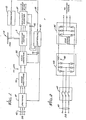
- a main inverter 35 supplies three-phase eLectricaL power to the main stator assembly, 21, and an auxiliary inverter 37 supplies three-phase electrical power to the auxiliary stator assembly 25,.
- the two inverters which are Located within an inverter housing 39 (FIGURE 5) both include a plurality of thyristors that are gated on at appropriate times, to commutate the d.c. Link voltages supplied to them.
- a controller 40 couples appropriate gating signals over Lines 41 and 42 to the main and auxiliary inverters, respectively, to controLLabLy adjust the frequencies and voltage LeveLs of the a.c. signals they supply. This effects the prescribed motor speed control.
- An induction motor such as the main machine 15 inherently operates at a Lagging power factor, and is therefore ordinarily incompatible with a Line-commutated inverter, which can drive only Leading power factor Loads.
- the main machine can be made to be compatible with a Line-commutated inverter by coupling the appropriate reactive power to it via the auxiliary machine 17.
- a variable speed is achieved by controllably varying the frequencies ardthe voltage LeveLs of the a.c. signals suppLied by the main inverter and the auxiliary inverter.
- This ordinarily requires the use of two separate phase-delay rectifiers for supplying d.c. Link voltages that are variable, thereby adding to the system's complexity and cost. This added complexity and cost is believed to be unnecessary in situations not requiring a high starting torque, such as in an induction motor drive system for driving fan-type Load.
- the controller 40 controllably adjusts the frequency and voltage of the a.c. signal supplied by the auxiliary inverter 37 and controllably adjusts the frequency of the a.c. signal supplied main inverter 35, such that the main inverter can be Line-commutated and supplied by a d.c. Link having a substantially constant voltage.
- the drive system of the invention provides a starting torque somewhat reduced from that which can be achieved using variable d.c. Link voltage, the system is suitable for use in driving many Loads, such as fan-type loads.
- the constant d.c. Link voltage supplied to the main inverter 35 is produced by a diode rectifier 43, which in turn is supplied from a three phase power Line 45 via a set of electrical switches 47.
- the diode rectifier includes an inductor 49 following its diodes, to reduce the ripple in the rectified voltage signal.
- FIGURES 3 and 4 depict the prescribed relationships between the voltages and frequencies of the respective main and auxiliary inverters 35 and 37, as a function of motor speed.
- FIGURE 3 in particular depicts the relationship between main inverter frequency and auxiliary inverter voltage, for a set of fixed motor speeds ranging from 50 percent to 100 percent. of maximum speed.
- the auxiliary inverter voltage is expressed as a percentage of the main inverter voltage.
- Boundaries for the auxiliary inverter voltage of plus and minus 12.5 percent of the main inverter's voltage are included in the figure, to indicate arbitrary Limits imposed to Limit the auxiliary inverter's rating.
- the Locus of both the main inverter's frequency and the auxiliary inverter's voltage is indicated by a heavy solid Line 50 for a 2:1 speed range.
- FIGURE 4 depicts the prescribed values for the frequency of the main inverter 35 and for the frequency and voltage of the auxiliary inverter 37,for motor speeds ranging from zero to 100 percent of maximum speed.
- the curves for the main inverters frequency and the auxiliary inverters voltage, for motor speeds of 50 to ⁇ 100 percent are derived from the Locus 50 in FIGURE 3.
- the controLLer 40 controllably adjusts the frequency of the main inverter 35 and the frequency and voltage LeveL of the auxiliary inverter 37 to correspond to the values indicated by the graph of FIGURE 4. For example, if a speed equal to about 60 percent of the drive system's maximum speed is desired, the controller controllably adjusts the main inverter's frequency to be about 84Hz, the auxiliary inverters frequency to be about negative 15Hz and the auxiliary inverters voltage to be about 12.5 percent that of the main inverter. In this context, a negative frequency simply means that the three phases are switched in a sequence ACB rather ABC.
- the controller 40 opens the set of switches 47, as shown in FIGURE 2, and gates on continuously the thyristors in the main inverter 35. This in effect shorts the main machine 15 via the main inverter and the diode rectifier 43.
- the auxiliary inverter 37 supplies power to the auxiliary machine 17, which operates Like a conventional squirrel-cage induction motor. Since in the case of fan-type Loads the power requirement, even at half-speed, is ordinarily Less than about 15 percent of its maximum rating, the auxiliary inverter has sufficient capacity to accelerate the motor to this speed.
- the controller closes the switches and controLLabLy adjusts the main inverter and the auxiliary inverter, as indicated by the graph of FIGURE 4 discussed above.
- the controller 40 again opens the set of switches 47, shorting the main machine 15 and thereby preventing the drive system from regenerating through the main inverter 35.
- the auxiliary inverter 37 handles all of the power up to its capacity.
- the motor drive system further includes a tachometer 51 for monitoring the speed of the motor-driven fan 13 and coupling a signal representative of that speed over Line 53 to the controller 40. This permits the controller to achieve a more accurate control of the motor speed.
- FIGURE 6 depicts an alternative embodiment of the invention, which includes a plurality of separate motor drive systems. Each system is similar to the motor drive system described above with references to FIGURES 1-5.
- a first motor drive sytem includes a main machine having a three phase man stator 53a and a corresponding main rotor 55a, and an auxiliary machine having a three phase auxiliary stator 57a and a corresponding auxilia.ry rotor 59a which is electrically concatenated with the main rotor 55a.
- a main inverter 61 supplies three phase power over a power Line 63 to the main stator, and an auxiliary inverter 65a provides three phase power to the auxiliary stator.
- a controller 67a connected between the main rotor and the auxiliary.
- inverter regulates the frequency and voltage LeveL of thea.c. signal supplied by the auxiliary inverter, such that a prescribed reactive power is coupled through the respective rotors to the main stator.
- the d.c. Link voltage is supplied to the main inverter by a diode rectifier 69, which in turn is connected to a three-phase power Line 71 through a set of electrical switches 73.
- a second system includes a main machine having a main stator 53b and a main rotor 55b, and an auxiliary machine having an auxiliary stator 57b, and an auxiliary rotor 59b.
- the main stator is supplied with three-phase power over the power Line 63 from the main inverter 61.
- a plurality of additional machines can Likewise be connected to the main inverter 61 in the manner described above.
- the invention makes it possible to control the speed of the respective rotors without altering the main inverter frequency, by changing the frequency and voltage LeveL of each auxiliary inverters a.c. output to achieve a desired slip.
- the present invention provides an improved induction motor drive system that can operate over a wide speed range.
- a prescribed reactive power is coupled to the motors rotor, to permit Line commutation of an inverter supplying the motors stator, and to permit the inverter to be supplied by a substantially constant d.c. Link voltage.
Landscapes
- Engineering & Computer Science (AREA)
- Power Engineering (AREA)
- Control Of Ac Motors In General (AREA)
Applications Claiming Priority (2)
| Application Number | Priority Date | Filing Date | Title |
|---|---|---|---|
| US06/374,375 US4476424A (en) | 1982-05-03 | 1982-05-03 | Variable speed induction motor drive system |
| US374375 | 1982-05-03 |
Publications (2)
| Publication Number | Publication Date |
|---|---|
| EP0093615A1 true EP0093615A1 (fr) | 1983-11-09 |
| EP0093615B1 EP0093615B1 (fr) | 1988-10-26 |
Family
ID=23476539
Family Applications (1)
| Application Number | Title | Priority Date | Filing Date |
|---|---|---|---|
| EP83302486A Expired EP0093615B1 (fr) | 1982-05-03 | 1983-05-03 | Machines rotatives électriques à vitesse variable |
Country Status (5)
| Country | Link |
|---|---|
| US (1) | US4476424A (fr) |
| EP (1) | EP0093615B1 (fr) |
| JP (1) | JPS58204795A (fr) |
| CA (1) | CA1205129A (fr) |
| DE (1) | DE3378343D1 (fr) |
Cited By (10)
| Publication number | Priority date | Publication date | Assignee | Title |
|---|---|---|---|---|
| EP0183687A4 (fr) * | 1982-05-20 | 1987-09-07 | Frederick W Klatt | Appareil electrique rotatif. |
| EP0577980A1 (fr) * | 1992-06-10 | 1994-01-12 | Fuji Electric Co., Ltd. | Mécanisme d'entraînement à vitesse variable pour courant alternatif et véhicule électrique utilisant celui-ci |
| CN101442240B (zh) * | 2007-11-22 | 2011-11-09 | 王光顺 | 一种可调电压永磁发电机 |
| US8320224B2 (en) | 2003-02-20 | 2012-11-27 | Koninklijke Philips Electronics N.V. | Information carrier comprising access information and dummy information |
| US8916984B2 (en) | 2011-09-15 | 2014-12-23 | Siemens Aktiengesellschaft | Wind turbine |
| CN110635650A (zh) * | 2019-10-23 | 2019-12-31 | 六安正辉优产机电科技有限公司 | 三定子无刷永磁电机 |
| CN110635647A (zh) * | 2019-10-23 | 2019-12-31 | 六安正辉优产机电科技有限公司 | 一种永磁无刷电机的变矩调速方法 |
| CN110635651A (zh) * | 2019-10-23 | 2019-12-31 | 六安正辉优产机电科技有限公司 | 一种利用磁通调速的永磁无刷电机 |
| CN110635649A (zh) * | 2019-10-23 | 2019-12-31 | 六安正辉优产机电科技有限公司 | 一种永磁无刷电机的调速构件 |
| WO2021145864A1 (fr) | 2020-01-14 | 2021-07-22 | Adventech, Llc | Conceptions améliorées de moteur à induction à enroulement inversé, systèmes et procédés |
Families Citing this family (16)
| Publication number | Priority date | Publication date | Assignee | Title |
|---|---|---|---|---|
| US4600874A (en) * | 1985-01-26 | 1986-07-15 | General Electric Company | Excitation current control for induction motor drive using load commutated inverter circuit |
| US4723202A (en) * | 1987-04-02 | 1988-02-02 | The Garrett Corporation | Converter-fed AC machine without damper winding |
| US4994684A (en) * | 1989-01-30 | 1991-02-19 | The State Of Oregon Acting By And Through The State Board Of Higher Education On Behalf Of Oregon State University | Doubly fed generator variable speed generation control system |
| US5239251A (en) * | 1989-06-30 | 1993-08-24 | The State Of Oregon Acting By And Through The State Board Of Higher Education On Behalf Of Oregon State University | Brushless doubly-fed motor control system |
| US5028804A (en) * | 1989-06-30 | 1991-07-02 | The State Of Oregon Acting By And Through The State Board Of Higher Education On Behalf Of Oregon State University | Brushless doubly-fed generator control system |
| US5083077A (en) * | 1990-07-31 | 1992-01-21 | The State Of Oregon Acting By And Through The State Board Of Higher Education On Behalf Of Oregon State University | Brushless doubly-fed generation system for vehicles |
| US5243268A (en) * | 1991-07-17 | 1993-09-07 | Klatt Frederick W | Electric machine system |
| FR2698386B1 (fr) * | 1992-11-23 | 1995-01-06 | Asselin | Aiguilleteuse et procédé d'aiguilletage s'y rapportant. |
| US5636420A (en) * | 1992-11-23 | 1997-06-10 | Asselin | Needling machine and needling method related thereto |
| US6048269A (en) * | 1993-01-22 | 2000-04-11 | Mgm Grand, Inc. | Coinless slot machine system and method |
| US7161257B2 (en) * | 2004-03-08 | 2007-01-09 | Ingersoll-Rand Energy Systems, Inc. | Active anti-islanding system and method |
| US8305025B2 (en) * | 2008-10-07 | 2012-11-06 | Siemens Industry, Inc. | Methods and apparatus for controlling multiple A.C. induction machines from a single inverter |
| US9467081B2 (en) * | 2014-09-29 | 2016-10-11 | Ingeteam Power Technology, S.A. | Protection system for a power converter connected to a doubly fed induction generator |
| JP6344529B2 (ja) * | 2015-06-22 | 2018-06-20 | 日産自動車株式会社 | 車両用補機駆動装置 |
| US10801766B2 (en) | 2019-01-30 | 2020-10-13 | Regal Beloit America, Inc. | Drive circuit for a variable speed fan motor |
| US11959679B2 (en) | 2019-01-30 | 2024-04-16 | Regal Beloit America, Inc. | Drive circuit for a variable speed fan motor |
Citations (6)
| Publication number | Priority date | Publication date | Assignee | Title |
|---|---|---|---|---|
| AT46682B (de) * | 1910-01-24 | 1911-02-25 | Anton Lang | Einrichtung zur Änderung der Tourenzahl einer Welle unter Benützung zweier Motoren in Kaskadenschaltung. |
| US3539891A (en) * | 1968-01-29 | 1970-11-10 | Villamos Ipari Kutato Intezet | Double-fed polyphase cascade machines and a method of producing such machines |
| GB1270247A (en) * | 1968-06-19 | 1972-04-12 | Dowty Rotol Ltd | Synchro-control systems |
| AT338384B (de) * | 1975-10-14 | 1977-08-25 | Elin Union Ag | Induktionsmaschinenkaskade |
| GB2043359A (en) * | 1979-02-15 | 1980-10-01 | Bendix Corp | Alternating current machine arrangement |
| EP0037307A1 (fr) * | 1980-03-24 | 1981-10-07 | Janusz Sobiepanek | Système de régulation de vitesse pour moteur asynchrone à double stator |
Family Cites Families (4)
| Publication number | Priority date | Publication date | Assignee | Title |
|---|---|---|---|---|
| JPS492928B1 (fr) * | 1969-11-25 | 1974-01-23 | ||
| US3753069A (en) * | 1971-11-18 | 1973-08-14 | Borg Warner | Start-up system for inverter driven motor including inverter bypass circuitry |
| JPS5837799B2 (ja) * | 1976-09-29 | 1983-08-18 | 三菱電機株式会社 | 電動機装置 |
| US4445081A (en) * | 1981-12-15 | 1984-04-24 | The Garrett Corporation | Leading power factor induction motor device |
-
1982
- 1982-05-03 US US06/374,375 patent/US4476424A/en not_active Expired - Lifetime
-
1983
- 1983-04-05 CA CA000425249A patent/CA1205129A/fr not_active Expired
- 1983-05-02 JP JP58076366A patent/JPS58204795A/ja active Pending
- 1983-05-03 DE DE8383302486T patent/DE3378343D1/de not_active Expired
- 1983-05-03 EP EP83302486A patent/EP0093615B1/fr not_active Expired
Patent Citations (6)
| Publication number | Priority date | Publication date | Assignee | Title |
|---|---|---|---|---|
| AT46682B (de) * | 1910-01-24 | 1911-02-25 | Anton Lang | Einrichtung zur Änderung der Tourenzahl einer Welle unter Benützung zweier Motoren in Kaskadenschaltung. |
| US3539891A (en) * | 1968-01-29 | 1970-11-10 | Villamos Ipari Kutato Intezet | Double-fed polyphase cascade machines and a method of producing such machines |
| GB1270247A (en) * | 1968-06-19 | 1972-04-12 | Dowty Rotol Ltd | Synchro-control systems |
| AT338384B (de) * | 1975-10-14 | 1977-08-25 | Elin Union Ag | Induktionsmaschinenkaskade |
| GB2043359A (en) * | 1979-02-15 | 1980-10-01 | Bendix Corp | Alternating current machine arrangement |
| EP0037307A1 (fr) * | 1980-03-24 | 1981-10-07 | Janusz Sobiepanek | Système de régulation de vitesse pour moteur asynchrone à double stator |
Cited By (17)
| Publication number | Priority date | Publication date | Assignee | Title |
|---|---|---|---|---|
| EP0183687A4 (fr) * | 1982-05-20 | 1987-09-07 | Frederick W Klatt | Appareil electrique rotatif. |
| EP0577980A1 (fr) * | 1992-06-10 | 1994-01-12 | Fuji Electric Co., Ltd. | Mécanisme d'entraînement à vitesse variable pour courant alternatif et véhicule électrique utilisant celui-ci |
| US5365153A (en) * | 1992-06-10 | 1994-11-15 | Fuji Electric Co., Ltd. | AC variable speed driving apparatus and electric vehicle using the same |
| US9720622B2 (en) | 2003-02-20 | 2017-08-01 | Koninklijke Philips N.V. | Information carrier comprising access information |
| US8320224B2 (en) | 2003-02-20 | 2012-11-27 | Koninklijke Philips Electronics N.V. | Information carrier comprising access information and dummy information |
| US8351313B2 (en) | 2003-02-20 | 2013-01-08 | Koninklijke Philips Electronics N.V. | Information carrier comprising access information |
| US8644118B2 (en) | 2003-02-20 | 2014-02-04 | Koninklijke Philips N.V. | Information carrier comprising access information |
| CN101442240B (zh) * | 2007-11-22 | 2011-11-09 | 王光顺 | 一种可调电压永磁发电机 |
| US8916984B2 (en) | 2011-09-15 | 2014-12-23 | Siemens Aktiengesellschaft | Wind turbine |
| CN110635647A (zh) * | 2019-10-23 | 2019-12-31 | 六安正辉优产机电科技有限公司 | 一种永磁无刷电机的变矩调速方法 |
| CN110635650A (zh) * | 2019-10-23 | 2019-12-31 | 六安正辉优产机电科技有限公司 | 三定子无刷永磁电机 |
| CN110635651A (zh) * | 2019-10-23 | 2019-12-31 | 六安正辉优产机电科技有限公司 | 一种利用磁通调速的永磁无刷电机 |
| CN110635649A (zh) * | 2019-10-23 | 2019-12-31 | 六安正辉优产机电科技有限公司 | 一种永磁无刷电机的调速构件 |
| WO2021145864A1 (fr) | 2020-01-14 | 2021-07-22 | Adventech, Llc | Conceptions améliorées de moteur à induction à enroulement inversé, systèmes et procédés |
| EP4088372A4 (fr) * | 2020-01-14 | 2023-01-25 | Adventech, LLC | Conceptions améliorées de moteur à induction à enroulement inversé, systèmes et procédés |
| US11979102B2 (en) | 2020-01-14 | 2024-05-07 | Adventech, Llc | Systems for networks of efficiently powered enhanced reverse-winding induction motor |
| EP4636974A3 (fr) * | 2020-01-14 | 2026-04-08 | Adventech, LLC | Conceptions de moteur à induction à enroulement inverse amélioré, systèmes et procédés |
Also Published As
| Publication number | Publication date |
|---|---|
| EP0093615B1 (fr) | 1988-10-26 |
| CA1205129A (fr) | 1986-05-27 |
| DE3378343D1 (en) | 1988-12-01 |
| JPS58204795A (ja) | 1983-11-29 |
| US4476424A (en) | 1984-10-09 |
Similar Documents
| Publication | Publication Date | Title |
|---|---|---|
| EP0093615A1 (fr) | Machines rotatives électriques à vitesse variable | |
| US5029263A (en) | Electric start control of a VSCF system | |
| US4550267A (en) | Redundant multiple channel electric motors and generators | |
| US4830412A (en) | Starting system and method using a hybrid permanent magnet/induction machine | |
| EP0467517B1 (fr) | Moteur à induction synchrone à double stator | |
| US7327048B2 (en) | Hybrid gas turbine engine starter-generator | |
| US4684873A (en) | Hybrid generating system | |
| US20020043954A1 (en) | Permanent magnet brushless electric motor system and method of using same | |
| JPS62210873A (ja) | 始動/発電装置 | |
| US4447737A (en) | Variable frequency induction generator | |
| US4311951A (en) | Apparatus and method for high slip operation of an AC electric motor at substantially zero rotation and substantially zero torque | |
| US6815920B2 (en) | Motor driver and system with phase-spaced redundancy | |
| EP0529873B1 (fr) | Moteur synchrone à induction sans balai avec deux stators | |
| EP0868771B1 (fr) | Systemes a moteur a reluctance variable | |
| US3378756A (en) | Variable speed constant frequency generating system | |
| US7034500B2 (en) | Electric drive assembly | |
| CA2382352C (fr) | Court-circuitage electronique d'enroulements de rotor | |
| US4030006A (en) | Speed controllable drive for an asynchronous motor | |
| US4024455A (en) | Rotary inverters for converting D.C. to A.C. | |
| JPS5917632B2 (ja) | ゼロ回転及びゼロ・トルク検出方法および装置 | |
| EP1267473B1 (fr) | Moteur d'induction a courant alternative et méthode pour son démarrage | |
| US3378757A (en) | Narrow frequency range, wide speed range, brushless a.c. generator | |
| CA1199673A (fr) | Excitateur sans balai pour utilisation avec un moteur synchrone a vitesse variable | |
| EP0442848B1 (fr) | Moteur à courant alternatif et vitesse variable utilisant un moteur à induction avec un rotor de court circuit | |
| US3339131A (en) | Multi-speed, self-excited ac motor system |
Legal Events
| Date | Code | Title | Description |
|---|---|---|---|
| PUAI | Public reference made under article 153(3) epc to a published international application that has entered the european phase |
Free format text: ORIGINAL CODE: 0009012 |
|
| AK | Designated contracting states |
Designated state(s): CH DE FR GB IT LI NL SE |
|
| 17P | Request for examination filed |
Effective date: 19840509 |
|
| ITF | It: translation for a ep patent filed | ||
| GRAA | (expected) grant |
Free format text: ORIGINAL CODE: 0009210 |
|
| AK | Designated contracting states |
Kind code of ref document: B1 Designated state(s): CH DE FR GB IT LI NL SE |
|
| PG25 | Lapsed in a contracting state [announced via postgrant information from national office to epo] |
Ref country code: NL Effective date: 19881026 Ref country code: FR Free format text: THE PATENT HAS BEEN ANNULLED BY A DECISION OF A NATIONAL AUTHORITY Effective date: 19881026 |
|
| REF | Corresponds to: |
Ref document number: 3378343 Country of ref document: DE Date of ref document: 19881201 |
|
| NLV1 | Nl: lapsed or annulled due to failure to fulfill the requirements of art. 29p and 29m of the patents act | ||
| EN | Fr: translation not filed | ||
| PG25 | Lapsed in a contracting state [announced via postgrant information from national office to epo] |
Ref country code: GB Effective date: 19890503 |
|
| PG25 | Lapsed in a contracting state [announced via postgrant information from national office to epo] |
Ref country code: SE Effective date: 19890504 |
|
| PG25 | Lapsed in a contracting state [announced via postgrant information from national office to epo] |
Ref country code: LI Effective date: 19890531 Ref country code: CH Effective date: 19890531 |
|
| PLBE | No opposition filed within time limit |
Free format text: ORIGINAL CODE: 0009261 |
|
| STAA | Information on the status of an ep patent application or granted ep patent |
Free format text: STATUS: NO OPPOSITION FILED WITHIN TIME LIMIT |
|
| 26N | No opposition filed | ||
| GBPC | Gb: european patent ceased through non-payment of renewal fee | ||
| REG | Reference to a national code |
Ref country code: CH Ref legal event code: PL |
|
| PG25 | Lapsed in a contracting state [announced via postgrant information from national office to epo] |
Ref country code: DE Effective date: 19900703 |
|
| EUG | Se: european patent has lapsed |
Ref document number: 83302486.2 Effective date: 19900412 |