EP0093630A1 - Chemise de protection contre les contaminations internes pour pistolet gynécologique, notamment pour bovins - Google Patents
Chemise de protection contre les contaminations internes pour pistolet gynécologique, notamment pour bovins Download PDFInfo
- Publication number
- EP0093630A1 EP0093630A1 EP83400691A EP83400691A EP0093630A1 EP 0093630 A1 EP0093630 A1 EP 0093630A1 EP 83400691 A EP83400691 A EP 83400691A EP 83400691 A EP83400691 A EP 83400691A EP 0093630 A1 EP0093630 A1 EP 0093630A1
- Authority
- EP
- European Patent Office
- Prior art keywords
- protective jacket
- jacket according
- gun
- shirts
- cylindrical element
- Prior art date
- Legal status (The legal status is an assumption and is not a legal conclusion. Google has not performed a legal analysis and makes no representation as to the accuracy of the status listed.)
- Granted
Links
- 238000011109 contamination Methods 0.000 title claims abstract description 12
- 241000283690 Bos taurus Species 0.000 title abstract description 6
- 241001465754 Metazoa Species 0.000 claims abstract description 17
- 239000000463 material Substances 0.000 claims abstract description 9
- 230000001681 protective effect Effects 0.000 claims description 32
- 238000005304 joining Methods 0.000 claims description 5
- 238000001125 extrusion Methods 0.000 claims description 3
- 238000004806 packaging method and process Methods 0.000 claims description 3
- 230000003313 weakening effect Effects 0.000 claims description 2
- 210000004291 uterus Anatomy 0.000 abstract description 12
- 210000001215 vagina Anatomy 0.000 abstract description 11
- 230000009027 insemination Effects 0.000 abstract description 10
- 210000003679 cervix uteri Anatomy 0.000 description 9
- 238000007789 sealing Methods 0.000 description 6
- 210000003811 finger Anatomy 0.000 description 5
- 230000035515 penetration Effects 0.000 description 5
- 239000010902 straw Substances 0.000 description 5
- 238000003466 welding Methods 0.000 description 5
- 210000003905 vulva Anatomy 0.000 description 4
- 241001430197 Mollicutes Species 0.000 description 3
- 210000002257 embryonic structure Anatomy 0.000 description 3
- 244000005700 microbiome Species 0.000 description 3
- 229920003023 plastic Polymers 0.000 description 3
- 239000004033 plastic Substances 0.000 description 3
- 210000005000 reproductive tract Anatomy 0.000 description 3
- 208000027418 Wounds and injury Diseases 0.000 description 2
- 230000004720 fertilization Effects 0.000 description 2
- -1 for example Substances 0.000 description 2
- 230000009931 harmful effect Effects 0.000 description 2
- 238000004519 manufacturing process Methods 0.000 description 2
- 238000000034 method Methods 0.000 description 2
- 210000000664 rectum Anatomy 0.000 description 2
- 238000000926 separation method Methods 0.000 description 2
- 229910001220 stainless steel Inorganic materials 0.000 description 2
- 239000010935 stainless steel Substances 0.000 description 2
- 238000003860 storage Methods 0.000 description 2
- 210000003813 thumb Anatomy 0.000 description 2
- 206010003497 Asphyxia Diseases 0.000 description 1
- 229920000298 Cellophane Polymers 0.000 description 1
- 241000233866 Fungi Species 0.000 description 1
- 241000264877 Hippospongia communis Species 0.000 description 1
- 241000204003 Mycoplasmatales Species 0.000 description 1
- 239000004698 Polyethylene Substances 0.000 description 1
- 241001080024 Telles Species 0.000 description 1
- 244000052616 bacterial pathogen Species 0.000 description 1
- 238000005520 cutting process Methods 0.000 description 1
- 208000037265 diseases, disorders, signs and symptoms Diseases 0.000 description 1
- 208000035475 disorder Diseases 0.000 description 1
- 235000021183 entrée Nutrition 0.000 description 1
- 239000000284 extract Substances 0.000 description 1
- 238000003780 insertion Methods 0.000 description 1
- 230000037431 insertion Effects 0.000 description 1
- 244000144972 livestock Species 0.000 description 1
- 230000004807 localization Effects 0.000 description 1
- 210000001161 mammalian embryo Anatomy 0.000 description 1
- 210000003097 mucus Anatomy 0.000 description 1
- 230000001717 pathogenic effect Effects 0.000 description 1
- 229920000573 polyethylene Polymers 0.000 description 1
- 244000144977 poultry Species 0.000 description 1
- 238000003825 pressing Methods 0.000 description 1
- 230000000284 resting effect Effects 0.000 description 1
- 229910000679 solder Inorganic materials 0.000 description 1
- 238000002054 transplantation Methods 0.000 description 1
- 238000002604 ultrasonography Methods 0.000 description 1
Images
Classifications
-
- A—HUMAN NECESSITIES
- A61—MEDICAL OR VETERINARY SCIENCE; HYGIENE
- A61M—DEVICES FOR INTRODUCING MEDIA INTO, OR ONTO, THE BODY; DEVICES FOR TRANSDUCING BODY MEDIA OR FOR TAKING MEDIA FROM THE BODY; DEVICES FOR PRODUCING OR ENDING SLEEP OR STUPOR
- A61M5/00—Devices for bringing media into the body in a subcutaneous, intra-vascular or intramuscular way; Accessories therefor, e.g. filling or cleaning devices, arm-rests
- A61M5/002—Packages specially adapted therefor, e.g. for syringes or needles, kits for diabetics
-
- A—HUMAN NECESSITIES
- A61—MEDICAL OR VETERINARY SCIENCE; HYGIENE
- A61D—VETERINARY INSTRUMENTS, IMPLEMENTS, TOOLS, OR METHODS
- A61D19/00—Instruments or methods for reproduction or fertilisation
- A61D19/02—Instruments or methods for reproduction or fertilisation for artificial insemination
- A61D19/027—Devices for injecting semen into animals, e.g. syringes, guns, probes
Definitions
- the present invention relates to pistols of gynecological action for animals, such as pistols for artificial insemination or transfer or collection of embryos for livestock or poultry, of the type comprising a tubular body, a product storage capacity. to be injected and means for ejection from the front end of the body.
- This body can be completed by a semi-rigid sheath which envelops the tubular body and is removably fixed around a gripping end thereof.
- the purpose of this sheath is to avoid any contact of the gun body itself with the animal and therefore any subsequent contamination of another animal during a new use since this sheath is discarded and replaced after each operation, so the gun body can remain sterile for an unlimited number of operations.
- insemination pistols of this type in particular for cattle, in which the body is intended to receive, at its front end, a reserve of insemination product in the form of a flake while the ejection means consist of a push rod which is slidably mounted in this body, on the side of its rear end.
- a protective sheath against external contamination which extends practically over the entire length of the body and offers at its front end a converging part, possibly including an inner sleeve, against the inside of which leans the 'front end of the straw, this converging end of course having an ejection opening opposite this end.
- transfer pistols or simple embryo collection, also for cattle, which are of the same type and in which the capacity to embryos are stored either in the form of a straw, as in the case of insemination, or, in the form of an interior chamber provided at the front of the body, or even (in the case of simple collection) in the form of a separate capacity connected to the rear of the body, while, in the event of transfer, the ejection means are also constituted by a push rod slidingly mounted at the rear of the body.
- a protective sheath against external contamination which extends either over the entire length of the body to serve as support for the front end thereof in the case of 'a straw, either along an outer main part of the body, which is made telescopic, in the case of an internal storage chamber.
- the invention aims to eliminate this drawback by allowing 'to have a pistol of the aforementioned type whose end, possibly provided with a protective sheath against external contamination (from one animal to another), is also not likely to transfer from the vagina to the uterus of the animal itself, micro-organisms, pathogenic or not, susceptible to develop or not, which sit on the walls of the vulva and the vagina and could, if they were introduced into the uterus, cause harmful disorders, in particular fertilization.
- This result must be able to be obtained both in the practice of artificial insemination and the transplantation of embryos (inovulation) or the removal of germs that develop in the mucus of the vagina.
- the subject of the invention is a protective jacket against contamination for a pistol of the aforementioned type, characterized in that it is constituted by a cylindrical element made of flexible and fine material, one end of which is sealed off, but tearable, and whose length corresponds approximately to that of the entire gun, two roughly parallel slots being formed near the end opposite the closed end.
- the user puts the shirt on the body of the gun (or on its sheath, if one is provided) until the end of this body (or sheath) come up against the closed end of this shirt, after which, he introduces the assembly into the vagina of the animal, using one hand, until the closed end of the shirt, which holds the pistol body, has begun to penetrate or is about to enter the cervix.
- the user then passes the index finger of the hand holding the gun, in the two slots provided in the shirt and then pulls on the part of the shirt which separates these two slots and does not surround the gun, so as to form , due to the flexibility and elasticity of the material of the shirt, a half-ring or handle, by which it applies traction on the shirt by pressing with the thumb of the same hand on the body of the pistol, so that the end of this pistol (or of its casing) perforates the closed end of the jacket against which it came into abutment. Following this perforation, the user can introduce, still using the same hand, the pistol inside the uterus, and this until its end reaches the optimal position desired for the operation.
- the pistol body (or its sheath) was entirely kept out of contact with the wall and therefore could not be contaminated by microorganisms, while the shirt , once punctured, remains below the cervix.
- the protection sought is therefore obtained and its implementation requires only the use of the same hand which normally holds the pistol, while in addition the penetration into the uterus can be as deep as necessary since, from the made of its flexibility, the shirt can crease around the pistol as it moves without, in any way, limiting the stroke of the latter.
- the cylindrical element has come from extrusion and is flattened so as to form two superimposed layers, the closed end of this jacket being constituted by a fastening of said layers transversely to the axis of the cylindrical element, so that the manufacture of these liners is very easy, obtained by means of a simple extrusion process to which are joined fastening members, preferably by heat sealing, and making slots.
- each shirt can be part of a continuous and flattened extruded tube formed by the axial juxtaposition of a series of such shirts, while this tube is wound axially in the form of a roll which is contained in a charger.
- a charger generally cylindrical in shape and having a slit through which said tube exits, so that the user has a set of shirts in a very small footprint and easy to distribute, the tube unwinding under a simple pull, while the separation successive shirts - is done by simple tearing or cutting process.
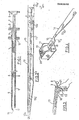
- the gun shown in FIG. 1 is an artificial insemination pistol, in particular for cattle, which comprises a tubular body 1, provided at one end with a sheath fixing head 2 which ends, itself, by an annular flange 3 for supporting the fingers, while at its other end, it offers an internal shoulder 4 into which fits one end of a seed or flake reserve 5 provided with a plunger stopper 6. It further comprises a rod -pusher 7 slidingly mounted in the body 1 so as to be able to come, at one end, to push back the plug-piston 6 and therefore to eject the seed contained in the straw 5, while at its other end, it offers a flange 8 d 'finger support.
- the body 1 and this rod 7 are, for example, made of stainless steel.
- the pistol is finally completed by a cylindrical protective sheath 4 which covers the whole of the body 1 and of the straw 5, the latter coming, by its front end, to bear on the inner face of a converging part 10 of this sheath which has an ejection orifice 11, while at its other end, the sheath is elastically clamped on a frustoconical part of the head 2, by virtue of a clamping ring 12.
- Such a disposable sheath 9 is used for each insemination operation and is threaded onto the pistol before its introduction into the animal's genital tract, its front ejection end 10 being able to stop before the cervix. or even exceed it. This sheath is discarded once the device has been removed from the animal's genital tract, so that the gun 1 is not soiled and can be used without inconvenience on another animal, covered with a new sheath.
- a protective jacket 13 which is intended to prevent the sheath 9 from collecting in the passage in the vulva and the vagina, microorganisms which it would transfer into the uterus.
- This jacket 13 is constituted by a section of cylindrical tube extruded from a very flexible and very fine material such as, for example, polyethylene, cellophane, biodegradable paper, or the combination of two of these elements, of a thick , for example 25 microns.
- This jacket has an end 13a which is practically open over its entire section and through which the gun could have been inserted inside the jacket, while its opposite end 13b is sealed.
- the end 10 of the sheath 9 of the gun abuts against the most anterior part 13c of this end 13b, the length of the jacket, between this part 13c and the end 13a, being such that it completely envelops the gun up to the height of the sheath fixing head'2, and even beyond the flange 8 if necessary, (end 13a in phantom).
- such a jacket 13 is part of a continuous and flattened extruded tube 14 constituted by the axial juxtaposition of a series of such shirts 13.
- This tube, and consequently each of the shirts 13, is flattened so as to form two overlapping layers resting on each other.
- the end 13b of each jacket is closed in a leaktight manner by joining the two layers together, by heat sealing, pulse welding, ultrasound or any other method, along a straight line very strongly inclined, with respect to the transverse direction of the jacket, for example at 75 °.
- This heat seal line 13b converges with one of the two edges 15 of the flattened jacket, but does not extend to their intersection, being interrupted by another relatively short heat seal line and oriented transversely to the jacket, which constitutes the most anterior part 13c of this closed front end 13b.
- the successive liners 13 which constitute the extruded tube and flattened 14 are juxtaposed by being all arranged in the same direction, which means that the line of fastening by heat sealing 13b, 13c of a shirt happens to be directly adjacent to the open end 13a of the next shirt, a fall of triangular shape having been eliminated during manufacture between the strongly inclined line 13b and the open open end 13a.
- each liner 13 has, near its open end 13a, two slots 16 which are parallel to the axis, main or in the axis of the cylindrical liner and are even exactly superimposed when the two layers of the liner rest on flat on top of each other.
- the cross section of the jacket 13 is relatively large and may correspond to several times that of the gun body 1 and the protective sheath 9 which covers it, so as to envelop the latter relatively freely, even at the level of the front end where the tip 10 of the sheath is surrounded with play by the converging end formed by the line 13b with the edge 15 of the shirt.
- This clearance prevents the conical tip 10 of the sheath from being "strangled" during its penetration movement, before perforation of the end of the jacket, movement causing both an axial elongation and a radial constriction which would be responsible for such strangulation; in the extreme, the latter would cause the tearing of a complete cone of material which would remain on the end of the sheath and thus penetrate through the cervix, with the risks of foreign body and corresponding contamination , which we are just trying to avoid.
- the width of the flattened jacket over the gun is of the order of three times the diameter of the latter.
- the slots 16 are arranged approximately in the middle of the width of the flattened jacket, as shown in FIGS. 2 and 5. It can therefore be seen that this double arrangement allows the gun body 1 to be placed at the inside of the jacket 13, on one of the sides of the latter, so as to be located entirely on one and even side of the assembly of the two slots 16, which will allow, as will be described later, the easy insertion of the index into both of these slots.
- the tube 14 which consists of a very large number of liners 13, succeeding each other, for example of the order of several tens, is wound axially in the form of a roller of liners called load 19, placed in a generally cylindrical charger 17, made for example of plastic or stainless steel, and which has a slot 18 parallel to its axis and out of which protrudes the end of the wound tube 14.
- This cylindrical charger 17 can be opened so as to receive the load and be placed in a dispenser box, display stand or work kit 20, which the user can place or fix at will, wherever he sees fit, in a room or on a work chest for example.
- the user introduces the index finger through the two slots 16 of the shirt, and, taking support with the thumb 21 on the collar 3 of the gun, he proceeds, using the index finger 22, to traction on the half-ring or handle 23 which then forms the part of the jacket located on the side of the slots 16, due to the easy plastic deformation of the material used.
- This traction propagates all along the jacket 13 and thus acts on the heat-sealed end 13c of the latter, so that the converging end 10 of the gun sheath punctures the latter and passes through it.
- This pierced end 13c thus being set back a few millimeters relative to the ejection orifice 11 of the sheath, the user can then make the entire pistol coated with the sheath 9 penetrate towards the cervix , and this until its end is placed in the optimal position desired for the insemination operation. During this penetration, the shirt 13 folds along the sheath 9, since it is held back behind the cervix. Thanks to this arrangement, and more particularly this possibility of pleating which has no limitation, the penetration into the interior of the uterus can be as deep as necessary.
- the user extracts the assembly and successively discards the jacket 13 and the sheath 9, the gun 1 thus being kept unsoiled and ready for a new operation.
- each jacket 24 forming part of an extruded tube 14 is formed by a transverse heat seal line 25, that is to say perpendicular to the length of the jacket.
- the slots 16 always have the same arrangement and, when withdrawing from a charger 17, the open end 13a of the jacket has already been produced during the separation of the previous jacket, beyond the thermo line -solder 25 thereof.
- the heat seal line 25a which constitutes the closed end of the jacket 24a, is inclined at approximately 45 ° relative to the axis of the jacket.
- the successive liners 24 or 24a belonging to the same extruded tube 14 are all placed in the same direction one behind the other; on the other hand, in the embodiment illustrated in FIG. 7, the sleeves 24b of the tube 14 are, two by two, grouped head to tail, so that the two heat-sealing lines 25b constituting the closed ends of the juxtaposed are these shirts.
- the two juxtaposed thermo-welding lines 25b are arranged in straight lines very strongly inclined relative to the transverse, for example at about 75 °.
- the successive jackets are torn off alternately, once along the heat-seal lines 25b and the other time along a transverse line not shown in the figure, and along which the open ends 13a of juxtaposed are two shirts.
- the sleeves 24c are also grouped two by two head to tail, but the corresponding thermo-welding lines 25c are, at each of their two ends, interrupted by a rounded 26 or a short transverse weld, joining the edge 27 of the jacket kept flat.
- the two heat-sealing lines 25c are separated by a weakening line 28 produced through the thickness of the two layers making up the jacket, for example by a succession of perforations.
- the liners 24d are also grouped two by two head to tail and the thermo-welding lines 25d have semi-circular shapes extending over the entire width of the liners and tangent to one another.
- the roll of shirts or load 19 is, once finished interchangeable and these loads 19 can be packaged or presented in the form of a continuous chain of honeycombs which are presented in groups, for example of one or more tens, as shown in fig. 10.
- the shirts 30 can be presented in unitary form, that is to say not maintained in the form of a continuous tube, these different shirts 30 constituting a stack of shirts having the same orientation and whose open ends 13a are maintained by a pinout 31, as shown for example in fig.11.
Landscapes
- Health & Medical Sciences (AREA)
- Life Sciences & Earth Sciences (AREA)
- Veterinary Medicine (AREA)
- Public Health (AREA)
- Engineering & Computer Science (AREA)
- General Health & Medical Sciences (AREA)
- Animal Behavior & Ethology (AREA)
- Heart & Thoracic Surgery (AREA)
- Zoology (AREA)
- Biomedical Technology (AREA)
- Anesthesiology (AREA)
- Vascular Medicine (AREA)
- Diabetes (AREA)
- Animal Husbandry (AREA)
- Reproductive Health (AREA)
- Wood Science & Technology (AREA)
- Hematology (AREA)
- Media Introduction/Drainage Providing Device (AREA)
- Absorbent Articles And Supports Therefor (AREA)
- Infusion, Injection, And Reservoir Apparatuses (AREA)
- Professional, Industrial, Or Sporting Protective Garments (AREA)
- Acyclic And Carbocyclic Compounds In Medicinal Compositions (AREA)
- Medicines Containing Material From Animals Or Micro-Organisms (AREA)
- Pens And Brushes (AREA)
- Wrappers (AREA)
- Catching Or Destruction (AREA)
- Packaging Of Annular Or Rod-Shaped Articles, Wearing Apparel, Cassettes, Or The Like (AREA)
Abstract
Description
- La présente invention concerne les pistolets d'action gynécologique pour animaux, tels'que les pistolets d'insémination artificielle ou de transfert ou collecte d'embryons pour le bétail ou les volailles, du type comprenant un corps tubulaire, une capacité de stockage de produit à injecter et des moyens d'éjection par l'extrémité avant du corps. Ce corps peut être complété par une gaine semi-rigide qui enveloppe le corps tubulaire et est fixée de manière amovible autour d'une extrémité de préhension de celui-ci. Cette gaine a pour but d'éviter tout contact du corps de pistolet lui-même avec l'animal et donc toute contamination postérieure d'un autre animal lors d'une nouvelle utilisation étant donné que l'on jette et remplace cette gaine après chaque opération, de sorte que le corps de pistolet peut demeurer stérile pendant un nombre illimité d'opérations.
- On connaît déjà, par exemple par les brevets français 1 224 918, 1 467 943, 1 525 336 ou 2 358 136, des pistolets d'insémination de ce type,notamment pour bovins, dans lesquels le corps est destiné à recevoir, à son extrémité avant, une réserve de produit d'insémination en forme de paillette tandis que les moyens d'éjection sont constitués par une tige-poussoir qui est montée coulissante dans ce corps, du côté de son extrémité arrière. Il est en général prévu une gaine de protection contre les contaminations externes qui s'étend pratiquement sur toute la longueur du corps et offre à son extrémité avant une partie convergeante,comportant éventuellement un manchon intérieur, contre l'intérieur de laquelle s'appuie l'extrémité avant de la paillette, cette extrémité conver- geante présentant bien entendu une ouverture d'éjection en regard de cette extrémité.
- On connaît aussi, par exemple par les brevets français 80 04 606, 80 n4 607 et 80 14 930, des pistolets de transfert, ou de simple collecte d'embryons, également pour bcvins, qui sont du même type et dans lesquels la capacité de stockage des embryons est réalisée soit sous la forme d'une paillette, comme dans le cas de l'insémination, soit, sous la forme d'une chambre intérieure ménagée à l'avant du corps, soit encore (dans le cas de la simple collecte) sous la forme d'une capacité séparée reliée à l'arrière du corps, tandis que, en cas de transfert, les moyens d'éjection sont encore constitués par une tige-poussoir montée coulissante à l'arrière du corps. Dans les différentes variantes de transfert, il peut toujours être prévu une gaine de protection contre les contaminations extérieures et qui s'étend soit sur toute la longueur du corps pour servir d'appui à l'extrémité avant de celui-ci dans le cas d'une paillette, soit le long d'une partie principale extérieure du corps,qui est réalisée télescopique, dans le cas d'une chambre interne de stockage.
- Il se trouve toutefois que de telles gaines de protection contre les contaminations externes ne luttent efficacement que contre la contamination due au passage d'un animal au suivant. Or, il est connu que vivent dans le vagin, en particulier des bovins, des mycoplasmes qui sont des micro- bactéries qui, si elles pénètrent dans l'utérus, réduisent notablement le taux de fécondation, surtout dans certaines régions géographiques où les mycoses se développent plus aisément. L'action néfaste de ces mycoplasmes dans l'utérus peut se produire malgré la présence d'anticorps spécialement secré- tés par l'utérus pour lutter contre eux. La gaine de protection risque donc de transférer de tels mycoplasmes du vagin jusque dans l'utérus.
- Le même inconvénient pourrait également se présenter dans le cas de pistolets sans gaine de protection, par exemple du type jetable (et à extrémité non rigide afin de ne pas blesser l'animal), auquel cas ce serait l'extrémité du corps lui-même qui risquerait de transférer les mycoplasmes du vagin vers l'utérus.
- C'est pourquoi l'invention a pour but de supprimer cet inconvénient en permettant 'de disposer d'un pistolet du type précité dont l'extrémité,éventuellement munie d'une gaine de protection contre les contaminations externes (d'un animal à l'autre), ne risque pas non plus, de transférer du vagin vers l'utérus de l'animal lui-même, les micro -organismes, pathogènes ou non, susceptibles de se développer ou non, qui siègent sur les parois de la vulve et du vagin et pourraient, s'ils étaient introduits dans l'utérus, provoquer des troubles néfastes, notamment de la fécondation. Ce résultat doit pouvoir être obtenu aussi bien dans la pratique de l'insémination artificielle que de la transplantation des embryons (inovulation) ou encore du prélèvement des germes qui se développent dans la glaire du vagin. Une autre condition impérative devant être respectée par la solution apportée à ce problème par l'invention, réside dans le fait que cette protection ne doit exiger, pour son application, que l'utilisation de la seule et même main qui tient le pistolet et le manoeuvre, étant donné que l'autre main et le bras se trouvent déjà introduits dans le rectum de l'animal pour palper la paroi qui avoisine le col de l'utérus et permettre une bonne localisation de celui-ci et une pénétration précise et sans blessure, de l'instrument à travers ce col.
- A cet effet, l'invention a pour objet une chemise de protection contre les contaminations pour pistolet du type précité, caractérisée en ce qu'elle est constituée par un élément cylindrique en matière souple et fine, dont une extrémité est obturée de manière étanche, mais déchirable, et dont la longueur correspond approximativement à celle de l'ensemble du pistolet, deux fentes à peu près parallèles étant ménagées à proximité de l'extrémité opposée à l'extrémité obturée.
- Grâce à cette disposition, avant usage, l'utilisateur enfile la chemise sur le corps du pistolet ( ou sur sa gaine, s'il en est prévu une) jusqu'à ce que l'extrémité de ce corps (ou de cette gaine) vienne buter contre l'extrémité obturée de cette chemise, à.la suite de quoi, il introduit l'ensemble dans le vagin de l'animal, à l'aide d'une seule main, jusqu'à ce que l'extrémité obturée de la chemise, qui retient le corps de pistolet, ait commencé à pénétrer dans le col de l'utérus ou soit sur le point de le faire. L'utilisateur passe alors l'index de la main qui tient le pistolet, dans les deux fentes prévues dans la chemise et tire alors sur la partie de la chemise qui sépare ces deux fentes et n'entoure pas le pistolet, de manière à former, du fait de la souplesse et de l'élasticité de la matière constitutive de la chemise, un demi-anneau ou anse, par lequel il applique sur la chemise une traction en prenant appui à l'aide du pouce de la même main sur le corps du pistolet, de sorte que l'extrémité de ce pistolet (ou de sa gaine) perfore l'extrémité obturée de la chemise contre laquelle elle venait en butée. A la suite de cette perforation, l'utilisateur peut introduire, toujours à l'aide de la même main, le pistolet à l'intérieur de l'utérus, et ceci jusqu'à ce que son extrémité atteigne la position optimale voulue pour l'opération à effectuer. Ainsi, pendant toute la traversée de la vulve et du vagin, le corps de pistolet (ou sa gaine) a été entièrement maintenu hors de contact avec la paroi et n'a donc pu être contaminé par les micro-organismes, alors que la chemise, une fois perforée, demeure en deçà du col de l'utérus. La protection recherchée se trouve donc obtenue et sa mise en oeuvre ne nécessite que l'utilisation de la seule et même main qui tient normalement le pistolet, tandis qu'en outre la pénétration dans l'utérus peut être aussi profonde que nécessaire puisque, du fait de sa souplesse, la chemise peut se plisser autour du pistolet au fur et à mesure de son mouvement sans, en aucune manière, limiter la course de ce dernier.
- Dans un mode de réalisation particulier de l'invention, il est prévu que l'élément cylindrique soit venu d'extrusion et soit aplati de manière à former deux couches superposées, l'extrémité obturée de cette chemise étant constituée par une solidarisation desdites couches transversalement à l'axe de l'élément cylindrique, de sorte que la fabrication de ces chemises est très aisée s'obtenant à l'aide d'un procédé simple d'extrusion à laquelle sont adjoints des organes de solidarisation, de préférence de thermosoudure, et de réalisation de fentes. On pourrait également envisager de réaliser ce tube par la superposition .at la soudure en continu ,le deux bandes de matière identique ou différente , associant par exemple, dans le cas d'une bande de matière plastique et d'une bande de papier souple, l'élasticité de l'une et l'inextensibilité de l'autre, cette association garantissant à 100% la perforation de la chemise.
- De manière particulièrement avantageuse, chaque chemise peut faire partie d'un tube extrudé continu et aplati constitué par la juxtaposition axiale d'une série de telles chemises, tandis que ce tube est enroulé axialement sous forme d'un rouleau qui est contenu dans un chargeur de forme générale cylindrique et présentant une fente par laquelle sort ledit tube, de sorte que l'utilisateur dispose d'un ensemble de chemises sous un très faible encombrement et facile à distribuer, le tube se déroulant sous une simple traction, tandis que la séparation des chemises successives-se fait par simple déchirement ou procédé de découpe.
- D'autrescaractéristiques et avantages de l'invention ressortiront de la description qui va suivre, à titre d'exemples non limitatifs et en regard des dessins annexés sur lesquels :
- - la Fig. 1 représente une vue, en coupe et avec arrachement, d'un pistolet pouvant être équipé d'une chemise conforme à l'invention ;
- - la Fig. 2 représente une vue analogue du même pistolet représenté en extérieur et revêtu d'une chemise suivant un premier mode de réalisation conforme à l'invention ;
- - la Fig. 3 illustre l'utilisation de ce pistolet muni d'une chemise de protection conforme à l'invention ;
- - la Fig. 4 représente l'ensemble d'une série de telles chemises réalisées sous forme d'un tube aplati continu présenté sous forme d'un rouleau contenu dans un chargeur
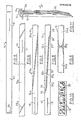
- - les Fig. 5 et 6 représentent deux réalisations différentes de chemises réalisées sous la forme d'un tube aplati en étant juxtaposées dans le même sens ;
- - les Fig. 7, 8 et 9 représentent trois autres modes de réalisation dans lesquels les chemises sont réalisées sous forme d; tubes aplatis avec juxtaposition des chemises deux par deux tête-bêche ;
- - la Fig. 10 illustre un conditionnement en chaine de rouleaux du type de la fig.4 ;
- - la Fig. 11 illustre la présentation d'une pile de chemises sous forme brochée.
- Le pistolet représenté sur la Fig. 1 est un pistolet d'insémination artificielle, notamment pour bovins, qui comprend un corps tubulaire 1,muni à une extrémité d'une tête 2 de fixation de gaine qui se termine,elle-même,par une collerette annulaire 3 d'appui des doigts, tandis qu'à son autre extrémité,il offre un épaulement intérieur 4 dans lequel vient s'emboîter une extrémité d'une réserve de semence ou paillette 5 munie d'un bouchon-piston 6. Il comprend, en outre, une tige-poussoir 7 montée coulissante dans le corps 1 de manière à pouvoir venir, à une extrémité, repousser le bouchon-piston 6 et donc éjecter la semence contenue dans la paillette 5, tandis qu'à son autre extrémité, elle offre une collerette 8 d'appui des doigts. Le corps 1 et cette tige 7 sont, par exemple, réalisés en acier inoxydable. Le pistolet est enfin complété par une gaine cylindrique de protection 4 qui recouvre l'ensemble du corps 1 et de la paillette 5, cette dernière venant, par son extrémité avant, s'appuyer sur la face intérieure d'une partie convergente 10 de cette gaine qui présente un orifice d'éjection 11, tandis qu'à son autre extrémité, la gaine est élastiquement serrée sur une partie tronconique de la tête 2, grâce à une bague de serrage 12.
- Une telle gaine 9, jetable, est utilisée pour chaque opération d'insémination et est enfilée sur le.pistolet avant son introduction dans les voies génitales de l'animal, son extrémité avant d'éjection 10 pouvant s'arrêter avant le col de l'utérus, ou même le dépasser. Cette gaine est jetée une fois l'appareil retiré des voies génitales de l'animal, de sorte que le pistolet proprement dit 1 n'est pas souillé et peut être utilisé sans inconvénient sur un autre animal , recouvert d'une nouvelle gaine.
- Comme le montre la Fig. 2, un tel pistolet, muni de sa gaine 9, se trouve enveloppé dans une chemise de protection 13 qui est destinée à éviter que la gaine 9 ne recueille au passage dans la vulve et le vagin, des micro-organismes qu'elle transférerait dans l'utérus. Cette chemise 13 est constituée par une section de tube cylindrique extrudé en une matière très souple et très fine telle que, par exemple, du polyéthylène, de la cellophane, du papier biodégradable, ou la combinaison de deux de ces éléments, d'une épaisseur, par exemple de 25 microns. Cette chemise présente une extrémité 13a qui est pratiquement ouverte sur toute sa section et par laquelle le pistolet a pu être enfilé à l'intérieur de la chemise, tandis que son extrémité opposée 13b est obturée de manière étanche. L'extrémité 10 de la gaine 9 du pistolet vient buter contre la partie la plus antérieure 13c de cette extrémité 13b, la longueur de la chemise, comprise entre cette partie 13c et l'extrémité 13a, étant telle qu'elle enveloppe entièrement le pistolet jusqu'à hauteur de la tête'2 de fixation de la gaine, et même au-delà de la collerette 8 si nécessaire, (extrémité 13a en trait mixte).
- Comme le montre plus précisément la Fig. 4, une telle chemise 13 fait partie d'un tube extrudé continu et aplati 14 constitué par la juxtaposition axiale d'une série de telles chemises 13. Ce tube,et par conséquent chacune des chemises 13,est aplati <de manière à former deux couches superposées reposant l'une sur l'autre. L'extrémité 13b de chaque chemise est obturée de manière étanche par solidarisation des deux couches entre elles, par thermo-soudure, soudure par impulsions, ultrasons ou tout autre procédé, le long d'une ligne droite très fortement inclinée, par rapport à la direction transversale de la chemise, par exemple à 75°. Cette ligne de thermo-soudure 13b converge avec l'un des deux bords 15 de la chemise aplatie, mais ne s'étend pas jusqu'à leur intersection, se trouvant interrompue par une autre ligne de thermo-soudure relativement courte et orientée transversalement à la chemise, qui constitue la partie la plus antérieure 13c de cette extrémité avant obturée 13b.
- Comme le montre également la Fig. 4, les chemises 13 successives qui constituent le tube extrudé et aplati 14 sont juxtaposées en étant toutes disposées dans le même sens, ce qui signifie que la ligne de solidarisation par thermo-soudure 13b, 13c d'une chemise se trouve être directement adjacente à l'extrémité ouverte 13a de la chemise suivante, une chute de forme triangulaire ayant été supprimée à la fabrication entre la ligne fortement inclinée 13b et l'extrémité ouverte 13a adjacente.
- Comme le montre encore la fig. 4, chaque chemise 13 présente, à proximité de son extrémité ouverte 13a, deux fentes 16 qui sont parallèles à l'axe, principal ou dans l'axe de la chemise cylindrique et sont même exactement superposées lorsque les deux couches de la chemise reposent à plat l'une sur l'autre.
- La section transversale de la chemise 13 est relativement importante et peut correspondre à plusieurs fois celle du corps de pistolet 1 et de la gaine de protection 9 qui le recouvre, de manière à envelopper ces derniers de manière relativement libre, même au niveau de l'extrémité avant où la pointe 10 de la gaine est entourée avec du jeu par l'extrémité convergente que forme la ligne 13b avec le bord 15 de la chemise. Ce jeu évite que la pointe conique 10 de la gaine ne se trouve "étranglée" pendant son mouvement de pénétration, avant perforation de l'extrémité de la chemise, mouvement provoquant à la fois une élongation axiale et un rétreint radial qui serait responsable d'un tel étranglement ; à l'extrême, ce dernier entrai- nerait l'arrachement d'un cone complet de matière qui demeurerait sur l'extrémité de la gaine et pénétrerait ainsi par le col de l'utérus, avec les risques de corps étranger et de contamination correspondants, que l'on cherche justemement à éviter.
- Dans le cas de réalisation particulière illustrée par la fig.2, la largeur de la chemise aplatie par-dessus le pistolet est de l'ordre de trois fois le diamètre de ce dernier. Par ailleurs, les fentes 16 sont disposées approximativement au milieu de la largeur de la chemise aplatie, comme le montrent les fig.2 et 5. On constate donc bien que cette double disposition permet au corps de pistolet 1 d'être placé à l'intérieur de la chemise 13 , sur l'un des côtés de cette dernière, de manière à être situé entièrement sur un et même coté de t'ensemble des deux fentes 16, de qui permettra, comme cela sera décrit par la suite, l'introduction aisée de l'index dans l'une et l'autre de ces fentes.
- Comme le montre également la fig.5, le tube 14 qui est constitué d'un très grand nombre de chemises 13, se succédant, par exemple de l'ordre de plusieurs dizaines, se trouve enroulé axialement sous forme d'un rouleau de chemises appelé charge 19, placé dans un chargeur de forme générale cylindrique 17, réalisé par exemple en matière plastique ou en acier inoxydable, et qui présente une fente 18 parallèle à son axe et hors de laquelle fait saillie l'extrémité du tube enroulé 14. Ce chargeur cylindrique 17 peut s'ouvrir de façon à recevoir la charge et être placé dans un boitier distributeur, présentoir ou trousse de travail 20, que l'utilisateur peut placer ou fixer à volonté, où bon lui semble, dans un local ou sur une caisse de travail par exemple.
- L'utilisation des chemises de protection ainsi décrites est la suivante :
- L'extrémité 13a d'un rouleau de chemises dépassant hors de la fente 18 du chargeur, l'utilisateur saisit cette dernière et procède à une traction jusqu'à ce que l'ensemble d'une chemise 13 en soit issue, à la suite de quoi, il déchire ou coupe cette chemise complète au-delà de la thermo-soudure extrême 13c, complétant ainsi de ce fait, l'ouverture 13a de la chemise suivante. Il introduit alors l'ensemble du pistolet 1 et de la paillette 5 déjà recouverts préalablement par la gaine 9, à l'intérieur de cette chemise 13 et à l'aide de l'ouverture extrême d'entrée 13a, ceci jusqu'à ce que l'extrémité 10 de la gaine vienne en butée contre la ligne extrême de thermo-soudure 13c. Dans cette position, les deux collerettes 3 et 8 du pistolet ainsi que la bague 12, peuvent demeurer à l'extérieur de la chemise 13 au-delà de son ouverture 13a, tandis que le pistolet est placé sur l'un des côtés de la chemise, de manière à ne pas s'interposer entre les deux fentes 16.
- L'utilisateur introduit alors l'ensemble ainsi constitué par le pistolet et la chemise 13, dans les voies génitales de l'animal, en traversant successivement la vulve et le vagin, et ceci jusqu'à ce que l'extrémité avant 13c de la chemise soit sensiblement en regard du col de l'utérus, ce positionnement s'effectuant à la manière connue grâce à la mise en place de l'autre main dans le rectum de l'animal.
- Se servant alors de la main à l'aide de laquelle il a mis en place le pistolet revêtu d2 sa chemise. l'utilisateur introduit l'index à travers les deux fentes 16 de la chemise, et, prenant appui à l'aide du pouce 21 sur la collerette 3 du pistolet, il procède, à l'aide de l'index 22, à une traction sur le demi-anneau ou anse 23 que forme alors la partie de la chemise située sur le côté des fentes 16, en raison de la déformation plastique aisée du matériau utilisé. Cette traction se propage tout le long de la chemise 13 et agit ainsi sur l'extrémité thermo-soudée 13c de cette dernière, de sorte que l'extrémité convergente 10 de la gaine du pistolet perfore cette dernière et la traverse.
- Cette extrémité 13c percée se trouvant ainsi en retrait de quelques millimètres par rapport à l'orifice d'éjection 11 de la gaine, l'utilisateur peut alors faire pénétrer l'ensemble du pistolet revêtu de la gaine 9 vers le col de l'utérus, et ceci jusqu'à ce que son extrémité se trouve placée dans la position optimale souhaitée pour l'opération d'insémination. Pendant cette pénétration, la chemise 13 se plisse le long de la gaine 9, puisque se trouvant retenue en arrière du col de l'utérus. Grâce à cette disposition, et plus particulièrement cette possibilité de plissage qui ne présente aucune limitation, la pénétration à l'intérieur de l'utérus peut être aussi profonde que nécessaire.
- Une fois l'insémination effectuée, l'utilisateur extrait l'ensemble et jette successivement la chemise 13 et la gaine 9, le pistolet 1 se trouvant ainsi maintenu non souillé et prêt pour une nouvelle opération.
- Dans la variante de réalisation illustrée par la fig. 5, l'extrémité obturée de chaque chemise 24 faisant partie d'un tube extrudé 14, se trouve constituée par une ligne de thermo-soudure 25 transversale, c'est à dire perpendiculaire à la longueur de la chemise. Les fentes 16 présentent toujours la même disposition et, lors du prélèvement à partir d'un chargeur 17, l'extrémité ouverte 13a de la chemise a déjà été réalisée lors de la séparation de la chemise précédente, au-delà de la ligne de thermo-soudure 25 de celle-ci.
- Dans la variante de réalisation illustrée par la fig. 6, la ligne de thermo-soudure 25a qui constitue l'extrémité obturée de la chemise 24a, se trouve inclinée à approximativement 45° par rapport à l'axe de la chemise.
- Dans l'une et l'autre des deux réalisations précédentes, les chemises successives 24 ou 24a appartenant à un même tube extrudé 14 sont toutes diposées dans le même sens les unes derrière les autres ; par contre, dans la réalisation illustrée par la fig.7 , les chemises 24b du tube 14 sont, deux par deux, regroupées tête-bêche, de manière à ce que soient juxtaposées les deux lignes de thermo-soudure 25b constituant les extrémités obturées de ces chemises. Les deux lignes de thermo-soudure 25b juxtaposées sont disposées suivant des lignes droites très fortement inclinées par rapport à la transversale, par exemple à environ 75°. Dans ce cas, l'arrachement des chemises successives se fait alternativement, une fois le long des lignes de thermo-soudure 25b et l'autre fois suivant une ligne transversale non représentée sur la figure,et suivant laquelle sont juxtaposées les extrémités ouvertes 13a de deux chemises.
- Dans la variante de réalisation de la fig.8, les.chemises 24c sont également regroupées deux par deux tête-bêche, mais les lignes de thermo-soudure correspondantes 25c sont, à chacune de leurs deux extrémités, interrompues par un arrondi 26 ou une courte soudure transversale, se raccordant au bord 27 de la chemise maintenue à plat. En outre, les deux lignes de thermo-soudure 25c sont séparées par une ligne d'affaiblissement 28 réalisée à travers l'épaisseur des deux couches constitutives à la chemise, par exemple par une succession de perforations.
- Dans la variante de la fig. 9 , les chemises 24d sont également regroupées deux par deux tête - bêche et les lignes de thermo-soudure 25d présentent des formes semi-circulaires s'étendant sur toute la largeur des chemises et tangentes entre elles.
- Le rouleau de chemises ou charge 19 est, une fois terminé interchangeable et ces charges 19 peuvent être conditionnées ou présentées sous forme d'une chaîne continue d'alvéo- lessuccessifs29 qui se présentent par groupes, par exemple d'une ou plusieurs dizaines, comme le montre la fig.10.
- Dans une variante de conditionnement, les chemises 30 peuvent être présentées sous forme unitaire, c'est à dire non maintenues sous forme d'un tube continu, ces différentes chemises 30 constituant une pile de chemises présentant la même orientation et dont les extrémités ouvertes 13a sont maintenues par un brochage 31, ainsi que représenté par exemple sur la fig.11.
Claims (20)
Priority Applications (1)
| Application Number | Priority Date | Filing Date | Title |
|---|---|---|---|
| AT83400691T ATE15758T1 (de) | 1982-04-29 | 1983-04-01 | Schutzhuelle gegen interne kontamination fuer eine gynaekologische pistole, insbesondere fuer rinder. |
Applications Claiming Priority (2)
| Application Number | Priority Date | Filing Date | Title |
|---|---|---|---|
| FR8207420 | 1982-04-29 | ||
| FR8207420A FR2525894A1 (fr) | 1982-04-29 | 1982-04-29 | Chemise de protection contre les contaminations internes pour pistolet d'action gynecologique, notamment pour bovins |
Publications (2)
| Publication Number | Publication Date |
|---|---|
| EP0093630A1 true EP0093630A1 (fr) | 1983-11-09 |
| EP0093630B1 EP0093630B1 (fr) | 1985-09-25 |
Family
ID=9273544
Family Applications (1)
| Application Number | Title | Priority Date | Filing Date |
|---|---|---|---|
| EP83400691A Expired EP0093630B1 (fr) | 1982-04-29 | 1983-04-01 | Chemise de protection contre les contaminations internes pour pistolet gynécologique, notamment pour bovins |
Country Status (7)
| Country | Link |
|---|---|
| US (1) | US4453936A (fr) |
| EP (1) | EP0093630B1 (fr) |
| JP (1) | JPS6057860B2 (fr) |
| AT (1) | ATE15758T1 (fr) |
| CA (1) | CA1205336A (fr) |
| DE (1) | DE3360869D1 (fr) |
| FR (1) | FR2525894A1 (fr) |
Cited By (7)
| Publication number | Priority date | Publication date | Assignee | Title |
|---|---|---|---|---|
| FR2606995A1 (fr) * | 1986-04-23 | 1988-05-27 | Simmet Ludwig | Dispositif d'injection pour injecter un produit notamment pour l'insemination artificielle ou la transmission d'embryons, notamment destine aux animaux |
| FR2609885A1 (fr) * | 1987-01-22 | 1988-07-29 | Cassou Robert | Instrument pour l'insemination artificielle, le transfert d'embryons ou le prelevement de liquides folliculaires chez les mammiferes |
| FR2685191A1 (fr) * | 1991-12-20 | 1993-06-25 | Coudouneau Lucile | Dispositif pour transferer des embryons ou pratiquer l'insemination artificielle dans des especes animales. |
| FR2706123A1 (fr) * | 1993-06-08 | 1994-12-16 | Gestion Engineering Et | Sonde à porte-écouvillon de prélèvement à usage médical et vétérinaire. |
| DE29505177U1 (de) * | 1995-03-27 | 1995-05-18 | Kisfeld, Alfons, 48691 Vreden | Vorrichtung zur künstlichen Befruchtung von Tieren, insbesondere Sauen |
| WO2010034871A1 (fr) * | 2008-09-26 | 2010-04-01 | Universidad De Murcia | Dispositif et procédé d'introduction ou d'obtention d'un fluide avec des gamètes, embryons ou tout autre type de solution à l'intérieur des trompes utérines d'une truie |
| WO2015185863A1 (fr) | 2014-06-04 | 2015-12-10 | Elexinn | Dispositif perfectionne de transfert atraumatique de materiel ou substance a but reproductif, therapeutique ou diagnostique dans des mammiferes femelles |
Families Citing this family (25)
| Publication number | Priority date | Publication date | Assignee | Title |
|---|---|---|---|---|
| JPS61117670A (ja) * | 1984-11-13 | 1986-06-05 | Fujitsu Ltd | 文字切り出し処理方式 |
| US4731059A (en) * | 1986-10-14 | 1988-03-15 | Medical Safety Products, Inc. | Combination needle shield/needle guard device positively locked onto detachable needle assemblies for an evacuated blood collection system and a hypodermic syringe |
| JP2540168B2 (ja) * | 1987-09-25 | 1996-10-02 | 三菱電機株式会社 | ビ―ム偏向位置補正装置 |
| US4898586A (en) * | 1987-11-19 | 1990-02-06 | The Academy Of Applied Science | Suction catheter and storage holder and package |
| JP2651228B2 (ja) * | 1988-12-28 | 1997-09-10 | 旭硝子株式会社 | 車両用硬質板状物インサートモジュールアッシーウインドの製造方法 |
| JPH0742401Y2 (ja) * | 1990-02-01 | 1995-10-04 | 株式会社町田製作所 | 内視鏡カバー |
| US5217114A (en) * | 1991-05-15 | 1993-06-08 | Applied Vascular Devices, Inc. | Catheter package |
| BR9405395A (pt) * | 1993-06-04 | 1999-09-08 | Kwahak Internacional Co Ltda | Dispositivo para inseminação artificial e para transferência de embrião. |
| US5407354A (en) * | 1993-12-03 | 1995-04-18 | Gull Laboratories, Inc. | Anti-microbial apparatus and method for dental handpieces |
| WO1996035384A1 (fr) * | 1995-05-09 | 1996-11-14 | Curators Of The University Of Missouri | Systeme d'injection d'un fluide dans l'uterus d'un animal |
| US5558636A (en) * | 1995-05-09 | 1996-09-24 | Curators Of The University Of Missouri | Method of effecting embryo transplant |
| CN1055669C (zh) * | 1996-11-01 | 2000-08-23 | 中国科学院化学研究所 | 一种用硅酮树脂改性的氧化镁粉末及其制备方法 |
| US6511415B1 (en) | 2000-11-03 | 2003-01-28 | Continental Plastic Corp. | Device for trans-cervical artificial insemination and embryo transfer |
| US7175590B2 (en) * | 2001-11-01 | 2007-02-13 | Continental Plastic Corp. | Apparatus for trans-cervical artificial insemination and embryo transfer |
| US7241261B2 (en) * | 2002-05-10 | 2007-07-10 | Continental Plastic Corp. | Dual use syringe |
| US7189200B2 (en) * | 2004-10-13 | 2007-03-13 | Sheng-Jui Chen | Animal-use artificial inseminator |
| US8323178B2 (en) * | 2006-04-28 | 2012-12-04 | Ainley Jr Frank | Animal insemination sheath and methods of use |
| US7344492B2 (en) * | 2006-04-28 | 2008-03-18 | Ainley Jr Frank | Animal insemination sheath |
| KR200457621Y1 (ko) | 2009-02-04 | 2011-12-28 | 대한민국 | 가축 배설물 커버 |
| US20110192511A1 (en) * | 2010-02-05 | 2011-08-11 | William Charles Marrone | Protective sleeve for windshield wiper |
| CN105125314A (zh) * | 2014-05-28 | 2015-12-09 | 蒋如明 | 一种用于马和驴输精用的多管输精枪 |
| US10182896B2 (en) | 2016-03-08 | 2019-01-22 | Frank Ainley | Animal insemination sheath and methods of use |
| US11103336B2 (en) | 2016-03-08 | 2021-08-31 | Frank Ainley | Animal insemination and in-vitro fertilization sheath, cap and methods of use |
| HUE063862T2 (hu) | 2016-06-29 | 2024-02-28 | Hollister Inc | Lezárt kamrájú vizelet katéter |
| CN107260359B (zh) * | 2017-07-12 | 2023-05-23 | 广西壮族自治区畜牧研究所 | 一种应用于牛的手臂保护器 |
Citations (5)
| Publication number | Priority date | Publication date | Assignee | Title |
|---|---|---|---|---|
| FR1344427A (fr) * | 1962-10-17 | 1963-11-29 | Mode de constitution et de mise en service de sac ou sachet | |
| FR1434411A (fr) * | 1965-02-27 | 1966-04-08 | Procédé de fabrication d'un emballage semi-rigide pour produits liquides, pulvérulents ou autres | |
| DE2435790A1 (de) * | 1974-07-25 | 1976-02-12 | Simmet Ludwig Dr Med Vet | Besamungsgeraet |
| FR2386312A1 (fr) * | 1977-04-08 | 1978-11-03 | Kendall & Co | Ensemble de sondage, notamment pour le prelevement d'urine |
| FR2468522A1 (fr) * | 1979-11-05 | 1981-05-08 | Henriet Jacques | Boitier-distributeur pour articles se presentant sous forme de feuilles ou de sacs |
Family Cites Families (6)
| Publication number | Priority date | Publication date | Assignee | Title |
|---|---|---|---|---|
| US2616424A (en) * | 1950-05-12 | 1952-11-04 | John W Brown | Medication unit |
| US2691982A (en) * | 1952-10-18 | 1954-10-19 | Jones John Leslie | Disposable applicator |
| US3894540A (en) * | 1973-10-09 | 1975-07-15 | Bonner F J Jun | Catheter |
| US4252131A (en) * | 1978-04-17 | 1981-02-24 | American Home Products Corporation | Catheter for measuring intrauterine pressure |
| FR2450102A1 (fr) * | 1979-03-02 | 1980-09-26 | Cassou Robert | Dispositif d'insemination artificielle, notamment pour porcins |
| US4329995A (en) * | 1980-08-29 | 1982-05-18 | Board Of Regents, The University Of Texas System | Catheter for nasotracheal aspiration of uncontaminated sputum specimens |
-
1982
- 1982-04-29 FR FR8207420A patent/FR2525894A1/fr active Granted
- 1982-09-28 US US06/425,286 patent/US4453936A/en not_active Expired - Lifetime
-
1983
- 1983-04-01 EP EP83400691A patent/EP0093630B1/fr not_active Expired
- 1983-04-01 AT AT83400691T patent/ATE15758T1/de not_active IP Right Cessation
- 1983-04-01 DE DE8383400691T patent/DE3360869D1/de not_active Expired
- 1983-04-07 CA CA000425442A patent/CA1205336A/fr not_active Expired
- 1983-04-25 JP JP58073693A patent/JPS6057860B2/ja not_active Expired
Patent Citations (5)
| Publication number | Priority date | Publication date | Assignee | Title |
|---|---|---|---|---|
| FR1344427A (fr) * | 1962-10-17 | 1963-11-29 | Mode de constitution et de mise en service de sac ou sachet | |
| FR1434411A (fr) * | 1965-02-27 | 1966-04-08 | Procédé de fabrication d'un emballage semi-rigide pour produits liquides, pulvérulents ou autres | |
| DE2435790A1 (de) * | 1974-07-25 | 1976-02-12 | Simmet Ludwig Dr Med Vet | Besamungsgeraet |
| FR2386312A1 (fr) * | 1977-04-08 | 1978-11-03 | Kendall & Co | Ensemble de sondage, notamment pour le prelevement d'urine |
| FR2468522A1 (fr) * | 1979-11-05 | 1981-05-08 | Henriet Jacques | Boitier-distributeur pour articles se presentant sous forme de feuilles ou de sacs |
Cited By (13)
| Publication number | Priority date | Publication date | Assignee | Title |
|---|---|---|---|---|
| FR2606995A1 (fr) * | 1986-04-23 | 1988-05-27 | Simmet Ludwig | Dispositif d'injection pour injecter un produit notamment pour l'insemination artificielle ou la transmission d'embryons, notamment destine aux animaux |
| FR2609885A1 (fr) * | 1987-01-22 | 1988-07-29 | Cassou Robert | Instrument pour l'insemination artificielle, le transfert d'embryons ou le prelevement de liquides folliculaires chez les mammiferes |
| EP0278823A1 (fr) * | 1987-01-22 | 1988-08-17 | Robert Cassou | Instrument pour l'insémination artificielle, le transfert d'embryons, ou le prélèvement de liquides folliculaires chez le mammifères |
| US4846785A (en) * | 1987-01-22 | 1989-07-11 | Robert Cassou | Instrument for artificial insemination, embryo transfer or sampling follicular liquids in mammals |
| FR2685191A1 (fr) * | 1991-12-20 | 1993-06-25 | Coudouneau Lucile | Dispositif pour transferer des embryons ou pratiquer l'insemination artificielle dans des especes animales. |
| FR2706123A1 (fr) * | 1993-06-08 | 1994-12-16 | Gestion Engineering Et | Sonde à porte-écouvillon de prélèvement à usage médical et vétérinaire. |
| DE29505177U1 (de) * | 1995-03-27 | 1995-05-18 | Kisfeld, Alfons, 48691 Vreden | Vorrichtung zur künstlichen Befruchtung von Tieren, insbesondere Sauen |
| EP0739612A3 (fr) * | 1995-03-27 | 1997-03-05 | Alfons Kisfeld | Dispositif d'insémination artificielle de truies |
| WO2010034871A1 (fr) * | 2008-09-26 | 2010-04-01 | Universidad De Murcia | Dispositif et procédé d'introduction ou d'obtention d'un fluide avec des gamètes, embryons ou tout autre type de solution à l'intérieur des trompes utérines d'une truie |
| ES2348528A1 (es) * | 2008-09-26 | 2010-12-09 | Universidad De Murcia | Dispositivo y procedimiento de introduccion u obtencion de un fluido con gametos, embriones o cualquier otro tipo de solucion del interior del oviducto de una cerda. |
| CN102223854A (zh) * | 2008-09-26 | 2011-10-19 | 穆尔西亚大学 | 用于在母猪的输卵管中引入和获得含有配子、胚胎、或任何其他类型溶液的流体的装置和方法 |
| US9277981B2 (en) | 2008-09-26 | 2016-03-08 | Universidad De Murcia | Device and method for inserting or obtaining a fluid with gametes, embryos or any other type of solution in the oviduct of a sow |
| WO2015185863A1 (fr) | 2014-06-04 | 2015-12-10 | Elexinn | Dispositif perfectionne de transfert atraumatique de materiel ou substance a but reproductif, therapeutique ou diagnostique dans des mammiferes femelles |
Also Published As
| Publication number | Publication date |
|---|---|
| FR2525894B1 (fr) | 1985-01-18 |
| US4453936A (en) | 1984-06-12 |
| EP0093630B1 (fr) | 1985-09-25 |
| FR2525894A1 (fr) | 1983-11-04 |
| DE3360869D1 (en) | 1985-10-31 |
| ATE15758T1 (de) | 1985-10-15 |
| JPS5955A (ja) | 1984-01-05 |
| CA1205336A (fr) | 1986-06-03 |
| JPS6057860B2 (ja) | 1985-12-17 |
Similar Documents
| Publication | Publication Date | Title |
|---|---|---|
| EP0093630B1 (fr) | Chemise de protection contre les contaminations internes pour pistolet gynécologique, notamment pour bovins | |
| EP1973592B1 (fr) | Seringue hypodermique preremplie equipee d'un dispositif de bouchage | |
| CA2093734C (fr) | Sonde d'insemination adaptable a un sachet-dose pour semence animale | |
| EP0718191B1 (fr) | Machine d'emballage pour doses prêtes à l'emploi, de semence animale, et dose de semence, réalisée par cette machine | |
| CH634998A5 (fr) | Appareil aseptique de catheterisme uretral. | |
| CA2209421C (fr) | Sachet de conditionnement de substances liquides biologiques a ouverture pelable pour introduction de canules, tubes et sondes | |
| FR2900327A1 (fr) | Gaine pour pistolet d'insemination artificielle, procede de fabrication d'une telle gaine, et procede d'insemination artificielle | |
| FR2558847A1 (fr) | Dispositif et procede de controle microbiologique de liquides | |
| EP1317224B1 (fr) | Sachet de conditionnement de substance a canule integree et bande constituee de tels sachets | |
| EP0527676B1 (fr) | Buse d'injection à usage unique pour machine de remplissage de paillettes, notamment pour l'insémination artificielle d'animaux et conservation de produits biologiques | |
| EP2196170B1 (fr) | Sachet et bande de sachets pour le conditionnement d'une substance biologique liquide, telle que de la semence animale | |
| EP2140834B1 (fr) | Instrument de transfert intra-utérin par la voie naturelle vagino-utérine | |
| EP2925255B1 (fr) | Gaine sanitaire pour seringue d'insémination par paillette et son procédé de fabrication | |
| FR2841789A1 (fr) | Dispositif de preparation d'un produit pharmaceutique ou medicamenteux notamment injectable | |
| EP1053727B1 (fr) | Instrument manuel de curetage et son procédé de fabrication | |
| FR2814968A1 (fr) | Dispositif distributeur avec buse integrale et capuchon | |
| WO2012072926A1 (fr) | Sonde d'insemination artificielle adaptee pour contenir de la semence animale liquide et de la semence animale encapsulee | |
| EP3242695B1 (fr) | Dispositif pour acte médical comprenant d'un côté un trocart et de l'autre côté une canule | |
| FR2686247A1 (fr) | Paillette destinee a recevoir une substance biologique. | |
| CH453198A (fr) | Emballage pour matières pâteuses et son procédé de fabrication | |
| WO2004078062A1 (fr) | Procede de transfert pour une paillette, conduit pour la mise en oeuvre de ce procede et instrument comportant ce donduit | |
| BE660681A (fr) | ||
| FR2820029A1 (fr) | Sachet et bande de sachets de conditionnement de substance, a canule et embout integres | |
| FR2778843A1 (fr) | Sachet de conditionnement d'une subtance biologique liquide et bande formee d'une juxtaposition de tels sachets | |
| FR2821267A1 (fr) | Sachet de conditionnement de semence, son procede de remplissage et procede d'insemination en faisant usage |
Legal Events
| Date | Code | Title | Description |
|---|---|---|---|
| PUAI | Public reference made under article 153(3) epc to a published international application that has entered the european phase |
Free format text: ORIGINAL CODE: 0009012 |
|
| AK | Designated contracting states |
Designated state(s): AT BE CH DE GB IT LI LU NL SE |
|
| 17P | Request for examination filed |
Effective date: 19830930 |
|
| ITF | It: translation for a ep patent filed | ||
| GRAA | (expected) grant |
Free format text: ORIGINAL CODE: 0009210 |
|
| AK | Designated contracting states |
Designated state(s): AT BE CH DE GB IT LI LU NL SE |
|
| REF | Corresponds to: |
Ref document number: 15758 Country of ref document: AT Date of ref document: 19851015 Kind code of ref document: T |
|
| REF | Corresponds to: |
Ref document number: 3360869 Country of ref document: DE Date of ref document: 19851031 |
|
| PLBE | No opposition filed within time limit |
Free format text: ORIGINAL CODE: 0009261 |
|
| STAA | Information on the status of an ep patent application or granted ep patent |
Free format text: STATUS: NO OPPOSITION FILED WITHIN TIME LIMIT |
|
| 26N | No opposition filed | ||
| ITTA | It: last paid annual fee | ||
| EPTA | Lu: last paid annual fee | ||
| EAL | Se: european patent in force in sweden |
Ref document number: 83400691.8 |
|
| PGFP | Annual fee paid to national office [announced via postgrant information from national office to epo] |
Ref country code: LU Payment date: 19960401 Year of fee payment: 14 |
|
| PGFP | Annual fee paid to national office [announced via postgrant information from national office to epo] |
Ref country code: AT Payment date: 19960424 Year of fee payment: 14 |
|
| PGFP | Annual fee paid to national office [announced via postgrant information from national office to epo] |
Ref country code: CH Payment date: 19960501 Year of fee payment: 14 |
|
| PG25 | Lapsed in a contracting state [announced via postgrant information from national office to epo] |
Ref country code: LU Free format text: LAPSE BECAUSE OF NON-PAYMENT OF DUE FEES Effective date: 19970401 Ref country code: AT Effective date: 19970401 |
|
| PG25 | Lapsed in a contracting state [announced via postgrant information from national office to epo] |
Ref country code: LI Free format text: LAPSE BECAUSE OF NON-PAYMENT OF DUE FEES Effective date: 19970430 Ref country code: CH Free format text: LAPSE BECAUSE OF NON-PAYMENT OF DUE FEES Effective date: 19970430 |
|
| REG | Reference to a national code |
Ref country code: CH Ref legal event code: PL |
|
| PGFP | Annual fee paid to national office [announced via postgrant information from national office to epo] |
Ref country code: NL Payment date: 20010315 Year of fee payment: 19 |
|
| PGFP | Annual fee paid to national office [announced via postgrant information from national office to epo] |
Ref country code: SE Payment date: 20010319 Year of fee payment: 19 |
|
| PGFP | Annual fee paid to national office [announced via postgrant information from national office to epo] |
Ref country code: GB Payment date: 20010327 Year of fee payment: 19 |
|
| PGFP | Annual fee paid to national office [announced via postgrant information from national office to epo] |
Ref country code: DE Payment date: 20010409 Year of fee payment: 19 |
|
| PGFP | Annual fee paid to national office [announced via postgrant information from national office to epo] |
Ref country code: BE Payment date: 20010514 Year of fee payment: 19 |
|
| REG | Reference to a national code |
Ref country code: GB Ref legal event code: IF02 |
|
| PG25 | Lapsed in a contracting state [announced via postgrant information from national office to epo] |
Ref country code: GB Free format text: LAPSE BECAUSE OF NON-PAYMENT OF DUE FEES Effective date: 20020401 |
|
| PG25 | Lapsed in a contracting state [announced via postgrant information from national office to epo] |
Ref country code: SE Free format text: LAPSE BECAUSE OF NON-PAYMENT OF DUE FEES Effective date: 20020402 |
|
| PG25 | Lapsed in a contracting state [announced via postgrant information from national office to epo] |
Ref country code: BE Free format text: LAPSE BECAUSE OF NON-PAYMENT OF DUE FEES Effective date: 20020430 |
|
| PG25 | Lapsed in a contracting state [announced via postgrant information from national office to epo] |
Ref country code: NL Free format text: LAPSE BECAUSE OF NON-PAYMENT OF DUE FEES Effective date: 20021101 Ref country code: DE Free format text: LAPSE BECAUSE OF NON-PAYMENT OF DUE FEES Effective date: 20021101 |
|
| EUG | Se: european patent has lapsed |
Ref document number: 83400691.8 |
|
| GBPC | Gb: european patent ceased through non-payment of renewal fee |
Effective date: 20020401 |
|
| NLV4 | Nl: lapsed or anulled due to non-payment of the annual fee |
Effective date: 20021101 |