EP0093662A2 - Orientierungsapparat für Sonnenkollektor - Google Patents
Orientierungsapparat für Sonnenkollektor Download PDFInfo
- Publication number
- EP0093662A2 EP0093662A2 EP83400847A EP83400847A EP0093662A2 EP 0093662 A2 EP0093662 A2 EP 0093662A2 EP 83400847 A EP83400847 A EP 83400847A EP 83400847 A EP83400847 A EP 83400847A EP 0093662 A2 EP0093662 A2 EP 0093662A2
- Authority
- EP
- European Patent Office
- Prior art keywords
- screw
- tube
- nut
- rotation
- mirror
- Prior art date
- Legal status (The legal status is an assumption and is not a legal conclusion. Google has not performed a legal analysis and makes no representation as to the accuracy of the status listed.)
- Granted
Links
- 229920002994 synthetic fiber Polymers 0.000 claims description 5
- 230000001681 protective effect Effects 0.000 claims description 2
- 238000000605 extraction Methods 0.000 claims 1
- 238000006073 displacement reaction Methods 0.000 description 4
- 239000012530 fluid Substances 0.000 description 4
- 230000005540 biological transmission Effects 0.000 description 2
- 230000002427 irreversible effect Effects 0.000 description 2
- 239000004677 Nylon Substances 0.000 description 1
- 239000012141 concentrate Substances 0.000 description 1
- 239000003822 epoxy resin Substances 0.000 description 1
- -1 for example Polymers 0.000 description 1
- 239000007788 liquid Substances 0.000 description 1
- 238000005461 lubrication Methods 0.000 description 1
- 238000012423 maintenance Methods 0.000 description 1
- 230000007246 mechanism Effects 0.000 description 1
- 239000002184 metal Substances 0.000 description 1
- 239000007769 metal material Substances 0.000 description 1
- 229920001778 nylon Polymers 0.000 description 1
- 230000000737 periodic effect Effects 0.000 description 1
- 230000002093 peripheral effect Effects 0.000 description 1
- 239000004033 plastic Substances 0.000 description 1
- 229920000647 polyepoxide Polymers 0.000 description 1
- 230000002441 reversible effect Effects 0.000 description 1
Images
Classifications
-
- F—MECHANICAL ENGINEERING; LIGHTING; HEATING; WEAPONS; BLASTING
- F15—FLUID-PRESSURE ACTUATORS; HYDRAULICS OR PNEUMATICS IN GENERAL
- F15B—SYSTEMS ACTING BY MEANS OF FLUIDS IN GENERAL; FLUID-PRESSURE ACTUATORS, e.g. SERVOMOTORS; DETAILS OF FLUID-PRESSURE SYSTEMS, NOT OTHERWISE PROVIDED FOR
- F15B15/00—Fluid-actuated devices for displacing a member from one position to another; Gearing associated therewith
- F15B15/02—Mechanical layout characterised by the means for converting the movement of the fluid-actuated element into movement of the finally-operated member
- F15B15/06—Mechanical layout characterised by the means for converting the movement of the fluid-actuated element into movement of the finally-operated member for mechanically converting rectilinear movement into non- rectilinear movement
- F15B15/068—Mechanical layout characterised by the means for converting the movement of the fluid-actuated element into movement of the finally-operated member for mechanically converting rectilinear movement into non- rectilinear movement the motor being of the helical type
-
- F—MECHANICAL ENGINEERING; LIGHTING; HEATING; WEAPONS; BLASTING
- F24—HEATING; RANGES; VENTILATING
- F24S—SOLAR HEAT COLLECTORS; SOLAR HEAT SYSTEMS
- F24S30/00—Arrangements for moving or orienting solar heat collector modules
- F24S30/40—Arrangements for moving or orienting solar heat collector modules for rotary movement
- F24S30/42—Arrangements for moving or orienting solar heat collector modules for rotary movement with only one rotation axis
- F24S30/422—Vertical axis
-
- F—MECHANICAL ENGINEERING; LIGHTING; HEATING; WEAPONS; BLASTING
- F24—HEATING; RANGES; VENTILATING
- F24S—SOLAR HEAT COLLECTORS; SOLAR HEAT SYSTEMS
- F24S25/00—Arrangement of stationary mountings or supports for solar heat collector modules
- F24S25/10—Arrangement of stationary mountings or supports for solar heat collector modules extending in directions away from a supporting surface
-
- Y—GENERAL TAGGING OF NEW TECHNOLOGICAL DEVELOPMENTS; GENERAL TAGGING OF CROSS-SECTIONAL TECHNOLOGIES SPANNING OVER SEVERAL SECTIONS OF THE IPC; TECHNICAL SUBJECTS COVERED BY FORMER USPC CROSS-REFERENCE ART COLLECTIONS [XRACs] AND DIGESTS
- Y02—TECHNOLOGIES OR APPLICATIONS FOR MITIGATION OR ADAPTATION AGAINST CLIMATE CHANGE
- Y02E—REDUCTION OF GREENHOUSE GAS [GHG] EMISSIONS, RELATED TO ENERGY GENERATION, TRANSMISSION OR DISTRIBUTION
- Y02E10/00—Energy generation through renewable energy sources
- Y02E10/40—Solar thermal energy, e.g. solar towers
- Y02E10/47—Mountings or tracking
Definitions
- the present invention relates to a device for orienting a solar collector as a function of the apparent movement of the sun.
- Solar energy can be recovered in the form of heat by using a concave mirror intended to concentrate the rays collected towards a hearth where can be placed, for example, a boiler.
- a concave mirror intended to concentrate the rays collected towards a hearth where can be placed, for example, a boiler.
- the concave mirror must follow the apparent movements of the sun, it is necessary to provide a device for orienting the mirror in azimuth and a device for orienting the mirror in elevation.
- These orientation devices must ensure precise movement and positioning of the mirror in all circumstances, and in particular despite the varied actions of the wind on the entire structure.
- These devices must also be irreversible, that is to say that a direct action on the mirror must not disturb its position.
- the devices must be simple, easy to install on the site, and must retain all their qualities despite being exposed to the weather.
- the orientation devices currently known are relatively complex, and include delicate mechanisms which require periodic maintenance.
- the present invention aims to overcome these drawbacks.
- the invention therefore relates to a solar collector comprising a concave mirror mounted on a support movable in rotation about an axis of rotation, and comprising an orientation device controlling the angular position of the mirror around this axis of rotation.
- the orientation device consists of a screw mounted along the axis of rotation of the mirror, connected to said movable support in rotation of the mirror, of a nut movable in translation cooperating with the screw, and a double-acting cylinder controlling the translational movements of the nut in order to consequently control the orientation of the mirror.
- the screw is made of a metallic material
- the nut is made of a molded synthetic material.
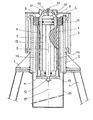
- the single figure shows, in longitudinal section, a device orientation according to the invention.
- the screw 5 has the shape of a tube whose cylindrical outer face comprises helical grooves 6 and whose cylindrical inner face 7 constitutes the working cylinder of a double action cylinder.
- This cylinder therefore comprises a piston 8 which can slide inside the bore 7 of the screw 5, under the action of a control fluid which can be brought into the working cylinder.
- the piston 8 is connected to a rod 9 which opens into the lower part of the working cylinder 7.
- the working cylinder 7 is closed upwards by a sealed radial wall 10 and downwards by another sealed radial wall 11 tightly traversed by the rod 9.
- the outer end 12 of the cylinder rod is connected to a radial plate 13, and at the periphery of this plate 13 are fixed rigid parts 14 which extend longitudinally in space between the rigid tube 2 and the screw-forming part 5.
- These rigid parts 14 are fixed by their upper part to a nut 15 which is screwed onto the screw 5 and which is subjected to sliding only longitudinally inside the tube 2 thanks to guide parts 16 extending longitudinally on the internal face of the tube 2 and coming to engage in corresponding notches formed on the peripheral part of the nut 15.
- the orientation device which has just been described operates in the following manner.
- the mirror of the solar collector is mounted, by means of an appropriate support (not shown), on the plate 4.
- the mirror is pivotally mounted around the vertical axis 17, since it is rigidly mounted with respect to the vertical tube 3 which can rotate via the bearings with respect to the whole of the fixed structure 1, 2.
- the mirror rotation control is therefore carried out by the rotation control of the support plate 4. To achieve this rotation, it suffices to send to one of the two chambers 18 or 19 of the jack, a working fluid, preferably a liquid which controls the movement of the piston 8.
- This orientation device can be completed by a protective waterproof casing 20 fixed from below to the lower part of the tube 2, or in its vicinity.
- This casing thus allows the screw-nut system to be completely enclosed, which makes it possible to produce a device which withstands all weather conditions well.
- the hydraulic fluid can be supplied to the jack by flexible pipes connecting a suitable pump device with the chambers 18 and 19.
- the pipes (not shown) can, for example, be fixed to the orientation device at the level of the support plate 4, of the screw-forming part 5, or at the end 12 of the piston rod 9.
- the orientation device which has just been described allows in in addition to easy disassembly of the entire screw-nut system and the actuator. In fact, to make this assembly removable, it suffices to provide a connection between the radial plate 4 and the screw-forming part 5 produced by a keyed or lug fitting 21 and screwed 22 from above the device. Disassembly is then carried out by extracting the device downwards, without any disassembly of the mirror or of its rotating support 1, 2, 3, 4.
Landscapes
- Engineering & Computer Science (AREA)
- Mechanical Engineering (AREA)
- Physics & Mathematics (AREA)
- General Engineering & Computer Science (AREA)
- Fluid Mechanics (AREA)
- Thermal Sciences (AREA)
- Chemical & Material Sciences (AREA)
- Combustion & Propulsion (AREA)
- Sustainable Energy (AREA)
- Sustainable Development (AREA)
- Life Sciences & Earth Sciences (AREA)
- Optical Elements Other Than Lenses (AREA)
- Liquid Crystal (AREA)
- Vaporization, Distillation, Condensation, Sublimation, And Cold Traps (AREA)
- Physical Or Chemical Processes And Apparatus (AREA)
- Photovoltaic Devices (AREA)
- Polarising Elements (AREA)
- Surgical Instruments (AREA)
- Gloves (AREA)
- Measuring Fluid Pressure (AREA)
Priority Applications (1)
| Application Number | Priority Date | Filing Date | Title |
|---|---|---|---|
| AT83400847T ATE24602T1 (de) | 1982-04-29 | 1983-04-28 | Orientierungsapparat fuer sonnenkollektor. |
Applications Claiming Priority (2)
| Application Number | Priority Date | Filing Date | Title |
|---|---|---|---|
| FR8207387 | 1982-04-29 | ||
| FR8207387A FR2526135B1 (fr) | 1982-04-29 | 1982-04-29 | Dispositif d'orientation pour capteur solaire |
Publications (3)
| Publication Number | Publication Date |
|---|---|
| EP0093662A2 true EP0093662A2 (de) | 1983-11-09 |
| EP0093662A3 EP0093662A3 (en) | 1984-11-14 |
| EP0093662B1 EP0093662B1 (de) | 1986-12-30 |
Family
ID=9273524
Family Applications (1)
| Application Number | Title | Priority Date | Filing Date |
|---|---|---|---|
| EP83400847A Expired EP0093662B1 (de) | 1982-04-29 | 1983-04-28 | Orientierungsapparat für Sonnenkollektor |
Country Status (7)
| Country | Link |
|---|---|
| EP (1) | EP0093662B1 (de) |
| AT (1) | ATE24602T1 (de) |
| BR (1) | BR8301986A (de) |
| DE (1) | DE3368756D1 (de) |
| FR (1) | FR2526135B1 (de) |
| IN (1) | IN159464B (de) |
| OA (1) | OA07415A (de) |
Cited By (2)
| Publication number | Priority date | Publication date | Assignee | Title |
|---|---|---|---|---|
| DE4443834A1 (de) * | 1994-12-09 | 1996-06-13 | Gottfried Baehr | Verfahren und Vorrichtung einer selbstversorgenden blitzschutzgesicherten Einständer Energie-Umwandlungsanlage |
| US5622078A (en) * | 1995-08-21 | 1997-04-22 | Mattson; Brad A. | Linear/helix movement support/solar tracker |
Families Citing this family (1)
| Publication number | Priority date | Publication date | Assignee | Title |
|---|---|---|---|---|
| DE4235290A1 (de) * | 1992-06-16 | 1994-04-21 | Gottfried Baehr | Verfahren und Vorrichtung eines Schwenk-Drall-Getriebes zur Nachsteuerung und somit Ausnutzung von Sonnen-Energie und ähnlicher veränderlicher Quellen |
Family Cites Families (5)
| Publication number | Priority date | Publication date | Assignee | Title |
|---|---|---|---|---|
| US3393610A (en) * | 1965-04-27 | 1968-07-23 | Goetaverken Ab | Pressure medium operated torque actuator |
| DE2715334A1 (de) * | 1977-04-06 | 1978-10-12 | Martin Schatta | Wind- und sonnenkraftmaschine |
| ATA387978A (de) * | 1978-05-29 | 1982-08-15 | Ife Gmbh | Drehantrieb fuer tueren od.dgl. |
| FR2449919A1 (fr) * | 1979-01-02 | 1980-09-19 | Semed | Systeme de commande du mouvement d'un ensemble d'heliostats |
| FR2484096A1 (fr) * | 1980-06-05 | 1981-12-11 | Sicopa | Dispositifs pour capter et focaliser des radiations provenant d'une source eloignee qui se deplace |
-
1982
- 1982-04-29 FR FR8207387A patent/FR2526135B1/fr not_active Expired
-
1983
- 1983-04-05 IN IN219/DEL/83A patent/IN159464B/en unknown
- 1983-04-19 BR BR8301986A patent/BR8301986A/pt unknown
- 1983-04-28 AT AT83400847T patent/ATE24602T1/de not_active IP Right Cessation
- 1983-04-28 EP EP83400847A patent/EP0093662B1/de not_active Expired
- 1983-04-28 DE DE8383400847T patent/DE3368756D1/de not_active Expired
- 1983-04-29 OA OA57987A patent/OA07415A/xx unknown
Cited By (2)
| Publication number | Priority date | Publication date | Assignee | Title |
|---|---|---|---|---|
| DE4443834A1 (de) * | 1994-12-09 | 1996-06-13 | Gottfried Baehr | Verfahren und Vorrichtung einer selbstversorgenden blitzschutzgesicherten Einständer Energie-Umwandlungsanlage |
| US5622078A (en) * | 1995-08-21 | 1997-04-22 | Mattson; Brad A. | Linear/helix movement support/solar tracker |
Also Published As
| Publication number | Publication date |
|---|---|
| ATE24602T1 (de) | 1987-01-15 |
| FR2526135A1 (fr) | 1983-11-04 |
| EP0093662A3 (en) | 1984-11-14 |
| EP0093662B1 (de) | 1986-12-30 |
| OA07415A (fr) | 1984-11-30 |
| BR8301986A (pt) | 1983-12-20 |
| FR2526135B1 (fr) | 1987-04-17 |
| IN159464B (de) | 1987-05-23 |
| DE3368756D1 (en) | 1987-02-05 |
Similar Documents
| Publication | Publication Date | Title |
|---|---|---|
| EP0041455B1 (de) | Verstellvorrichtung für eine Einrichtung zur Sonnenwärmegewinnung | |
| FR2697882A1 (fr) | Dispositif d'actionnement linéaire différentiel. | |
| FR2515383A1 (fr) | Dispositif de reglage continu de l'amplitude de vibration d'elements excentriques | |
| EP0344028A1 (de) | Vorrichtung und Verfahren zum Schrauben und Losschrauben einer Mutter auf einem Verbindungselement | |
| EP0664859B1 (de) | Bremsmotor mit geringen abmessungen | |
| EP0093662B1 (de) | Orientierungsapparat für Sonnenkollektor | |
| LU87938A1 (fr) | Installation de chargement d'un four a cuve | |
| FR2553863A1 (fr) | Outillage pour le percage de canalisations de fluide sous pression | |
| FR2466646A1 (fr) | Corps de pompe centrifuge | |
| FR2596702A1 (fr) | Dispositif pour regler la position relative en rotation entre un pignon et une couronne dentee montee coaxialement par rapport a ce dernier | |
| WO2019149540A1 (fr) | Actionneur d'embrayage | |
| FR2499052A1 (fr) | Mecanisme de hissage et affalage d'un mat mobile en rotation | |
| BE898301A (fr) | Dispositif de mise en tension de barres de précontrainte et de détermination de cette tension. | |
| EP1498646A1 (de) | Ventilvorrichtung | |
| EP0364341B1 (de) | Teleskopartige Periskopmastanordnung | |
| EP0577453A1 (de) | Verfahren zum Einsatz eines Instrumentierungsrohres eines Druckreaktorkernreaktors und Vorrichtung zum Verändern der axialen Lagen des Rohres | |
| EP0253735B1 (de) | Elektrische Stellglied mit Kugelumlaufspindel | |
| FR2584150A1 (fr) | Systeme d'accrochage et de tensionnement a distance d'un element allonge | |
| CN110160273A (zh) | 一种大型定日镜水平旋转驱动装置 | |
| FR2750460A1 (fr) | Perfectionnement a un dispositif aero-generateur | |
| FR2678678A1 (fr) | Dispositif de reglage de l'azimut de la trajectoire d'un outil de forage en mode rotary. | |
| FR3083818A1 (fr) | Systeme d'entrainement d'un ecran et installation comprenant un tel systeme | |
| EP1112681A2 (de) | Antrieb, insbesondere für einen Stalldungschieber | |
| FR3074245A1 (fr) | Verin electrique pourvu d'au moins deux tiges filetees entrainant en translation un organe de poussee | |
| FR2897483A1 (fr) | Actionneur lineaire electrique compact et etanche |
Legal Events
| Date | Code | Title | Description |
|---|---|---|---|
| PUAI | Public reference made under article 153(3) epc to a published international application that has entered the european phase |
Free format text: ORIGINAL CODE: 0009012 |
|
| AK | Designated contracting states |
Designated state(s): AT BE CH DE FR GB IT LI LU NL SE |
|
| PUAL | Search report despatched |
Free format text: ORIGINAL CODE: 0009013 |
|
| AK | Designated contracting states |
Designated state(s): AT BE CH DE FR GB IT LI LU NL SE |
|
| 17P | Request for examination filed |
Effective date: 19841219 |
|
| GRAA | (expected) grant |
Free format text: ORIGINAL CODE: 0009210 |
|
| AK | Designated contracting states |
Kind code of ref document: B1 Designated state(s): AT BE CH DE FR GB IT LI LU NL SE |
|
| PG25 | Lapsed in a contracting state [announced via postgrant information from national office to epo] |
Ref country code: NL Effective date: 19861230 Ref country code: AT Effective date: 19861230 |
|
| REF | Corresponds to: |
Ref document number: 24602 Country of ref document: AT Date of ref document: 19870115 Kind code of ref document: T |
|
| PG25 | Lapsed in a contracting state [announced via postgrant information from national office to epo] |
Ref country code: SE Effective date: 19861231 |
|
| ITF | It: translation for a ep patent filed | ||
| REF | Corresponds to: |
Ref document number: 3368756 Country of ref document: DE Date of ref document: 19870205 |
|
| PG25 | Lapsed in a contracting state [announced via postgrant information from national office to epo] |
Ref country code: LU Free format text: LAPSE BECAUSE OF NON-PAYMENT OF DUE FEES Effective date: 19870430 |
|
| NLV1 | Nl: lapsed or annulled due to failure to fulfill the requirements of art. 29p and 29m of the patents act | ||
| PLBE | No opposition filed within time limit |
Free format text: ORIGINAL CODE: 0009261 |
|
| STAA | Information on the status of an ep patent application or granted ep patent |
Free format text: STATUS: NO OPPOSITION FILED WITHIN TIME LIMIT |
|
| 26N | No opposition filed | ||
| PGFP | Annual fee paid to national office [announced via postgrant information from national office to epo] |
Ref country code: CH Payment date: 19890317 Year of fee payment: 7 |
|
| PGFP | Annual fee paid to national office [announced via postgrant information from national office to epo] |
Ref country code: DE Payment date: 19890328 Year of fee payment: 7 |
|
| PGFP | Annual fee paid to national office [announced via postgrant information from national office to epo] |
Ref country code: FR Payment date: 19890428 Year of fee payment: 7 |
|
| ITTA | It: last paid annual fee | ||
| PGFP | Annual fee paid to national office [announced via postgrant information from national office to epo] |
Ref country code: GB Payment date: 19890430 Year of fee payment: 7 |
|
| PGFP | Annual fee paid to national office [announced via postgrant information from national office to epo] |
Ref country code: BE Payment date: 19890517 Year of fee payment: 7 |
|
| PG25 | Lapsed in a contracting state [announced via postgrant information from national office to epo] |
Ref country code: GB Effective date: 19900428 |
|
| PG25 | Lapsed in a contracting state [announced via postgrant information from national office to epo] |
Ref country code: LI Effective date: 19900430 Ref country code: CH Effective date: 19900430 Ref country code: BE Effective date: 19900430 |
|
| BERE | Be: lapsed |
Owner name: CREUSOT-LOIRE Effective date: 19900430 |
|
| PG25 | Lapsed in a contracting state [announced via postgrant information from national office to epo] |
Ref country code: FR Effective date: 19901228 |
|
| REG | Reference to a national code |
Ref country code: CH Ref legal event code: PL |
|
| PG25 | Lapsed in a contracting state [announced via postgrant information from national office to epo] |
Ref country code: DE Effective date: 19910101 |
|
| GBPC | Gb: european patent ceased through non-payment of renewal fee | ||
| REG | Reference to a national code |
Ref country code: FR Ref legal event code: ST |