EP0093691A1 - Pompe à piston pour liquides - Google Patents
Pompe à piston pour liquides Download PDFInfo
- Publication number
- EP0093691A1 EP0093691A1 EP83810165A EP83810165A EP0093691A1 EP 0093691 A1 EP0093691 A1 EP 0093691A1 EP 83810165 A EP83810165 A EP 83810165A EP 83810165 A EP83810165 A EP 83810165A EP 0093691 A1 EP0093691 A1 EP 0093691A1
- Authority
- EP
- European Patent Office
- Prior art keywords
- piston
- cover
- cylinder
- during
- stroke
- Prior art date
- Legal status (The legal status is an assumption and is not a legal conclusion. Google has not performed a legal analysis and makes no representation as to the accuracy of the status listed.)
- Granted
Links
- 239000007788 liquid Substances 0.000 title claims abstract description 24
- 239000004809 Teflon Substances 0.000 claims description 2
- 229920006362 Teflon® Polymers 0.000 claims description 2
- 230000006835 compression Effects 0.000 abstract 2
- 238000007906 compression Methods 0.000 abstract 2
- 239000006071 cream Substances 0.000 description 3
- 238000005299 abrasion Methods 0.000 description 1
- 238000004519 manufacturing process Methods 0.000 description 1
- 239000008267 milk Substances 0.000 description 1
- 210000004080 milk Anatomy 0.000 description 1
- 235000013336 milk Nutrition 0.000 description 1
- 230000002093 peripheral effect Effects 0.000 description 1
- 229910001220 stainless steel Inorganic materials 0.000 description 1
- 239000010935 stainless steel Substances 0.000 description 1
- XLYOFNOQVPJJNP-UHFFFAOYSA-N water Substances O XLYOFNOQVPJJNP-UHFFFAOYSA-N 0.000 description 1
- 239000008256 whipped cream Substances 0.000 description 1
Images

Classifications
-
- F—MECHANICAL ENGINEERING; LIGHTING; HEATING; WEAPONS; BLASTING
- F04—POSITIVE - DISPLACEMENT MACHINES FOR LIQUIDS; PUMPS FOR LIQUIDS OR ELASTIC FLUIDS
- F04F—PUMPING OF FLUID BY DIRECT CONTACT OF ANOTHER FLUID OR BY USING INERTIA OF FLUID TO BE PUMPED; SIPHONS
- F04F7/00—Pumps displacing fluids by using inertia thereof, e.g. by generating vibrations therein
-
- F—MECHANICAL ENGINEERING; LIGHTING; HEATING; WEAPONS; BLASTING
- F04—POSITIVE - DISPLACEMENT MACHINES FOR LIQUIDS; PUMPS FOR LIQUIDS OR ELASTIC FLUIDS
- F04B—POSITIVE-DISPLACEMENT MACHINES FOR LIQUIDS; PUMPS
- F04B53/00—Component parts, details or accessories not provided for in, or of interest apart from, groups F04B1/00 - F04B23/00 or F04B39/00 - F04B47/00
- F04B53/10—Valves; Arrangement of valves
- F04B53/12—Valves; Arrangement of valves arranged in or on pistons
- F04B53/122—Valves; Arrangement of valves arranged in or on pistons the piston being free-floating, e.g. the valve being formed between the actuating rod and the piston
Definitions
- the invention is based on a piston pump for liquids, with a cylinder, in which a piston with a piston rod is arranged to be able to move back and forth, by means of which back and forth movement the liquid is sucked in via an inlet into the working space of the cylinder and out of the working space an outlet is pushed.
- the piston pumps of this type are equipped with suction and pressure valves. During the suction stroke of the piston, the liquid is sucked into the working chamber of the cylinder through the suction valve, during the pressure stroke the suction valve closes and the liquid is pressed out of the cylinder working chamber through the pressure valve that is opened into a pressure line.
- the manufacture of such valves increases the price of the piston pump. In addition, such valves can be prone to failure.
- the invention specified in claim 1 is based on the object of providing a piston pump for liquids which operates reliably and reliably without valves.
- a piston pump according to the preamble of claim 1 that the piston is perforated parallel to its axis and that on the suction side of the piston a separate, separate piston piston cover of a diameter that corresponds at most to the piston diameter is provided, which is adjustably connected to the piston rod in such a way that it is under pressure -And the suction stroke of the piston lies tightly against the same and seals the holes in the piston and is spaced from the piston during the return stroke, which creates a gap between the piston and the piston cover for the flow of the liquid through the piston.
- the piston cover is advantageously provided with a neck with an internal thread that runs freely through a bore of the piston and into which a pin with an external thread of the piston rod is screwed.
- the piston cover is set relative to the piston so that the distance of the piston cover from the piston during the return stroke of the piston is at most 2 mm, the piston stroke varying.
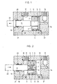
- the piston pump shown in the figures can be used for various liquids, such as water, milk, cream.
- the piston pump consists of a cylinder 1 and two end parts 14 and 16 screwed to the cylinder 1 by means of connecting screws 21.
- One 14 of the end parts is provided with an inlet 15 for the liquid.
- the piston 2 with the piston rod 11 is arranged to be reciprocable in the cylinder 1.
- the piston 2 is provided on its peripheral surface with annular seals 4.
- the piston 2 is further perforated parallel to its axis, as can be seen from FIG. 3.
- the number of holes 3 can advantageously be three.
- a circular piston cover 5 separate from the piston 2 is provided on the suction side of the piston 2.
- the diameter of the piston cover 5 does not exceed the diameter of the piston 2; it is advantageously a few millimeters smaller than that of the piston 2.
- the piston cover 5 has a neck 6 with an internal thread 7, which passes through a central bore 22 of the piston 2 with play.
- a pin 12 with an external thread 13 of the piston rod 11 is screwed into the neck 6 of the piston cover 5.
- the diameter of the piston rod 11 is larger than that of the pin 12 with an external thread 13 and that of the bore 22 in the piston 2.
- the outside of the neck is coated with Teflon 8 to prevent abrasion.
- connection of the piston cover 5 with the piston rod 11 can be adjusted as desired. This connection is such that the piston cover 5 during the return stroke of the piston 2 against the first End part 14 with inlet 15 is spaced from the piston 2. As a result, an intermediate space 24 for the flow of the liquid through the piston 2 is formed between the piston 2 and the piston cover 5.
- the distance between the piston cover 5 and the piston 2 is at most 2 mm and is given by the fact that the piston rod 11 is supported against the pressure side of the piston 2 and presses it during the return stroke.
- the piston cover 5 lies close to the piston 2, so that the holes 3 in the piston 2 are closed.
- the piston 2 is pulled through the piston rod 11, a gap being formed between the edge of the piston rod 11 facing the piston 2 and the pressure side of the piston 2.
- the liquid is pressed out of the working space of the cylinder 1 via the outlet 17.
- the liquid cannot escape along the inner wall of the cylinder 1 because the piston in the cylinder 1 is sealed by ring-shaped seals 4.
- the liquid can also not flow through the holes 3 in the piston 2 because they are sealed off by the piston cover 5.
- the piston 2 is provided with a raised edge 9 on its suction side.
- the edge of the piston cover is folded inwards on its side facing the piston 2.
- the folded edge 10 of the piston cover 5 comes to rest on the raised edge 9 of the piston 2, so that the piston 2 forms a tight fit with the piston cover 5.
- the outside diameter of the piston cover 5 is somewhat smaller than the outside diameter of the piston 2.
- the second end part 16 has a sealed bore 19 through which the piston rod 11 is passed.
- the piston rod 11 is then connected to a drive shaft 23 of an electric motor (not shown), advantageously eccentrically. With 18 and 20 seals are designated.
- Such a piston pump can, for. B. be used in a device for making whipped cream.
- the cream with air is fed into the pump through the inlet.
- the piston which is driven by an electric motor at 1,500 rpm, reciprocates, the stroke length varying in the range of approximately 10 mm.
- the cream with air sucked into the cylinders is forced out of the cylinder into a homogenizer, in which the blow occurs.
- the pressure in the piston pump is around 6.7 atm.
Landscapes
- Engineering & Computer Science (AREA)
- Mechanical Engineering (AREA)
- General Engineering & Computer Science (AREA)
- Reciprocating Pumps (AREA)
Priority Applications (1)
| Application Number | Priority Date | Filing Date | Title |
|---|---|---|---|
| AT83810165T ATE17158T1 (de) | 1982-04-21 | 1983-04-20 | Kolbenpumpe fuer fluessigkeiten. |
Applications Claiming Priority (2)
| Application Number | Priority Date | Filing Date | Title |
|---|---|---|---|
| CH242082 | 1982-04-21 | ||
| CH2420/82 | 1982-04-21 |
Publications (2)
| Publication Number | Publication Date |
|---|---|
| EP0093691A1 true EP0093691A1 (fr) | 1983-11-09 |
| EP0093691B1 EP0093691B1 (fr) | 1985-12-27 |
Family
ID=4233390
Family Applications (1)
| Application Number | Title | Priority Date | Filing Date |
|---|---|---|---|
| EP83810165A Expired EP0093691B1 (fr) | 1982-04-21 | 1983-04-20 | Pompe à piston pour liquides |
Country Status (3)
| Country | Link |
|---|---|
| EP (1) | EP0093691B1 (fr) |
| AT (1) | ATE17158T1 (fr) |
| DE (1) | DE3361613D1 (fr) |
Cited By (5)
| Publication number | Priority date | Publication date | Assignee | Title |
|---|---|---|---|---|
| US5035440A (en) * | 1989-08-09 | 1991-07-30 | Chappell International, Inc. | Pump |
| US5127804A (en) * | 1989-08-09 | 1992-07-07 | Innovative Bicycle Products, Inc. | Bicycle seat-tube pump with one-way valves |
| FR2689570A1 (fr) * | 1992-04-07 | 1993-10-08 | Serac Group | Pompe volumétrique. |
| EP0715039A1 (fr) | 1994-11-30 | 1996-06-05 | Fischer, Willibald | Elément de coffrage |
| FR2817848A1 (fr) * | 2000-12-12 | 2002-06-14 | Rexam Sofab | Micropompe electronique |
Citations (9)
| Publication number | Priority date | Publication date | Assignee | Title |
|---|---|---|---|---|
| FR489088A (fr) * | 1917-02-16 | 1918-12-13 | Georges Constantinesco | Perfectionnements aux pompes |
| DE462509C (de) * | 1926-03-10 | 1928-07-13 | John Coard Franke | Verfahren zum Heben von Fluessigkeiten mittels Pumpen mit Schoepfkolben |
| CH253083A (de) * | 1946-05-10 | 1948-02-15 | Maier Emilio | Mit Trägheitskraft arbeitende Kolbenpumpe. |
| US2933050A (en) * | 1957-05-23 | 1960-04-19 | Reynolds Oil Well Pumps Inc | Oil well pump |
| FR1323618A (fr) * | 1962-02-27 | 1963-04-12 | Perfectionnement aux pompes à piston | |
| FR1592548A (fr) * | 1968-06-21 | 1970-05-19 | ||
| US3536424A (en) * | 1968-11-12 | 1970-10-27 | Hydro Seal Ltd | Pump and piston assembly therefor |
| DE2263363A1 (de) * | 1972-12-23 | 1974-07-11 | Canada Tiefbohrgeraete Und Mas | Kolbenpumpe, insbesondere tiefpumpe |
| DE2628985A1 (de) * | 1976-06-28 | 1977-12-29 | Speck Kolbenpumpen Fabrik | Zylinder-kolbenanordnung fuer eine fluessigkeitspumpe |
-
1983
- 1983-04-20 AT AT83810165T patent/ATE17158T1/de not_active IP Right Cessation
- 1983-04-20 DE DE8383810165T patent/DE3361613D1/de not_active Expired
- 1983-04-20 EP EP83810165A patent/EP0093691B1/fr not_active Expired
Patent Citations (9)
| Publication number | Priority date | Publication date | Assignee | Title |
|---|---|---|---|---|
| FR489088A (fr) * | 1917-02-16 | 1918-12-13 | Georges Constantinesco | Perfectionnements aux pompes |
| DE462509C (de) * | 1926-03-10 | 1928-07-13 | John Coard Franke | Verfahren zum Heben von Fluessigkeiten mittels Pumpen mit Schoepfkolben |
| CH253083A (de) * | 1946-05-10 | 1948-02-15 | Maier Emilio | Mit Trägheitskraft arbeitende Kolbenpumpe. |
| US2933050A (en) * | 1957-05-23 | 1960-04-19 | Reynolds Oil Well Pumps Inc | Oil well pump |
| FR1323618A (fr) * | 1962-02-27 | 1963-04-12 | Perfectionnement aux pompes à piston | |
| FR1592548A (fr) * | 1968-06-21 | 1970-05-19 | ||
| US3536424A (en) * | 1968-11-12 | 1970-10-27 | Hydro Seal Ltd | Pump and piston assembly therefor |
| DE2263363A1 (de) * | 1972-12-23 | 1974-07-11 | Canada Tiefbohrgeraete Und Mas | Kolbenpumpe, insbesondere tiefpumpe |
| DE2628985A1 (de) * | 1976-06-28 | 1977-12-29 | Speck Kolbenpumpen Fabrik | Zylinder-kolbenanordnung fuer eine fluessigkeitspumpe |
Cited By (8)
| Publication number | Priority date | Publication date | Assignee | Title |
|---|---|---|---|---|
| US5035440A (en) * | 1989-08-09 | 1991-07-30 | Chappell International, Inc. | Pump |
| US5127804A (en) * | 1989-08-09 | 1992-07-07 | Innovative Bicycle Products, Inc. | Bicycle seat-tube pump with one-way valves |
| FR2689570A1 (fr) * | 1992-04-07 | 1993-10-08 | Serac Group | Pompe volumétrique. |
| EP0569262A1 (fr) * | 1992-04-07 | 1993-11-10 | Serac France | Pompe volumétrique |
| US5292236A (en) * | 1992-04-07 | 1994-03-08 | Serac France | Positive displacement pump with pivot piston valve |
| EP0715039A1 (fr) | 1994-11-30 | 1996-06-05 | Fischer, Willibald | Elément de coffrage |
| FR2817848A1 (fr) * | 2000-12-12 | 2002-06-14 | Rexam Sofab | Micropompe electronique |
| WO2002047826A1 (fr) * | 2000-12-12 | 2002-06-20 | Rexam Dispensing Systems | Micropompe electronique |
Also Published As
| Publication number | Publication date |
|---|---|
| EP0093691B1 (fr) | 1985-12-27 |
| ATE17158T1 (de) | 1986-01-15 |
| DE3361613D1 (en) | 1986-02-06 |
Similar Documents
| Publication | Publication Date | Title |
|---|---|---|
| DE2642642A1 (de) | Versorgungssystem zur versorgung einer spritzpistole mit farbe | |
| EP0216043B1 (fr) | Dispositif pour distribuer des matériaux liquides ou pâteux | |
| DE19921293A1 (de) | Ölzuleitungsvorrichtung für einen Linearkompressor | |
| DE2806788A1 (de) | Pumpe-duese fuer brennkraftmaschinen | |
| DE69508522T2 (de) | Hubkolbenpumpe mit Vorpumpe | |
| DE4436479A1 (de) | Luftventil mit Verbindungseinrichtung zum Verhindern von Vereisung | |
| EP0394383B1 (fr) | Pompe peristaltique | |
| EP0226070B1 (fr) | Dispositif de pompage pour débiter des quantités prédéterminées d'au moins deux composants | |
| DE3781770T2 (de) | Schnellen druck aufbauende tauchkolbenpumpe. | |
| DE2255773A1 (de) | Doppelt wirkende dosierpumpe | |
| EP0093691A1 (fr) | Pompe à piston pour liquides | |
| DE2852749A1 (de) | Foerderpumpe | |
| DE3526629A1 (de) | Verteilereinspritzpumpe fuer brennkraftmaschinen | |
| EP0007109A1 (fr) | Appareil pour le dosage d'une solution d'agents chimiques dans un courant de liquide | |
| DE1653577A1 (de) | Hydraulische Pumpe nach Art einer pulsierenden Membranpumpe | |
| DE2410766C3 (de) | Stellvorrichtung mit einem Axial- Stellmotor, insbesondere zur Betätigung von Gasheizungsventilen | |
| DE2134207C2 (de) | Füll- und Dosiergerät für zähflüssige und/oder fädenziehende Flüssigkeiten | |
| DE2711208A1 (de) | Verfahren und vorrichtung zum dosieren und abfuellen insbesondere hochviskoser medien | |
| EP0441100A1 (fr) | Dispositif pour commander la soupape d'échappement d'un moteur à combustion interne à piston | |
| DE912560C (de) | Vorrichtung zum Zerstaeuben von Fluessigkeiten mit Zerstaeuberduese und elektrisch angetriebener Kolbenpumpe | |
| DE2448893C2 (de) | Elektrisches Sprühgerät | |
| DE3910992C2 (fr) | ||
| DE942066C (de) | Kolbenpumpe | |
| DE2652567A1 (de) | Verduennungsvorrichtung | |
| EP0280745A1 (fr) | Pompe à membrane à piston |
Legal Events
| Date | Code | Title | Description |
|---|---|---|---|
| PUAI | Public reference made under article 153(3) epc to a published international application that has entered the european phase |
Free format text: ORIGINAL CODE: 0009012 |
|
| AK | Designated contracting states |
Designated state(s): AT BE CH DE FR GB IT LI LU NL SE |
|
| 17P | Request for examination filed |
Effective date: 19831105 |
|
| GRAA | (expected) grant |
Free format text: ORIGINAL CODE: 0009210 |
|
| AK | Designated contracting states |
Designated state(s): AT BE CH DE FR GB IT LI LU NL SE |
|
| PG25 | Lapsed in a contracting state [announced via postgrant information from national office to epo] |
Ref country code: NL Effective date: 19851227 Ref country code: IT Free format text: LAPSE BECAUSE OF FAILURE TO SUBMIT A TRANSLATION OF THE DESCRIPTION OR TO PAY THE FEE WITHIN THE PRESCRIBED TIME-LIMIT;WARNING: LAPSES OF ITALIAN PATENTS WITH EFFECTIVE DATE BEFORE 2007 MAY HAVE OCCURRED AT ANY TIME BEFORE 2007. THE CORRECT EFFECTIVE DATE MAY BE DIFFERENT FROM THE ONE RECORDED. Effective date: 19851227 Ref country code: BE Effective date: 19851227 |
|
| REF | Corresponds to: |
Ref document number: 17158 Country of ref document: AT Date of ref document: 19860115 Kind code of ref document: T |
|
| PG25 | Lapsed in a contracting state [announced via postgrant information from national office to epo] |
Ref country code: SE Effective date: 19860131 |
|
| REF | Corresponds to: |
Ref document number: 3361613 Country of ref document: DE Date of ref document: 19860206 |
|
| PG25 | Lapsed in a contracting state [announced via postgrant information from national office to epo] |
Ref country code: AT Effective date: 19860420 |
|
| PG25 | Lapsed in a contracting state [announced via postgrant information from national office to epo] |
Ref country code: LU Free format text: LAPSE BECAUSE OF NON-PAYMENT OF DUE FEES Effective date: 19860430 |
|
| ET | Fr: translation filed | ||
| NLV1 | Nl: lapsed or annulled due to failure to fulfill the requirements of art. 29p and 29m of the patents act | ||
| PLBE | No opposition filed within time limit |
Free format text: ORIGINAL CODE: 0009261 |
|
| STAA | Information on the status of an ep patent application or granted ep patent |
Free format text: STATUS: NO OPPOSITION FILED WITHIN TIME LIMIT |
|
| 26N | No opposition filed | ||
| GBPC | Gb: european patent ceased through non-payment of renewal fee | ||
| PG25 | Lapsed in a contracting state [announced via postgrant information from national office to epo] |
Ref country code: GB Effective date: 19881122 |
|
| PGFP | Annual fee paid to national office [announced via postgrant information from national office to epo] |
Ref country code: FR Payment date: 19890308 Year of fee payment: 7 |
|
| PGFP | Annual fee paid to national office [announced via postgrant information from national office to epo] |
Ref country code: DE Payment date: 19890331 Year of fee payment: 7 |
|
| PG25 | Lapsed in a contracting state [announced via postgrant information from national office to epo] |
Ref country code: FR Effective date: 19901228 |
|
| PG25 | Lapsed in a contracting state [announced via postgrant information from national office to epo] |
Ref country code: DE Effective date: 19910101 |
|
| REG | Reference to a national code |
Ref country code: FR Ref legal event code: ST |
|
| PGFP | Annual fee paid to national office [announced via postgrant information from national office to epo] |
Ref country code: CH Payment date: 19970428 Year of fee payment: 15 |
|
| PG25 | Lapsed in a contracting state [announced via postgrant information from national office to epo] |
Ref country code: LI Free format text: LAPSE BECAUSE OF NON-PAYMENT OF DUE FEES Effective date: 19980430 Ref country code: CH Free format text: LAPSE BECAUSE OF NON-PAYMENT OF DUE FEES Effective date: 19980430 |
|
| REG | Reference to a national code |
Ref country code: CH Ref legal event code: PL |