EP0093980A1 - Circuit d'alimentation en courant électrique pour l'entraînement d'un moteur - Google Patents
Circuit d'alimentation en courant électrique pour l'entraînement d'un moteur Download PDFInfo
- Publication number
- EP0093980A1 EP0093980A1 EP83104229A EP83104229A EP0093980A1 EP 0093980 A1 EP0093980 A1 EP 0093980A1 EP 83104229 A EP83104229 A EP 83104229A EP 83104229 A EP83104229 A EP 83104229A EP 0093980 A1 EP0093980 A1 EP 0093980A1
- Authority
- EP
- European Patent Office
- Prior art keywords
- transistor
- circuit
- power supply
- voltage
- base
- Prior art date
- Legal status (The legal status is an assumption and is not a legal conclusion. Google has not performed a legal analysis and makes no representation as to the accuracy of the status listed.)
- Ceased
Links
- 238000004804 winding Methods 0.000 description 15
- 239000003990 capacitor Substances 0.000 description 11
- 238000010586 diagram Methods 0.000 description 7
- 230000007935 neutral effect Effects 0.000 description 6
- 238000010276 construction Methods 0.000 description 2
- 238000009499 grossing Methods 0.000 description 2
- 230000004048 modification Effects 0.000 description 2
- 238000012986 modification Methods 0.000 description 2
- 238000013021 overheating Methods 0.000 description 1
Images



Classifications
-
- H—ELECTRICITY
- H02—GENERATION; CONVERSION OR DISTRIBUTION OF ELECTRIC POWER
- H02P—CONTROL OR REGULATION OF ELECTRIC MOTORS, ELECTRIC GENERATORS OR DYNAMO-ELECTRIC CONVERTERS; CONTROLLING TRANSFORMERS, REACTORS OR CHOKE COILS
- H02P7/00—Arrangements for regulating or controlling the speed or torque of electric DC motors
- H02P7/06—Arrangements for regulating or controlling the speed or torque of electric DC motors for regulating or controlling an individual DC dynamo-electric motor by varying field or armature current
- H02P7/18—Arrangements for regulating or controlling the speed or torque of electric DC motors for regulating or controlling an individual DC dynamo-electric motor by varying field or armature current by master control with auxiliary power
- H02P7/24—Arrangements for regulating or controlling the speed or torque of electric DC motors for regulating or controlling an individual DC dynamo-electric motor by varying field or armature current by master control with auxiliary power using discharge tubes or semiconductor devices
- H02P7/28—Arrangements for regulating or controlling the speed or torque of electric DC motors for regulating or controlling an individual DC dynamo-electric motor by varying field or armature current by master control with auxiliary power using discharge tubes or semiconductor devices using semiconductor devices
-
- H—ELECTRICITY
- H02—GENERATION; CONVERSION OR DISTRIBUTION OF ELECTRIC POWER
- H02M—APPARATUS FOR CONVERSION BETWEEN AC AND AC, BETWEEN AC AND DC, OR BETWEEN DC AND DC, AND FOR USE WITH MAINS OR SIMILAR POWER SUPPLY SYSTEMS; CONVERSION OF DC OR AC INPUT POWER INTO SURGE OUTPUT POWER; CONTROL OR REGULATION THEREOF
- H02M3/00—Conversion of DC power input into DC power output
- H02M3/22—Conversion of DC power input into DC power output with intermediate conversion into AC
- H02M3/24—Conversion of DC power input into DC power output with intermediate conversion into AC by static converters
- H02M3/28—Conversion of DC power input into DC power output with intermediate conversion into AC by static converters using discharge tubes with control electrode or semiconductor devices with control electrode to produce the intermediate AC
- H02M3/325—Conversion of DC power input into DC power output with intermediate conversion into AC by static converters using discharge tubes with control electrode or semiconductor devices with control electrode to produce the intermediate AC using devices of a triode or a transistor type requiring continuous application of a control signal
- H02M3/335—Conversion of DC power input into DC power output with intermediate conversion into AC by static converters using discharge tubes with control electrode or semiconductor devices with control electrode to produce the intermediate AC using devices of a triode or a transistor type requiring continuous application of a control signal using semiconductor devices only
- H02M3/338—Conversion of DC power input into DC power output with intermediate conversion into AC by static converters using discharge tubes with control electrode or semiconductor devices with control electrode to produce the intermediate AC using devices of a triode or a transistor type requiring continuous application of a control signal using semiconductor devices only in a self-oscillating arrangement
- H02M3/3382—Conversion of DC power input into DC power output with intermediate conversion into AC by static converters using discharge tubes with control electrode or semiconductor devices with control electrode to produce the intermediate AC using devices of a triode or a transistor type requiring continuous application of a control signal using semiconductor devices only in a self-oscillating arrangement in a push-pull circuit arrangement
-
- H—ELECTRICITY
- H02—GENERATION; CONVERSION OR DISTRIBUTION OF ELECTRIC POWER
- H02P—CONTROL OR REGULATION OF ELECTRIC MOTORS, ELECTRIC GENERATORS OR DYNAMO-ELECTRIC CONVERTERS; CONTROLLING TRANSFORMERS, REACTORS OR CHOKE COILS
- H02P7/00—Arrangements for regulating or controlling the speed or torque of electric DC motors
- H02P7/06—Arrangements for regulating or controlling the speed or torque of electric DC motors for regulating or controlling an individual DC dynamo-electric motor by varying field or armature current
- H02P7/18—Arrangements for regulating or controlling the speed or torque of electric DC motors for regulating or controlling an individual DC dynamo-electric motor by varying field or armature current by master control with auxiliary power
- H02P7/24—Arrangements for regulating or controlling the speed or torque of electric DC motors for regulating or controlling an individual DC dynamo-electric motor by varying field or armature current by master control with auxiliary power using discharge tubes or semiconductor devices
- H02P7/28—Arrangements for regulating or controlling the speed or torque of electric DC motors for regulating or controlling an individual DC dynamo-electric motor by varying field or armature current by master control with auxiliary power using discharge tubes or semiconductor devices using semiconductor devices
- H02P7/285—Arrangements for regulating or controlling the speed or torque of electric DC motors for regulating or controlling an individual DC dynamo-electric motor by varying field or armature current by master control with auxiliary power using discharge tubes or semiconductor devices using semiconductor devices controlling armature supply only
Definitions
- This invention relates to a power supply circuit for driving a motor, which can be connected to AC power sources providing different source voltages.
- Fig. 1 shows a prior art power supply circuit for a motor driver of the type mentioned. It includes a full-wave rectifier circuit 2 for rectifying an AC voltage from an AC power source PS, capacitors Cl and C2 connected in series between the output terminals of the full-wave rectifier circuit 2, a switch SW1 connected between the connection point between the capacitors Cl and C2 and one of the input terminals of the full-wave rectifier circuit 2, and a half-bridge type DC-DC converter 4 for stepping down the DC voltage between the output terminals of the full-wave rectifier circuit 2.
- a chargeable battery E is connected between the output terminals of the converter 4, and also a motor 6 as a load is connected in series with a switch SW2 between these output terminals.
- the half-bridge type DC-DC converter 4 has a well-known construction including npn transistors TR1 and TR2, primary and secondary windings Ll and L2 inductively coupled, feedback windings FL1 and FL2 inductively coupled with the primary winding Ll, and diodes Dl and D2.
- the npn transistors TR1 and TR2 have their current paths connected in series between the output terminals of the full-wave rectifier circuit 2.
- the primary winding Ll has one terminal connected to the connection point between the npn transistors TR1 and TR2 and the other terminal connected to the connection point between the capacitors Cl and C2.
- the feedbak windings FL1 and FL2 are respectively connected between the bases and emitters of the respective transistors TR1 and TR2.
- the diodes Dl and D2 have their anodes connected to the respective opposite ends of the secondary winding L2 and their cathodes connected together.
- the output voltage of the converter 4 appears between the connection point of the diodes Dl and D2 and a neutral point NP of the secondary winding L2.
- a DC voltage Vl obtained from the full-wave rectifier circuit 2 appears between the output terminals of the series capacitor circuit of the capacitors Cl and C2 when the switch SW1 is in the OFF position.
- the DC-DC converter 4 generates a voltage equal to 1/n (n bing the turn ratio between the primary and secondary windings Ll and L2) times the DC voltage Vl.
- the half-wave rectifier circuit 2 functions as a voltage doubler rectifier.
- a DC voltage V2 is supplied to the converter 4, and the converter 4 generates a DC voltage V2/n.
- the switch SW1 may be set ON when the motor power supply circuit shown in Fig. 1 is connected to, for instance, a 100-V AC power source, while it may be set OFF when the power supply circuit is connected to a 200-V AC power source.
- a substantially equal effective voltage is applied to the DC-DC converter 4 when the 100-V AC power source is connected to the power supply circuit and when the 200-V AC power source is connected.
- the battery E or motor 6 can thus be supplied with a predetermined voltage.
- the motor power supply circuit can be connected to two different AC power sources. However, it is necessary that the ratio of the effective output voltages in these two cases be 2 : 1. That is, it cannot be adapted for use with 100-V and 150-V AC voltage, for instance.
- the switch SIV1 has to be operated according to the AC power source that is used with the power supply circuit. If the switch SW1 is operated erroneously, the motor 6 may fail to be driven or may be damaged.
- An object of the present invention is to provide a power supply circuit which is operable with different AC source voltages to drive a motor stably and reliably.
- a power supply circuit which comprises a rectifier circuit for rectifying an AC source voltage, a converter circuit for stepping down a DC voltage from the rectifier circuit, and a regulator circuit operated by the DC voltage of the converter circuit to supply a constant voltage or current to a motor to be driven.
- the regulator circuit which is operated by the DC voltage of the comparator circuit supplies a constant voltage or current to the motor even when different AC source voltages are used.
- the motor can thus be driven stably and reliably at all times.
- the DC-DC converter 4 has the same construction as that shown in Fig. 1, including npn transistors TR1 and TR2, primary and secondary windings Ll and L2, feedback windings FL1 and FL2 and diodes Dl and D2.
- the constant voltage circuit 8 includes an npn transistor TR3, a resistor Rl and three diodes D3 to D5.
- the collector of the npn transistor TR3 is connected to the high- potential output terminals of the DC-DC converter 4, i.e., the cathode of each of the diodes Dl and D2.
- the resistor Rl is connected between the base and collector of the transistor TR3.
- the diodes D3 to D5 are connected in series and in a forward-bias direction between the base of the transistor TR3 and the low-potential output terminal of the DC-DC converter 4, i.e., the neutral point NP of the secondary winding L2.
- the AC voltage from the AC power source PS is rectified by the full-wave rectifier circuit 2, smoothed by the smoothing capacitor C3 and then stepped down by the DC-DC converter 4.
- the constant voltage circuit 8 is operated by the output voltage of the DC-DC converter 4 to generate a constant voltage between its output terminals, i.e., between the emitter of the transistor TR3 and the cathode of the diode D5.
- the switch SW2 is in the OFF position, the battery E is charged by the constant voltage applied to it.
- the switch SW2 is in the ON position, the constant voltage from the constant voltage circuit 8 is applied to the motor 6 to drive the motor 6 stably and reliably.
- the switch SW2 is turned on with the power source disconnected, the motor 6 is driven by the battery E.
- the voltage VE3 is substantially constant, as is apparent from the equation (2).
- a change in the voltage VC3 causes a correcponding change in the voltage VCE to hold the voltage VE3 constant, as can be seen from the equation (1).
- the output voltage VC3 of the DC-DC converter 4 is also doubled. In this case, however, an increase of the voltage VC3 increases the collector-emitter voltage VCE of the transistor TR3 to hold the emitter voltage VE3 constant. It should be appreciated that the constant voltage circuit 8 provides a substantially constant output voltage irrespective of a change in the AC power source voltage supplied to the rectifier circuit 2. It is thus possible to reliably charge the battery E and also to drive the motor 6 stably and reliably.
- the ratio between a current flowing through the collector of the transistor TR3 when the switch SW2 is in the ON position and that obtained when the switch is in the OFF position is 10 : 1
- the ratio of power consumption of the transistor TR3 in the former and latter cases is also 10 : 1.
- the power consumption of the transistor TR3 is low, and the battery E can be charged for a long period of time with the switch SW2 set in the OFF position without any possibility of damaging the transistor TR3 due to overheating.
- the output voltage of the constant voltage circuit 8 may be set to be sufficiently low so that a small size motor can be used as the motor 6.
- Fig. 3 shows a modification of the power supply circuit shown in Fig. 2.
- This circuit uses a Darlington circuit including npn transistors TR4 and TR5 in lieu of the transistor TR3 in the circuit of Fig. 2. The remainder of the circuit is the same as that of Fig. 2.
- the transistors TR4 and TR5 have their collectors connected together.
- the collector and base of the transistor TR5 are connected to the opposite terminals of the resistor Rl respectively.
- the emitter of the transistor TR5 is connected to the base of the transistor TR4.
- the emitter voltage VE4 on the transistor TR4 is given as where VB4 is the base voltage of the transistor TR4. It will be seen that the motor 6 can be driven with a lower voltage than in the case of the power supply circuit of Fig. 2. In addition, a larger drive current can be supplied to the motor 6 owing to the Darlington circuit, so that the stability of the motor 6 can be enhanced.
- Fig. 4 shows a different embodiment of the power supply circuit according to the invention.
- This circuit uses diodes D3 and D4 which are connected with the opposite polarity to that of the diodes Dl and D2 noted before and also uses a constant voltage circuit 10 instead of the constant voltage circuit 8 noted before.
- the rest of the circuit is the same as the circuit shown in Fig. 2.
- the constant voltage circuit 10 includes an npn transistor TR6, resistors R2 and R3, a pnp transistor TR7 and an npn transistor TR8.
- the emitter of the transistor TR6 is connected to the low potential output terminal of the DC-DC converter 4, i.e., the anode of each of the diodes D3 and D4.
- the resistors R2 and R3 are connected in series between the collector of the transistor TR6 and the high potential output terminal of the comparator 4, i.e., the neutral point NP of the secondary winding L2.
- the transistor TR7 has the collector connected to the base of the transistor TR6, the emitter connected through the resistor R4 to the neutral point NP of the secondary winding L2 and the base connected through the resistor Rl to the anode of each of the diodes D3 and D4.
- the transistor TR8 has the emitter connected to the base of the transistor TR7, the collector connected to the neutral point NP of the secondary winding L2 and the base connected to the connection point between the resistors Rl and R2.
- a change in the output voltage of the constant voltage circuit 10 causes a corresponding change in the output voltage of the voltage divider of the resistors R2 and R3 to control the conduction resistance of the transistor TR8.
- a base voltage of the transistor TR7 is changed so as to change the base current into the transistor TR6 through the resistor R4 and transistor TR7.
- the collector-emitter voltage VCE of the transistor TR6 is thus changed to keep the collector voltage VC6 of the transistor TR6 at a predetermined voltage.
- the collector voltage VC6 When, for example, the collector voltage VC6 is increased, the potential on the connection point between the resistors R2 and R3 is increased to reduce the conduction resistance of the transistor TR8. As a result, the base potential on the transistor TR7 is increased to reduce the base current flowing through the resistor R4 and transistor TR7 into the base of the transistor TR6. The base-emitter voltage VCE on the transistor TR6 is thus increased to reduce the collector voltage VC6 to a predetermined value.
- the emitter voltage VE6 of the transistor TR6 is given as follows:
- the transistor TR6 may be operated in the saturation mode. In this case, a relation of VBE > VCE can be obtained.
- the power supply circuit of Fig. 4 it is possible to reduce the output voltage of the converter 4, i.e., reduce the number of turns of the secondary winding L2, compared to the power supply circuit of Fig. 2 or 3. By so doing, changes in the output voltage of the converter 4 with fluctuations of the power source voltage can be reduced to minimize the power loss in the transistor TR6.
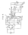
- Fig. 5 shows a power supply circuit according to another embodiment of this invention.
- This circuit uses a constant current circuit 12 in lieu of the constant voltage circuit 10.
- the remainder of the circuit is the same as the circuit of Fig. 4.
- the constant current circuit 12 includes transistors TR6 and TR7, a pnp transistor TR9 and resistors Rl, R4 and R5.
- the pnp transistor TR9 has its emitter connected to the neutral point NP and its base connected through the resistor R5 to its emitter.
- the resistor R6 is connected between the emitter of the transistor TR9 and the switch SW2.
- Fig. 6 shows another power supply circuit, which includes a voltage and current regulator circuit 14 having the functions of the constant voltage circuit 10 in Fig. 4 and the constant current circuit 12 in Fig. 5.
- the regulator circuit 14 includes a resistors Rl to R4 and transistors TR6 to TR8 connected in the same manner as in the constant voltage circuit 10 of Fig. 4 and resistors R5 and R6 and a transistor TR9 connected in the same manner as in the constant current circuit 12 of Fig. 5.
- this power supply circuit it is possible to prevent an excessive charging current from being supplied to the battery E in the discharged state and the life of the battery E from being shortened. It is also possible to prevent an excessive operation current from being supplied to the motor with a heavy load, and the life of the motor 6 from being shortened. Since, with this power supply circuit, the operation of current regulation is effected while an operating current larger than a minimum operation current is supplied to the motor 6, the motor 6 will not be stopped even when a heavy load is applied to it.
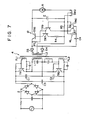
- Fig. 7 shows another power supply circuit which includes a trigger control circuit 16 connected to a constant current circuit 12. The remainder of the circuit is the same as the circuit of Fig. 5.
- the trigger control circuit 16 includes a pnp transistor TRIO and a resistor R7.
- the transistor TRIO has the emitter-collector path connected in parallel with the resistor R6 and the base connected through the capacitor C4 to the anode of each of the diodes D3 and D4.
- the resistor R7 is connected between the emitter and base of the transistor TRIO.
- the base current into the transistor TRIO is interrupted to turn off the transistor TRIO.
- the emitter and base of the transistor TR9 are thus coupled together through a parallel resistor circuit of the resistors R5 and R6. Now the transistor TR9 executes the current detecting operation, and a constant current is supplied from the constant current circuit 12 to the motor 6.
- the transistors TR3 to TR6 may be replaced by pnp transistors.
Landscapes
- Engineering & Computer Science (AREA)
- Power Engineering (AREA)
- Dc-Dc Converters (AREA)
- Continuous-Control Power Sources That Use Transistors (AREA)
- Dry Shavers And Clippers (AREA)
- Control Of Direct Current Motors (AREA)
Applications Claiming Priority (2)
| Application Number | Priority Date | Filing Date | Title |
|---|---|---|---|
| JP72695/82 | 1982-04-30 | ||
| JP57072695A JPS58192491A (ja) | 1982-04-30 | 1982-04-30 | 電気シエ−バ− |
Publications (1)
| Publication Number | Publication Date |
|---|---|
| EP0093980A1 true EP0093980A1 (fr) | 1983-11-16 |
Family
ID=13496756
Family Applications (1)
| Application Number | Title | Priority Date | Filing Date |
|---|---|---|---|
| EP83104229A Ceased EP0093980A1 (fr) | 1982-04-30 | 1983-04-29 | Circuit d'alimentation en courant électrique pour l'entraînement d'un moteur |
Country Status (3)
| Country | Link |
|---|---|
| US (1) | US4570211A (fr) |
| EP (1) | EP0093980A1 (fr) |
| JP (1) | JPS58192491A (fr) |
Families Citing this family (10)
| Publication number | Priority date | Publication date | Assignee | Title |
|---|---|---|---|---|
| JP2857149B2 (ja) * | 1987-04-17 | 1999-02-10 | 本田技研工業株式会社 | 車載エンジン点火装置 |
| US4864488A (en) * | 1988-06-27 | 1989-09-05 | Ncr Corporation | Single level D.C. output voltage power supply |
| JP2711599B2 (ja) * | 1991-07-25 | 1998-02-10 | 株式会社ニフレックス | コアドリル自動送り装置 |
| GB2265774B (en) * | 1992-03-30 | 1996-06-12 | Yang Tai Her | Stepped compound voltage power supply and field control arrangement for a DC motor driving circuit |
| US5715155A (en) * | 1996-10-28 | 1998-02-03 | Norax Canada Inc. | Resonant switching power supply circuit |
| US6215683B1 (en) * | 1998-10-13 | 2001-04-10 | Lucent Technologies Inc. | Power converter with voltage dependent switchable modes |
| DE102005023291A1 (de) * | 2005-05-20 | 2006-11-23 | Sma Technologie Ag | Wechselrichter |
| US20090085543A1 (en) * | 2007-09-28 | 2009-04-02 | Astec International Limited | Variable Output Voltage Power Converter |
| US20130271102A1 (en) * | 2012-04-12 | 2013-10-17 | Roger Lin | Power supply control structure |
| CN103560675B (zh) * | 2013-10-21 | 2017-01-04 | 广州金升阳科技有限公司 | 一种电源输出控制电路及多层电源供电系统 |
Citations (5)
| Publication number | Priority date | Publication date | Assignee | Title |
|---|---|---|---|---|
| US3337787A (en) * | 1964-09-24 | 1967-08-22 | Walter F Joseph | Direct current power supply having plural regulated outputs |
| DE2809313A1 (de) * | 1977-03-04 | 1978-09-14 | Sanyo Electric Co | Netzanschlussgeraet |
| GB2029989A (en) * | 1978-09-11 | 1980-03-26 | Philips Nv | Automatic control converters |
| EP0030026A1 (fr) * | 1979-11-29 | 1981-06-10 | Klaus Becker | Agencement de circuit pour l'alimentation stabilisée d'un utilisateur |
| DE2932061B2 (de) * | 1979-08-07 | 1981-06-11 | Siemens AG, 1000 Berlin und 8000 München | Schaltungsanordnung zur Erzeugung einer sicheren Ausgangsgleichspannung |
Family Cites Families (8)
| Publication number | Priority date | Publication date | Assignee | Title |
|---|---|---|---|---|
| GB766378A (en) * | 1954-08-11 | 1957-01-23 | Mullard Radio Valve Co Ltd | Improvements in or relating to voltage stabilising circuits |
| US3022457A (en) * | 1960-02-19 | 1962-02-20 | Texas Instruments Inc | Transistor voltage regulator |
| US3207973A (en) * | 1961-06-23 | 1965-09-21 | Gail D Smith | D.c. regulated power supply employing means for adjusting the input in response to output voltages variations |
| US3652919A (en) * | 1971-03-30 | 1972-03-28 | Bell Telephone Labor Inc | Base reach-through active series voltage regulator |
| US4088937A (en) * | 1974-06-07 | 1978-05-09 | Mitsubishi Denki Kabushiki Kaisha | Control apparatus |
| US4004209A (en) * | 1975-04-21 | 1977-01-18 | Xerox Corporation | Wide range power conversion system |
| JPS5241854A (en) * | 1975-09-29 | 1977-03-31 | Yokogawa Hokushin Electric Corp | Power circuit |
| JPS55122476A (en) * | 1979-03-14 | 1980-09-20 | Micron Kiki Kk | Dc-dc converter |
-
1982
- 1982-04-30 JP JP57072695A patent/JPS58192491A/ja active Pending
-
1983
- 1983-04-22 US US06/487,521 patent/US4570211A/en not_active Expired - Fee Related
- 1983-04-29 EP EP83104229A patent/EP0093980A1/fr not_active Ceased
Patent Citations (5)
| Publication number | Priority date | Publication date | Assignee | Title |
|---|---|---|---|---|
| US3337787A (en) * | 1964-09-24 | 1967-08-22 | Walter F Joseph | Direct current power supply having plural regulated outputs |
| DE2809313A1 (de) * | 1977-03-04 | 1978-09-14 | Sanyo Electric Co | Netzanschlussgeraet |
| GB2029989A (en) * | 1978-09-11 | 1980-03-26 | Philips Nv | Automatic control converters |
| DE2932061B2 (de) * | 1979-08-07 | 1981-06-11 | Siemens AG, 1000 Berlin und 8000 München | Schaltungsanordnung zur Erzeugung einer sicheren Ausgangsgleichspannung |
| EP0030026A1 (fr) * | 1979-11-29 | 1981-06-10 | Klaus Becker | Agencement de circuit pour l'alimentation stabilisée d'un utilisateur |
Non-Patent Citations (1)
| Title |
|---|
| LABORATORY PRACTICE, vol. 24, no. 9, September 1975 D. GOODMAN "Electronic speed control circuit for small D.C. motors", page 589 * |
Also Published As
| Publication number | Publication date |
|---|---|
| US4570211A (en) | 1986-02-11 |
| JPS58192491A (ja) | 1983-11-09 |
Similar Documents
| Publication | Publication Date | Title |
|---|---|---|
| US4246634A (en) | Start-up circuit for switch mode power supply | |
| JP3369134B2 (ja) | Dc−dcコンバータ | |
| US4570211A (en) | Power supply circuit for driving a motor | |
| JPH0527346B2 (fr) | ||
| JP2730787B2 (ja) | 電源回路 | |
| JPH0546788B2 (fr) | ||
| US4429356A (en) | Transistor inverter device | |
| JPH0680385U (ja) | スイッチング電源装置 | |
| US5515256A (en) | Self exciting type switching power supply circuit | |
| US5406469A (en) | Electronic switching power supply | |
| EP0835547B1 (fr) | Alimentation en mode commute dotee d'une capacite de compensation d'une tension d'entree variable | |
| EP0061730A2 (fr) | Dispositif d'onduleur à transistor | |
| JPH11136939A (ja) | スイッチング電源 | |
| US5838553A (en) | Voltage stabilized self-oscillating power supply | |
| KR930005928Y1 (ko) | 스위칭 트랜지스터의 베이스 구동회로 | |
| JP3458363B2 (ja) | スイッチング電源 | |
| JP4458572B2 (ja) | 電源装置 | |
| JP2533115Y2 (ja) | 電源装置 | |
| JPH043553Y2 (fr) | ||
| JPS6145697Y2 (fr) | ||
| JPS5910948Y2 (ja) | 電源装置 | |
| JPS635434Y2 (fr) | ||
| JPH0756632Y2 (ja) | 自励型dc−dcコンバータ | |
| JP2001327096A (ja) | リチウムイオン電池の充電制御回路 | |
| JP2501897Y2 (ja) | スイッチング電源 |
Legal Events
| Date | Code | Title | Description |
|---|---|---|---|
| PUAI | Public reference made under article 153(3) epc to a published international application that has entered the european phase |
Free format text: ORIGINAL CODE: 0009012 |
|
| 17P | Request for examination filed |
Effective date: 19830429 |
|
| AK | Designated contracting states |
Designated state(s): DE FR GB NL |
|
| STAA | Information on the status of an ep patent application or granted ep patent |
Free format text: STATUS: THE APPLICATION HAS BEEN REFUSED |
|
| 18R | Application refused |
Effective date: 19870712 |
|
| RIN1 | Information on inventor provided before grant (corrected) |
Inventor name: MANDA, YASUTAKE Inventor name: MIYABAYASHI, TADAO Inventor name: FUKUMOTO, SAKUO |