EP0094221B1 - Dossier réglable pour sièges - Google Patents
Dossier réglable pour sièges Download PDFInfo
- Publication number
- EP0094221B1 EP0094221B1 EP83302571A EP83302571A EP0094221B1 EP 0094221 B1 EP0094221 B1 EP 0094221B1 EP 83302571 A EP83302571 A EP 83302571A EP 83302571 A EP83302571 A EP 83302571A EP 0094221 B1 EP0094221 B1 EP 0094221B1
- Authority
- EP
- European Patent Office
- Prior art keywords
- chair
- gear wheel
- pawl
- spindle
- adjustment mechanism
- Prior art date
- Legal status (The legal status is an assumption and is not a legal conclusion. Google has not performed a legal analysis and makes no representation as to the accuracy of the status listed.)
- Expired
Links
- 230000000717 retained effect Effects 0.000 claims description 6
- 230000002093 peripheral effect Effects 0.000 claims description 3
- 230000013011 mating Effects 0.000 description 5
- 239000000463 material Substances 0.000 description 2
- 230000007935 neutral effect Effects 0.000 description 2
- 229920003002 synthetic resin Polymers 0.000 description 2
- 239000000057 synthetic resin Substances 0.000 description 2
- 238000010276 construction Methods 0.000 description 1
- 238000004519 manufacturing process Methods 0.000 description 1
- 239000002184 metal Substances 0.000 description 1
- 230000003014 reinforcing effect Effects 0.000 description 1
- 230000002441 reversible effect Effects 0.000 description 1
- 238000003466 welding Methods 0.000 description 1
Images


Classifications
-
- A—HUMAN NECESSITIES
- A47—FURNITURE; DOMESTIC ARTICLES OR APPLIANCES; COFFEE MILLS; SPICE MILLS; SUCTION CLEANERS IN GENERAL
- A47C—CHAIRS; SOFAS; BEDS
- A47C1/00—Chairs adapted for special purposes
- A47C1/02—Reclining or easy chairs
- A47C1/031—Reclining or easy chairs having coupled concurrently adjustable supporting parts
- A47C1/032—Reclining or easy chairs having coupled concurrently adjustable supporting parts the parts being movably-coupled seat and back-rest
- A47C1/03205—Reclining or easy chairs having coupled concurrently adjustable supporting parts the parts being movably-coupled seat and back-rest having adjustable and lockable inclination
- A47C1/03222—Reclining or easy chairs having coupled concurrently adjustable supporting parts the parts being movably-coupled seat and back-rest having adjustable and lockable inclination by means of screw-and-nut mechanism
-
- A—HUMAN NECESSITIES
- A47—FURNITURE; DOMESTIC ARTICLES OR APPLIANCES; COFFEE MILLS; SPICE MILLS; SUCTION CLEANERS IN GENERAL
- A47C—CHAIRS; SOFAS; BEDS
- A47C1/00—Chairs adapted for special purposes
- A47C1/02—Reclining or easy chairs
- A47C1/031—Reclining or easy chairs having coupled concurrently adjustable supporting parts
- A47C1/032—Reclining or easy chairs having coupled concurrently adjustable supporting parts the parts being movably-coupled seat and back-rest
- A47C1/03255—Reclining or easy chairs having coupled concurrently adjustable supporting parts the parts being movably-coupled seat and back-rest with a central column, e.g. rocking office chairs
-
- A—HUMAN NECESSITIES
- A47—FURNITURE; DOMESTIC ARTICLES OR APPLIANCES; COFFEE MILLS; SPICE MILLS; SUCTION CLEANERS IN GENERAL
- A47C—CHAIRS; SOFAS; BEDS
- A47C1/00—Chairs adapted for special purposes
- A47C1/02—Reclining or easy chairs
- A47C1/031—Reclining or easy chairs having coupled concurrently adjustable supporting parts
- A47C1/032—Reclining or easy chairs having coupled concurrently adjustable supporting parts the parts being movably-coupled seat and back-rest
- A47C1/03261—Reclining or easy chairs having coupled concurrently adjustable supporting parts the parts being movably-coupled seat and back-rest characterised by elastic means
- A47C1/03266—Reclining or easy chairs having coupled concurrently adjustable supporting parts the parts being movably-coupled seat and back-rest characterised by elastic means with adjustable elasticity
-
- A—HUMAN NECESSITIES
- A47—FURNITURE; DOMESTIC ARTICLES OR APPLIANCES; COFFEE MILLS; SPICE MILLS; SUCTION CLEANERS IN GENERAL
- A47C—CHAIRS; SOFAS; BEDS
- A47C1/00—Chairs adapted for special purposes
- A47C1/02—Reclining or easy chairs
- A47C1/031—Reclining or easy chairs having coupled concurrently adjustable supporting parts
- A47C1/032—Reclining or easy chairs having coupled concurrently adjustable supporting parts the parts being movably-coupled seat and back-rest
- A47C1/03261—Reclining or easy chairs having coupled concurrently adjustable supporting parts the parts being movably-coupled seat and back-rest characterised by elastic means
- A47C1/03272—Reclining or easy chairs having coupled concurrently adjustable supporting parts the parts being movably-coupled seat and back-rest characterised by elastic means with coil springs
- A47C1/03274—Reclining or easy chairs having coupled concurrently adjustable supporting parts the parts being movably-coupled seat and back-rest characterised by elastic means with coil springs of torsion type
Definitions
- the present invention relates to tilt back chairs, and the like, and in particular to a variable back adjustor therefor.
- chairs with tilting backs are well known in the art, particularly in office furniture seating.
- the chair back can be locked only in either the fully upright position or the full reclined position. It is quite advantageous to be able to lock the chair in a wide variety of different angular positions to accommodate various personnel and working environments.
- toggle button controllers have a very neat, sleek appearance, heretofore they have not been adapted to transmit substantial shifting forces to the locking mechanism, as are the long lever arrangements which are normally used to lock and unlock the chair back.
- a known type of chair control mechanism is described in GB-A-918944.
- the chair shown in this document may be adjusted by means of a reversible screw and nut device. Pivotally attached to a bracket connected to the chair back is a nut, received within which, for rotation, is a spindle. The upper end of the spindle is held in a rotatable mounting attached to a bracket which forms part of the chair seat. Brake means are provided for selectively allowing or preventing rotation of the rotatable means. When a user wishes to adjust the position of the chair back the brake means are released, allowing the spindle to rotate and, accordingly, to move axially with respect to the nut. When the chair back is in the desired position the brake means are engaged, thus preventing both rotation over the spindle and axial movement with respect to the nut. The chair back is therefore locked in the desired position.
- Pneumatic and hydraulic seat back adjusters are also known in the art but are prone to wear, and are therefore generally not considered to be very reliable.
- a variable back adjustment mechanism for a chair having a tilting back which pivots about an axis relative to a mounting portion of the chair comprises: a first bracket mounted on the mounting portion, a second bracket operatively connected to the chair back and overlying the first bracket, the two brackets being arranged for relative pivotal motion, a threaded spindle having one end thereof connected with one of the first and second brackets at a position thereon spaced from the axis; a gear wheel threadedly mounted on the spindle; a gear wheel housing connected with the other of the first and second brackets at a position thereon spaced from the axis, and rotatably retaining the gear wheel therein, whereby tilting the chair back pivots the two brackets and translates the spindle axially through the gear wheel, thereby rotating the gear wheel in the housing; a pawl movably connected with the chair and positioned to selectively engage the gear wheel to positively prevent rotation of the gear wheel with respect to the spindle; and means
- the pawl shifting means includes a toggle button located on a conveniently accessible portion of the chair, which is connected by a link with the pawl to manipulate the same.
- An over-centred spring arrangement is connected with the pawl to resiliently urge the pawl either into the fully locked position or the fully unlocked position.
- the invention thus provides a mechanism capable of adjusting the chair back into a wide variety of different angular positions.
- the adjustor positively locks the chair back in the selected attitude, yet has a relatively low release force to facilitate easy unlocking of the chair back when further adjustment is desired.
- the adjustor is particularly adapted for use in conjunction with an on-off, or toggle button type of release, which provides a very convenient, purely mechanical mechanism by which the chair back can be locked and released.
- the adjustor is reliable, efficient in use, economical to manufacture, capable of a long operating life, and particularly well adapted for the proposed use.
- a chair has a variable adjustment mechanism connecting a first portion to a second portion to which it is relatively movable; in accordance with the invention, the adjustment mechanism comprises: a threaded spindle having one end thereof connected with one of said first and second chair portions; a nut threadedly mounted on said spindle; a nut retainer operably connected with the other of said first and second chair portions, and rotatably retaining said nut therein, whereby moving said first and second chair portions with respect to each other translates one of said spindle and said nut with respect to the other of said spindle and said nut, thereby rotating said nut in said nut retainer; a controller movably connected with said chair, and positioned to selectively engage said nut to positively prevent rotation of said nut with respect to said spindle; means for shifting said controller into and out of engagement with said nut between locked and unlocked positions respectively, whereby said first and second chair portions can be locked in a plurality of different positions.
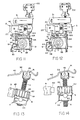
- Figure 1 shows a variable back adjustor 1 installed in a chair 2, having an articulated seat 3 and back 4.
- Adjustor 1 comprises a threaded spindle 5 connected with chair back 4, with a gear wheel 6 threadedly mounted on spindle 5.
- Gear wheel 6 is retained in a housing 7, which is attached to a relatively stationary portion of chair 2, such as control housing 8, whereby when chair back 4 is tilted, spindle 5 rotates gear wheel 6 in housing 7.
- a pawl 9 is shifted into and out of engagement with gear wheel 6 to selectively lock chair back 4 in a wide variety of different angular positions.
- adjustor 1 is shown installed in a chair control 15 of the known type referred to above; however, it is to be understood that adjustor 1 can be used in conjunction with a wide variety of different types of articulated and tilt back chairs, as will be readily appreciated by those skilled in the art.
- the illustrated chair control 15 comprises stationary control housing 8 in the form of a stamped metal dish.
- Stationary housing 8 includes a reinforcing bracket 16 extending along the forward edge thereof with an aperture 17 which, in conjunction with an aligned aperture in the base of housing 8, define a socket 14 in which the upper end of a support column 18 is received.
- Column 18 is supported on a pneumatic cylinder 19 to adjust the vertical height of the chair.
- an adapter 20 is provided to facilitate attaching pneumatic cylinder 19 with support column 18.
- a pair of left and right-hand, rear stretchers 23 support seat back 4, and are pivotally attached to the sides of stationary housing 8 by bearings 24.
- the rearward ends of the stretchers 23 form inwardly opening, U-shaped brackets 25 into which the ends of a tubular chair back support member 26 ( Figure 1) are received and retained.
- a coil-type return spring 27 is mounted in stationary housing 8 by a pair of concentric sleeves 28 and 29.
- a tension controller 30 is provided to adjust the tension of return spring 27.
- a pair of left and right-hand front stretchers 31 support the seat portion 3 of chair 2, and have their rearward ends 32 pivotally connected with rear stretchers 23 by pins 33. As best illustrated in Figure 3, the forward ends of front stretchers 31 are attached to stationary housing 7 by an adjustment mechanism 34.
- spindle 5 ( Figure 8) is pivotally attached to rear stretchers 23 by a bracket 40.
- Bracket 40 has a generally inverted U-shaped elevational configuration, with a clevis bracket 41 at the raised centre portion 39 thereof.
- An adapter sleeve 42 is attached to the upper end of spindle 5 by a pin 43, and adapter sleeve 42 is in turn pivotally retained in clevis bracket 41 by a pin 44 and retainer ring 45.
- bracket 40 includes four outwardly extending flanges 46, which are attached to rear stretchers 23 by suitable fasteners 47.
- Spindle 5 has a high helix thread to provide smooth running, and to minimize the force required to adjust the angular position of chair back 4.
- spindle 5 has a four start thread, with a helical angle of one revolution for every 17 mm of length.
- the precise pitch of the spindle threads may be varied to accommodate alternative applications.
- Bracket 52 has a generally inverted U-shaped elevational configuration, with an inclined forward edge 53 that is fixedly attached to column support bracket 16 by means such as welding or the like, as illustrated in Figure 7.
- Each arm 54 and 55 ( Figure 5) of bracket 52 includes an aperture 56, and a pair of clevis flanges 57 and 58 respectively for purposes to be described in greater detail hereinafter.
- gear wheel 6 has a two-part construction, comprising an upper disc 62, and a lower nut or sleeve 63.
- Disc 62 has a generally circular plan shape, and includes a plurality of radially extending slots 64, which form corresponding teeth 65 therebetween.
- the diameter of disc 62, and the number of teeth 65 desired is selected in accordance with the specific application.
- gear wheel 6 has a diameter of approximately 38 mm, with a total of twenty teeth 65.
- the illustrated chair back has well over forty different positions which provide adjustment in very small increments.
- a central bore 66 is positioned coaxially in disc 62, and includes a radially extending key 67 at the lower end thereof.
- the illustrated gear wheels include teeth 65, it is to be understood that the term "gear wheel” as used herein, also contemplates other types of protrusions, recesses, or other irregularities which could be used in conjunction with a mating pawl 9.
- the sleeve portion 63 of gear wheel 6 includes a threaded bore 70 in which spindle 5 is closely received.
- a ring 71 is integrally formed at the lower end of sleeve 63, and protrudes outwardly thereof.
- a pair of thrust bearings 72 are positioned on either side of ring 71, and associated pairs of thrust washers 73 are mounted on opposite sides of thrust bearings 72 to rotatably mount sleeve 63 in gear wheel housing 7.
- An inner tube 75 axially positions thrust bearings 72 and thrust washers 73 inside housing 7.
- a bearing plate 76 extends radially through diametrically opposite sides of housing 7 to securely retain sleeve 63 axially within housing 7.
- the upper end of sleeve 63 includes a keyway 77 in which the key 67 of disc 62 is received to rotatably lock disc 62 on sleeve 63. In this manner, disc 62 can be removed and replaced if necessary.
- Gear wheel 6 is preferably constructed of a suitable synthetic resin material to reduce wear and engagement noise.
- Bearing plate 76 extends radially outwardly of gear wheel housing 7, and the opposite ends are received through the mating apertures 56 in bracket 52, and are mounted in bearings 80 to pivotally retain gear wheel housing 7. Since both spindle 5 and gear housing 7 are pivotally mounted in their associated portions of the chair, when chair back 4 is tilted, spindle 5 will remain in alignment with gearwheel 6 to prevent any lateral strain or binding.
- Pawl 9 ( Figure 5) has a plate-like shape, and includes an integrally molded sleeve 81, which is received between the flanges 57 of bracket arm 54, and is pivotally retained therein by a pin 82 to define a first pivot point 79.
- Retainer pin 82 is positioned substantially parallel with spindle 5.
- pawl 9 is mounted in bracket 52 to pivot along a generally horizontal plane.
- the free end of pawl 9 includes an outwardly extending tab or dog 83, which is shaped to be closely received within the peripheral slots 64 of gear wheel 6 to positively lock gear wheel 6 against rotation.
- the outer end of dog 83 is V-shaped to facilitate engagement with gear wheel 6.
- Pawl 9 also includes a longitudinally extending slot 84 at the free end thereof, and a ball joint 85 at the opposite end for purposes to be described in greater detail hereinafter.
- Pawl 9 is also preferably constructed of a suitable synthetic resin material to reduce wear and engagement noise.
- over-centred spring arrangement 90 is provided to resiliently urge pawl 9 to either the fully locked position or the fully unlocked position.
- over-centred spring arrangement 90 comprises a looped wire spring 91 ( Figure 5) having a generally U-shaped plan configuration, with the free ends 92 thereof pivotally received through mating apertures in the flanges 58 of bracket arm 55 to define a second pivot point 93.
- the outer end 89 of spring 91 is received in the slot 84 at the free end of pawl 9, and pivots therein to define a third pivot point 94.
- Spring 91 is shaped so that the first, second and third pivot points 79, 93 and 94 respectively are aligned when pawl 9 is in an intermediate position between the fully locked and fully unlocked positions.
- pawl 9 is manipulated by a toggle arrangement 100, comprising a laterally extending shaft 101 rotatably mounted in forward stretchers 31.
- a toggle button 102 is attached to the free end of shaft 101, and extends through a mating aperture on the lower surface of the seat chair shell (not shown) for easy access by the occupant.
- Shaft 102 includes a crank 103 at a medial portion thereof.
- a link 104 includes a hook- shaped forward end 105 to pivotally attach the same to crank 103.
- the rearward end 106 of link 104 includes a socket which is attached to the ball 85 on pawl 9 with a snap fit.
- link 104 is longitudinally adjustable to ensure proper engagement between pawl 9 and gear wheel 6.
- Adjustor 1 provides a purely mechanical mechanism, which is capable of positively locking the chair back in a wide variety of different angular positions.
- the high helix thread of spindle 5 minimizes the force necessary to adjust chair back 4 and, in combination with gear wheel 6, greatly reduces the release force necessary to unlock the chair, even when very stiff return springs are used, as are required in multiple articulated chairs.
- the over-centred spring arrangement 90 ensures that pawl 9 is either fully engaged or fully disengaged from gear wheel 6, and particularly adapts adjustor 1 for use in a toggle button type of control.
Landscapes
- Health & Medical Sciences (AREA)
- Dentistry (AREA)
- General Health & Medical Sciences (AREA)
- Chairs For Special Purposes, Such As Reclining Chairs (AREA)
Claims (16)
Applications Claiming Priority (2)
| Application Number | Priority Date | Filing Date | Title |
|---|---|---|---|
| US375550 | 1982-05-06 | ||
| US06/375,550 US4494795A (en) | 1982-05-06 | 1982-05-06 | Variable back adjuster for chairs |
Publications (3)
| Publication Number | Publication Date |
|---|---|
| EP0094221A2 EP0094221A2 (fr) | 1983-11-16 |
| EP0094221A3 EP0094221A3 (en) | 1984-10-17 |
| EP0094221B1 true EP0094221B1 (fr) | 1987-02-25 |
Family
ID=23481317
Family Applications (1)
| Application Number | Title | Priority Date | Filing Date |
|---|---|---|---|
| EP83302571A Expired EP0094221B1 (fr) | 1982-05-06 | 1983-05-06 | Dossier réglable pour sièges |
Country Status (5)
| Country | Link |
|---|---|
| US (1) | US4494795A (fr) |
| EP (1) | EP0094221B1 (fr) |
| CA (1) | CA1209454A (fr) |
| DE (1) | DE3369833D1 (fr) |
| ES (1) | ES8501221A1 (fr) |
Families Citing this family (36)
| Publication number | Priority date | Publication date | Assignee | Title |
|---|---|---|---|---|
| GB8406697D0 (en) * | 1984-03-14 | 1984-04-18 | Teleflex Morse Ltd | Seat recline unit |
| US4720142A (en) * | 1986-04-10 | 1988-01-19 | Steelcase Inc. | Variable back stop |
| US4979778A (en) * | 1989-01-17 | 1990-12-25 | Brayton International, Inc. | Synchrotilt chair |
| US5029940A (en) * | 1990-01-16 | 1991-07-09 | Westinghouse Electric Corporation | Chair tilt and chair height control apparatus |
| US5318346A (en) * | 1991-05-30 | 1994-06-07 | Steelcase Inc. | Chair with zero front rise control |
| DK0517934T3 (da) * | 1991-06-10 | 1995-08-21 | Siemens Ag | Tandlæge-patientstol med svingbart ryglæn |
| US5203853A (en) * | 1991-09-18 | 1993-04-20 | Herman Miller, Inc. | Locking chair tilt mechanism with torsion bar |
| JP2919131B2 (ja) * | 1991-10-22 | 1999-07-12 | 株式会社イトーキクレビオ | 椅子の傾動制御装置 |
| US5328242A (en) * | 1992-03-18 | 1994-07-12 | Steelcase Inc. | Chair with back lock |
| US5282670A (en) * | 1992-04-20 | 1994-02-01 | Steelcase Inc. | Cable actuated variable stop mechanism |
| BR9307983B1 (pt) * | 1992-06-15 | 2010-07-27 | estrutura de assento e método de fabricação da mesma. | |
| US5630643A (en) * | 1993-06-01 | 1997-05-20 | Steelcase Inc | Upholstered chair with two-piece shell |
| US5427434A (en) * | 1993-07-30 | 1995-06-27 | Leggett & Platt, Incorporated | Chair tilt and height adjustment mechanism |
| US5577807A (en) * | 1994-06-09 | 1996-11-26 | Steelcase Inc. | Adjustable chair actuator |
| EP0763991A4 (fr) * | 1994-06-10 | 2000-10-04 | Haworth Inc | Fauteuil ergonomique |
| IE80799B1 (en) * | 1994-08-17 | 1999-02-24 | Ashfield Eng Co Wexford Ltd | A chair tilting mechanism |
| US5782536A (en) * | 1995-02-17 | 1998-07-21 | Steelcase Inc. | Modular chair construction and method of assembly |
| US5765914A (en) * | 1995-06-07 | 1998-06-16 | Herman Miller, Inc. | Chair with a tilt control mechanism |
| US5676425A (en) * | 1996-03-19 | 1997-10-14 | R.A.M. Machines (1990) Ltd. | Releasable lock forchair control mechanism |
| US5810439A (en) * | 1996-05-09 | 1998-09-22 | Haworth, Inc. | Forward-rearward tilt control for chair |
| US5909924A (en) * | 1997-04-30 | 1999-06-08 | Haworth, Inc. | Tilt control for chair |
| US6250715B1 (en) | 1998-01-21 | 2001-06-26 | Herman Miller, Inc. | Chair |
| US6598936B1 (en) | 2001-04-11 | 2003-07-29 | Michael N. Klein | Multi-task mid-pivot chair control mechanism |
| US6585320B2 (en) | 2001-06-15 | 2003-07-01 | Virco Mgmt. Corporation | Tilt control mechanism for a tilt back chair |
| US7625046B2 (en) * | 2002-03-29 | 2009-12-01 | Garrex Llc | Task chair |
| US20050046258A1 (en) * | 2003-07-09 | 2005-03-03 | Sanchez Gary L. | Task chair |
| US7396082B2 (en) | 2002-03-29 | 2008-07-08 | Garrex Llc | Task chair |
| US7040703B2 (en) * | 2002-03-29 | 2006-05-09 | Garrex Llc | Health chair a dynamically balanced task chair |
| US7066538B2 (en) * | 2003-12-30 | 2006-06-27 | Hni Technologies, Inc. | Chair with tilt lock mechanism |
| US7500718B2 (en) * | 2004-05-14 | 2009-03-10 | Haworth, Inc. | Tilt tension mechanism for chair |
| ES2527757T3 (es) * | 2005-03-01 | 2015-01-29 | Haworth, Inc. | Mecanismo de regulación de tensión |
| CN102772053A (zh) | 2007-01-29 | 2012-11-14 | 赫尔曼米勒有限公司 | 座位结构及其使用方法 |
| DE102008045489A1 (de) * | 2008-02-22 | 2009-09-03 | Bock 1 Gmbh & Co. Kg | Mechanik für einen Bürostuhl |
| SG11201500879UA (en) * | 2012-09-05 | 2015-03-30 | Godrej & Boyce Mfg Co Ltd | Chair with adjustable backrest and seat |
| CN108371436B (zh) * | 2018-04-25 | 2023-10-27 | 严澄宇 | 弹力跷跷板式的自由倾仰机构及自由调节转椅 |
| SE544527C2 (en) * | 2019-01-18 | 2022-07-05 | Flokk Ab | A tilt locking device for a chair seat |
Family Cites Families (20)
| Publication number | Priority date | Publication date | Assignee | Title |
|---|---|---|---|---|
| US964394A (en) * | 1909-10-11 | 1910-07-12 | Charles M Stuart | Lifting-jack. |
| US1302212A (en) * | 1919-03-03 | 1919-04-29 | Andrew J Phillips | Reclining-chair. |
| US2579305A (en) * | 1948-01-26 | 1951-12-18 | Sturgess Inc | Position-adjusting mechanism |
| US3059890A (en) * | 1959-09-03 | 1962-10-23 | Bostrom Corp | Seat for highway trucks |
| US3046055A (en) * | 1960-02-19 | 1962-07-24 | Anderson Co | Position-adjusting mechanism |
| US3127788A (en) * | 1960-12-29 | 1964-04-07 | Anderson Co | Position-retaining device |
| US3062584A (en) * | 1961-01-31 | 1962-11-06 | Ford Motor Co | Vehicular seat assembly |
| DE1429262C3 (de) * | 1963-07-25 | 1974-08-29 | The Anderson Co., Gary, Ind. (V.St.A.) | Einrichtung zum Festlegen der Stellung der einstellbaren Rückenlehne eines Sessels |
| US3246868A (en) * | 1964-07-14 | 1966-04-19 | Anderson Co | Position-retaining device |
| US3369841A (en) * | 1964-12-10 | 1968-02-20 | Lear Siegler Inc | Positioning mechanism for a reclining seat |
| US3356411A (en) * | 1965-02-18 | 1967-12-05 | Lear Siegler Inc | Seat back positioning mechanism |
| US3339975A (en) * | 1966-04-05 | 1967-09-05 | Lear Siegler Inc | Reclining seat assembly |
| US3398986A (en) * | 1966-12-08 | 1968-08-27 | Lear Siegler Inc | Seat positioning mechanism |
| CA869338A (en) * | 1969-09-23 | 1971-04-27 | Doerner Products Co. Limited | Chair control with torsion spring with tilting seat and chair back |
| US3799486A (en) * | 1972-08-31 | 1974-03-26 | Steelcase Inc | Height adjusting mechanism |
| US3991965A (en) * | 1976-01-27 | 1976-11-16 | Gf Business Equipment, Inc. | Chair height adjusting mechanism |
| GB1604916A (en) * | 1978-02-10 | 1981-12-16 | Inventec Licensing Bv | Seats for children |
| US4291914A (en) * | 1980-01-10 | 1981-09-29 | Hoover Universal, Inc. | Adjustable seat hinge |
| US4375301A (en) * | 1980-05-01 | 1983-03-01 | Steelcase Inc. | Chair seat adjustment assembly |
| DE3039656A1 (de) * | 1980-10-21 | 1982-05-27 | Wilkhahn Wilkening & Hahne | Sitzmoebel mit in verschiedenen stellungen arretierbarem sitz |
-
1982
- 1982-05-06 US US06/375,550 patent/US4494795A/en not_active Expired - Lifetime
-
1983
- 1983-05-02 CA CA000427174A patent/CA1209454A/fr not_active Expired
- 1983-05-05 ES ES522110A patent/ES8501221A1/es not_active Expired
- 1983-05-06 DE DE8383302571T patent/DE3369833D1/de not_active Expired
- 1983-05-06 EP EP83302571A patent/EP0094221B1/fr not_active Expired
Also Published As
| Publication number | Publication date |
|---|---|
| EP0094221A3 (en) | 1984-10-17 |
| CA1209454A (fr) | 1986-08-12 |
| US4494795A (en) | 1985-01-22 |
| DE3369833D1 (en) | 1987-04-02 |
| ES522110A0 (es) | 1984-11-16 |
| EP0094221A2 (fr) | 1983-11-16 |
| ES8501221A1 (es) | 1984-11-16 |
Similar Documents
| Publication | Publication Date | Title |
|---|---|---|
| EP0094221B1 (fr) | Dossier réglable pour sièges | |
| JP3544709B2 (ja) | 椅子 | |
| JP3689138B2 (ja) | 椅子座部の傾斜調節及びロック機構 | |
| US5029940A (en) | Chair tilt and chair height control apparatus | |
| US4830434A (en) | Adjustable head rest device for vehicle | |
| KR950014763B1 (ko) | 사무용 의자 | |
| US5577807A (en) | Adjustable chair actuator | |
| US5203853A (en) | Locking chair tilt mechanism with torsion bar | |
| EP1047319B1 (fr) | Mecanisme de commande d'une chaise a plusieurs positions a reglage synchronise du siege et du dossier | |
| JP3663217B2 (ja) | いす | |
| CA2161068C (fr) | Dispositif d'inclinaison de fauteuil attenuant les secousses | |
| US4222543A (en) | Vertical and angular adjustment device for vehicle seats | |
| JPH0734771B2 (ja) | 座家具 | |
| EP3556252B1 (fr) | Mécanisme d'inclinaison pour chaise et chaise | |
| US5507200A (en) | Combination motorcycle kickstand mechanism and transmission forward control unit | |
| JPH03501832A (ja) | 車輛運転者周りの調節対象物調節装置 | |
| US20250255412A1 (en) | Double angle back support adjustment | |
| JPH0675530B2 (ja) | 改良された背支持手段 | |
| US5421640A (en) | Back-rest hinge for a vehicle seat with a seat support and a back-rest hinged to it | |
| JPH0152204B2 (fr) | ||
| KR950003046B1 (ko) | 시트 조정 장치 | |
| PL181879B1 (pl) | Urzadzenie do regulacji kata nachylenia oparcia wzgledem siedziska, zwlaszcza krzesel PL PL PL | |
| US6196633B1 (en) | Retractor for a seat belt | |
| US4260190A (en) | Hinge fittings | |
| US5121966A (en) | Adjustable recliner chair |
Legal Events
| Date | Code | Title | Description |
|---|---|---|---|
| PUAI | Public reference made under article 153(3) epc to a published international application that has entered the european phase |
Free format text: ORIGINAL CODE: 0009012 |
|
| AK | Designated contracting states |
Designated state(s): DE FR GB |
|
| PUAL | Search report despatched |
Free format text: ORIGINAL CODE: 0009013 |
|
| AK | Designated contracting states |
Designated state(s): DE FR GB |
|
| 17P | Request for examination filed |
Effective date: 19850228 |
|
| GRAA | (expected) grant |
Free format text: ORIGINAL CODE: 0009210 |
|
| AK | Designated contracting states |
Kind code of ref document: B1 Designated state(s): DE FR GB |
|
| REF | Corresponds to: |
Ref document number: 3369833 Country of ref document: DE Date of ref document: 19870402 |
|
| ET | Fr: translation filed | ||
| PLBE | No opposition filed within time limit |
Free format text: ORIGINAL CODE: 0009261 |
|
| STAA | Information on the status of an ep patent application or granted ep patent |
Free format text: STATUS: NO OPPOSITION FILED WITHIN TIME LIMIT |
|
| 26N | No opposition filed | ||
| PGFP | Annual fee paid to national office [announced via postgrant information from national office to epo] |
Ref country code: GB Payment date: 19930413 Year of fee payment: 11 |
|
| PGFP | Annual fee paid to national office [announced via postgrant information from national office to epo] |
Ref country code: FR Payment date: 19930507 Year of fee payment: 11 |
|
| PGFP | Annual fee paid to national office [announced via postgrant information from national office to epo] |
Ref country code: DE Payment date: 19930525 Year of fee payment: 11 |
|
| PG25 | Lapsed in a contracting state [announced via postgrant information from national office to epo] |
Ref country code: GB Effective date: 19940506 |
|
| GBPC | Gb: european patent ceased through non-payment of renewal fee |
Effective date: 19940506 |
|
| PG25 | Lapsed in a contracting state [announced via postgrant information from national office to epo] |
Ref country code: FR Effective date: 19950131 |
|
| PG25 | Lapsed in a contracting state [announced via postgrant information from national office to epo] |
Ref country code: DE Effective date: 19950201 |
|
| REG | Reference to a national code |
Ref country code: FR Ref legal event code: ST |