EP0094240A2 - Dispositif de chargement automatique pour disques flexibles - Google Patents
Dispositif de chargement automatique pour disques flexibles Download PDFInfo
- Publication number
- EP0094240A2 EP0094240A2 EP83302615A EP83302615A EP0094240A2 EP 0094240 A2 EP0094240 A2 EP 0094240A2 EP 83302615 A EP83302615 A EP 83302615A EP 83302615 A EP83302615 A EP 83302615A EP 0094240 A2 EP0094240 A2 EP 0094240A2
- Authority
- EP
- European Patent Office
- Prior art keywords
- disk
- disk drive
- floppy
- disks
- drive
- Prior art date
- Legal status (The legal status is an assumption and is not a legal conclusion. Google has not performed a legal analysis and makes no representation as to the accuracy of the status listed.)
- Withdrawn
Links
Images




Classifications
-
- G—PHYSICS
- G11—INFORMATION STORAGE
- G11B—INFORMATION STORAGE BASED ON RELATIVE MOVEMENT BETWEEN RECORD CARRIER AND TRANSDUCER
- G11B17/00—Guiding record carriers not specifically of filamentary or web form, or of supports therefor
- G11B17/08—Guiding record carriers not specifically of filamentary or web form, or of supports therefor from consecutive-access magazine of disc records
- G11B17/10—Guiding record carriers not specifically of filamentary or web form, or of supports therefor from consecutive-access magazine of disc records with horizontal transfer to the turntable from a stack arranged with a vertical axis
Definitions
- This invention is generally related to electronic computer devices and more particularly pertains to devices for automatically feeding floppy disks into and out of computer disk drives.
- Floppy computer disks (or diskettes) are used in the data processing industry for storing computer programs, data, etc.
- the floppy disks are flat, circular sheets of plastic having magnetic particles which store digital data.
- the plastic disks are stored inside square enve - lopes or jackets which prevent the disk from being damaged and provide convenient storage of the disks.
- the floppy disk consists of the circular plastic disk which is permanently enclosed by the square envelope.
- the plastic disk has a central hole which is designed to fit over the hub or spindle of a computer disk drive so that the plastic disk may be rotated inside the envelope.
- a magnetic recording/detecting head is used inside the disk drive in order to read or write digital data from the spinning plastic disk.
- the floppy computer disk is a particularly convenient and compact device for storing relatively large amounts of digital data.
- Floppy disks are routinely used for personal computers and smaller computer systems including microcomputers and minicomputers. Because there is a very large market for computer programs that operate with such personal computers or small computer systems, suppliers of computer programs distribute a large number of floppy disks to computer users. It is frequently necessary, in the computer program supply business, to provide revised or updated versions of programs which is often done by distributing new program copies on floppy disks. Because the computer industry is a very volatile and fast-moving market, it is desirable for computer program suppliers to have a large number of computer program copies on floppy disks available for immediate delivery when revisions, updates, or new programs are announced.
- a method often used in the production of floppy disk copies is to sequentially copy the information from a master disk onto a large number of copy disks which then each have the same information as recorded on the master disk.
- Loader assemblies have been used in the past in order to sequentially feed floppy disks into a floppy disk drive and in order to sort the floppy disks into two separate bins as they exit from the disk drive.
- Prior loaders have used a picker mechanism which serves to slide the lowest floppy disk in a stack of floppy disks toward a set of rollers which pull the disk into a disk drive. In such prior loaders, the floppy disks were sorted into two separate horizontally separated bins upon being ejected from the disk drive.
- prior loader design is very effective in automatically feeding floppy disks through a floppy disk computer drive, but requires very time-consuming alignment procedures during manufacture and may require very delicate realignment procedures after the loader has been used for some time. Also, such prior loaders have experienced some problems with jamming and damage to floppy disks. Although such problems do not destroy the usefulness of prior loaders, the problems do reduce the loader reliability which may be disadvantageous for high-volume disk handling applications and for loaders used in locations where maintenance service is not readily available.
- the improved automatic floppy disk loader apparatus of this invention includes an alignment framework, or enclosure, mounted directly to the disk drive which serves to align disk transporting rollers, disk position sensors, and a disk closing solenoid with the disk drive so that a unitary assembly is formed.
- the alignment enclosure is constructed so that, during manufacture, the drive, rollers, disk closing solenoid and sensors are fixed in predetermined relative spatial positions so that proper alignment is assured.
- the use of such an alignment enclosure also ensures that misalignment between the disk, rollers and sensors does not occur during use of the loader due to vibration, temperature changes, etc.
- roller alignment frame which serves to hold the three rollers together with predetermined spacing and further allows the rollers to be attached, as a unitary group, to the alignment framework surrounding the computer disk drive.
- the roller alignment framework is preferably a rigid framework which resists bending or twisting and thus ensures that floppy disks are fed uniformly and smoothly into and out of the computer disk drive.
- the improved automatic floppy disk loader apparatus of this invention also includes a pivoting flap which is operated by a solenoid so that floppy diskettes which are ejected from the computer disk drive are automatically sorted between two vertically separated floppy disk bins.
- the use of such a pivoting flap ensures that the diskettes are reliably sorted into a bin which contains only "accepted” diskettes and a bin which contains only "rejected” diskettes.
- the two diskette bins for receiving diskettes ejected from the disk drive are preferably formed in a single bin assembly which is removably mounted to the loader so that the bin assembly and the diskettes contained therein may be easily removed from the loader.
- the improved automatic floppy disk loader apparatus of this invention also includes an improved picker mechanism for automatically sliding a single diskette from the bottom of the stack of diskettes in the supply hopper of the loader.
- the improved picker mechanism includes a low friction base plate which has an integral groove for guiding the sliding motion of a picker block.
- the picker mechanism also includes a hinged, spring-loaded feed inhibit bracket which is designed to prevent diskettes from inadvertently, prematurely sliding into the disk drive.
- the sliding picker block is shaped to automatically move the feed inhibit bracket downwards, out of the way as the sliding picker block moves forward and pushes a diskette through a pair of rollers and into the disk drive.
- the hinged feed inhibit bracket reduces the chance of loader malfunction due to metal fatigue and provides a reliable, spring-acting closure.
- the integral groove in the low friction picker baseplate ensures that the picker block travels smoothly along a straight path.
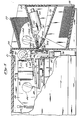
- a floppy disk loader 20 is incorporated into a computerized floppy disk handling machine 21.
- the floppy disk handling machine 21 is one example of a device in which the loader 20 may be used.
- the loader 20 may also be used as part of a floppy disk handling system in which large numbers of loaders similar to the loader 20 may be connected to a central processor so that each of the loaders may be individually controlled by the central processor.
- the loader 20 may be used as part of a system for the large-scale formatting, initializing, verifying, or copying of floppy computer disks.
- the loader 20 includes a hopper base plate 24 onto which a stack of floppy computer disks 22 may be placed.
- the loader 20 includes a pair of floppy disk bins 26 and 28 mounted one above the other, beneath the supply hopper base plate 24.
- the function of the floppy disk loader 20 is to feed floppy disks from the stack 22, one.at a time, into a computer disk drive (not shown) and, after processing of the floppy disks has been completed inside the disk drive, to sort the disks so that each disk is placed either in bin 26 or bin 28.
- bin 28 will contain disks which have passed an acceptance test
- bin 26 will contain disks which have not passed an acceptance test.
- the loader 20 is intended to operate unattended, without operator intervention, so that a large number of disks placed in the stack 22 may be automatically processed. It is important that the loader 20 operates in a smooth fashion so that floppy disks do not become jammed or damaged inside the loader 20 and so that the floppy disks are reliably sorted between the bins 26 and 28.
- floppy disks are moved from the bottom of the stack 22, one at 'a time, by a picker solenoid 30 which pushes a picker block 32 which, in turn, grips the jacket hole of the lowest floppy disk on the stack 22.
- the actuation travel of the solenoid 30 . is long enough so that the floppy disk at the bottom of the stack 22 is pushed into and through the space between the rollers 34 and 36.
- the roller 36 is connected to a motor (not shown).
- the roller 34 acts as an idler so that floppy disks are pulled through the set of rollers 34 and 36.
- the function of the rollers 34 and 36 is to pull disks from the picker block 32 and move them into a disk drive (not shown).
- the diskette 40 is shown in the position it would assume inside the disk drive (not shown) after exiting from between the rollers 34 and 36.
- a frame solenoid 42 is positioned over the diskette 40 so that the solenoid 42 is substantially aligned with the hub hole 44 of the diskette 40.
- the function of the frame solenoid 42 is to push the hinged carrier frame (not shown) of the disk drive (not shown) downward so that the diskette 40 is reliably mounted inside the disk drive, and so that the disk drive frame does not become twisted or offset in an undesired manner.
- a disk eject lever 48 is connected to a rotary solenoid 46 which is positioned so that actuation of the solenoid 46 will cause the floppy diskette 40 to be pushed out of the disk drive.
- the rotary solenoid 46 pushes the diskette 40 into and through the space between the rollers 36 and 38.
- the rotary solenoid 46 is actuated after the linear solenoid 42 has been released so that the disk drive is opened.
- the purpose of the rotary solenoid 46 and the lever 48 is to move the diskette 40 out of the disk drive after processing of the diskette has been completed.
- the central roller 36 is rotated by a motor (not shown) and the roller 38 acts as an idler so that the diskette 40 is pulled from the disk drive.
- the pivoting flap 50 is mounted adjacent to the rollers 36 and 38 in order to guide the travel of diskettes passing out from between the rollers 36 and 38.
- the position shown for flap 50 in Figure 2 will cause a diskette travelling through the rollers 36 and 38 to be placed in the "accept" bin 28.
- the pivoting flap 50 is in the position 52 (shown in phantom in Figure 2), diskettes ejected from between the rollers 36 and 38 will travel over the flap 50 and be placed in the "reject" bin 26.
- alignment side plates 54 and 56 are securely mounted to opposite sides of the disk drive 58 and serve to ensure that components of the floppy diskette loader 20 are held in rigid alignment.
- the side plates 54 and 56 are preferably folded, metal sheets which are precisely drilled with location holes for the various components of the diskette loader 20 so that during manufacture, the side plates 54 and 56 serve to insure that correct relative spatial positioning will automatically occur for the various components. Since the side plates 54 and 56 are securely attached to the disk drive 58 and are of unitary construction, the side plates.54 and 56 serve to insure that the relative alignment of the components of the diskette loader 20 do not become disturbed due to vibration or temperature changes which may occur during use of the loader 20.
- the disk drive 58 has a spindle hub 60 which rotates in order to spin floppy diskettes when in use and has a cone 62 which may be pushed downwards onto the spindle hub 60 in order to force the hub hole of the floppy diskette over the spindle 60.
- the cone 62 and spindle 60 are clamped together so that the floppy diskette is trapped between the cone 62 and hub 60 and so that rotation of the hub 60 will cause the floppy diskette to rotate.
- the spindle hub 60 is mounted in the base of the disk drive 58 and the cone 62 is mounted on a hinged frame 64 which is pivotably mounted on the upper side of the disk drive 58.
- the frame 64 is normally pivoted into an open or up position when floppy diskettes are to be loaded into or removed from the disk drive 58, and the frame 64 is pushed into a closed or down position when a floppy diskette is inside the drive 58.
- the disk drive 58 shown in Figure 3 is typical of a variety of conventional, commercially available floppy diskette computer drives.
- the linear frame solenoid 42 is mounted to a cross bracket 66 which is securely attached to and extends between the alignment side plates 54 and 56.
- the linear solenoid 42 is mounted above the disk drive frame 64 so that actuation of the solenoid 42 will cause the frame 64 to move down, thus closing the disk drive 58.
- a spring bracket 68 and contact bracket 70 are securely attached to the frame 64 and provide for spring-assisted opening of the disk drive 58, and a point of contact for closing of the disk drive 58 by the solenoid 42, respectively.
- the contact plate 70 is positoned on the frame 64 so that the forces exerted by the linear solenoid 42 are substantially close to the cone 62 and spindle 60, so that undesirable twisting or bending of the frame 64 does not occur as the solenoid 42 is used.
- the frame 64 is supported on the base of the disk drive 58 by a pair of spring hinges 72 and 74 which are usually made of spring steel and provide spring-loaded tension for the frame 64 so that the disk drive 58 will automatically open.
- Spring hinges 72 and 74 are normally placed close to opposite sides of the disk drive 58 so that twisting or bending of the frame 64 is avoided, and the frame 64 is confined to moving straight up and down.
- any external twisting or bending forces may tend to fatigue or. distort the spring hinges 72 and 74 and thus lead to their premature failure. Therefore, the linear frame solenoid 42 and contact plate 70 are centrally mounted with respect to the frame 64 so that off-center loading of the frame 64 and premature failure of the spring hinges 72 and 74 is avoided.
- the disk ejection prevention mechanism 76 is mounted - to the forward end of the disk drive 58 and includes a solenoid 78 and ejection prevention bar 80 which may be operated to prevent floppy diskettes from being inadvertently, prematurely ejected from the disk drive 58.
- a direct current motor 82 is securely mounted to the side alignment plate 54 and is connected to rotate the drive roller 36 through a drive belt 84. It is preferable that the motor 82 be a direct current, low-inertia motor so that rotation of the drive roller 36 will stop quickly should a diskette become jammed inside the diskette loader 20. The fact that the motor 82 is of the low-inertia type helps to prevent jammed diskettes from becoming mutilated or folded. The fact that the motor 82 is operated from a direct current power source allows the motor 82 to be operated intermittently, which helps to prevent undesired noise signals from interfering with the delicate reading and writing operations performed inside the disk drive 58.
- the drive rollers 34, 36 and 38 are mounted inside a roller alignment frame 86 which ensures that the rollers 34, 36 and 38 are held in correct relative spatial position.
- the alignment frame 86 is square and true so that when the frame 86 is mounted in the mounting holes 88 and 90 of the alignment side plates 54 and 56, respectively, the rollers 34, 36 and 38 will be automatically, correctly aligned with the disk drive 58.
- the roller alignment plate 86 consists of side plates 92 and 94, and cross bars 96 and 98 which extend between the side plates 92 and 94.
- the side plates 92 and 94 include bearing holes for the drive rollers 34, 36 and 38 so that the relative positions of the drive rollers is predefined and so that the drive rollers 34, 36 and 38 are held in alignment with each other.
- the side plates 92 and 94 are rigidly connected to the cross bars 96 and 98 in the alignment frame 86 so that the alignment frame 86 is held rigidly together and avoids twisting or warping. Because of the unitary _ structure of the alignment frame 86, it ensures that the rollers 34, 36 and 38 are correctly, automatically aligned during manufacture and further ensures that relative alignment of the rollers does not change during use due to vibration or temperature changes. The mounting of the alignment frame 86 on the alignment side plates 54 and 56 ensures that the relative alignment of the rollers 34, 36 and 38 with the disk drive 58 automatically, correctly occurs during manufacture and that the alignment is maintained during use and does not change due to vibrations or temperature changes.
- a disk position sensor bracket 100 is mounted on the side plate 56 in order to detect the position of floppy diskettes as they move into or are ejected from the disk drive 58.
- the bracket 100 is equipped with a pair of infrared photoelectric transducers, each of which consists of an infrared light transmitter and an infrared light detector. Detection of the position of a floppy diskette occurs by detection of when the beam of infrared light between transmitter and detector is interrupted by the presence of a floppy diskette. It is preferable that the disk position sensor bracket 100 make use of infrared light so that ambient room lighting does not interfere with the reliable detection of diskette position.
- the bracket 100 is securely mounted to the alignment side plate 56 so that relative alignment between the bracket 100 and the disk drive 58 is predefined by the location of mounting holes in the plate 56 so that correct alignment is automatically achieved during manufacture, and correct alignment is reliably maintained during use of the diskette loader 20.
- a frame position sensor bracket 102 is mounted on the side plate 56 in order to sense the position of the frame 64 by detecting the location of the bracket 68.
- the frame position sensor bracket 102 is substantially identical in construction to the diskette position sensor bracket 100.
- the frame position sensor bracket 102 is mounted in predefined mounting holes on the side plate 56 so that correct alignment is automatically achieved during manufacture and so that correct alignment of the bracket 102 is maintained during use of the diskette loader 20 even though vibrations or changes in temperature may occur.
- the pivoting plate 50 is mounted in front of the roller alignment frame 86 and is actuated by a rotary solenoid 104 acting through a crank bar 106.
- the crank bar 106 is rotatably mounted on a pin 108 attached to the pivoting flap 50.
- FIG 4 a portion of the floppy disk loader 20 is shown assembled and corresponds to the parts shown in Figure 3 which are shown unassembled, in an exploded drawing.
- the disk drive 58 spans the horizontal distance between the alignment side plates 54 and 56.
- the plates 54 and 56 are to be secured to a chassis (not shown) in order to support the disk drive 58.
- the side plates 54 and 56 and the disk drive 58 form a unitary assembly which serves to enclose, support and align the components which are used for moving floppy diskettes into and out of the disk drive 58.
- the disk drive 58 and side plates 54 and 56 form a subassembly which holds a roller alignment frame 86, frame solenoid 42, diskette ejector solenoid 46, and sensor brackets 100 and 102 in pre-defined relative spatial alignment.
- the disk drive 58 is rigidly mounted to each of the alignment side plates 54 and 56 so that the disk drive 58 is not allowed to shift or move about during use, and thus the alignment is maintained.
- the roller alignment frame 86 is similarly securely attached to the side alignment plates 54 and 56 so that changes in alignment are prevented.
- the cross-bracket 66 is used to securely mount the linear solenoid 42 between the alignment side plates 54 and 56 so that the linear solenoid 42 may be used to force the carrier frame 64 downwards by pressing on the contact bracket 70.
- the side plates 54 and 56 serve to ensure that the linear solenoid 42 is kept in position directly over the contact bracket 70 and ensures that the force provided by the solenoid 42 is applied straight down and does not cause twisting of the frame 64.
- the alignment side plates 54 and 56 also serve as mounting supports for a printed circuit board 110 which is positioned to slide vertically into card guides on the plates 54 and 56.
- the printed circuit board 110 is positioned to the rear of the disk drive 58 and is held by the plates 54 and 56 in a convenient position for servicing access.
- the printed circuit board 110 provides electrical interfacing for the disk drive 58.
- a picker wedge 112 fits into the circular hole in the jacket of the lowest floppy diskette on the stack 22.
- the wedge 112 fits into and grips the lowest floppy diskette so that as the picker block 32 slides forwards and downwards towards the disk drive 58, the lowest floppy diskette moves through the roller frame 86 and into the disk drive 58.
- the feed inhabit bracket 114 serves to- prevent floppy diskettes from inadvertently, prematurely leaving the stack 22 and falling into the roller frame 86.
- the feed inhibit bracket 114 is automatically moved downwards as the picker block 32 slides forward and downwards, so that the floppy diskette gripped by the wedge 112 may enter the roller frame 86.
- the motor 82 is actuated in order to pull the.diskette through the roller frame 86, towards the disk drive 58, and off of the wedge 112.
- the ejection prevention bar 80 is moved from its rest position at 80a to the position shown at 8 0 b which serves to prevent the floppy diskette from being inadvertently, prematurely ejected from the disk drive 58 towards the roller frame 86.
- the frame 64 is closed after the diskette has entered the disk drive 58 so that the diskette may be rotated and digital data may be read from and written onto the diskette. Closing of the frame 64 is accomplished by actuation of the linear frame solenoid 42.
- the frame 64 is opened by deactuation of the solenoid 42 which allows a retraction spring 117 (attached to the frame 64) and the spring hinges 72 and 74 (see Figure 3) to pull the frame 64 upwards.
- the ejection prevention bar 80 is lowered to the position 80a by deactuation of the solenoid 78 so that the floppy diskette may be ejected from inside the disk drive 58.
- the rotary solenoid 46 When the floppy diskette inside the disk drive 58 is to be ejected, the rotary solenoid 46 is actuated so that the eject lever 48 pushes the floppy diskette into and through the space between the lower two rollers in the roller frame 86. Rotation of the motor 82 causes the floppy diskette to be pulled through the roller frame 86 towards the pivoting flap 50.
- the position of the pivoting flap 50 is set by the rotary solenoid 104 which acts through the connecting bar linkage 106.
- the rotary solenoid 104 places the connecting bar 106 in the position labeled 106a, the pivoting flap 50 assumed the position labeled 50a and floppy diskettes ejected through the roller frame 86 will pass under the pivoting flap 50 and be placed on top of a stack in the "accept" bin 28.
- Operation of the motor 82, bin control selection solenoid 104, picker solenoid 30, ejection prevention solenoid 78, frame solenoid 42, ejection solenoid 46, and disk drive 56 is preferably placed under the control of a computer processor of conventional construction so that the sequencing of operations provides for smooth movements of floppy diskettes into and out of the disk drive 58.
- the bins 26 and 28 are preferably a part of a unitary bin assembly which may be removed from the floppy disk processing machine 21 so that the floppy disks placed in the bins 26 and 28 may be easily removed.
- the picker base plate 24 is mounted to allow slight manual adjustment of the discharge slot gap 123 through which the floppy diskettes in the stack 22 must travel through.
- the gap 123 is defined by the space between the hopper wall and the base plate 24. It is important that the gap 123 be a precisely defined width so that one and only one floppy diskette may pass through the gap 123 at a single time.
- the preferred mounting arrangement for the base plate 24 on the machine 21 is to have mounting bolts connecting to the sides of the base plate 24 in which the holes for the bolts at the lower end of the base plate 24 are slightly oversized, thus allowing the base plate 24 to be slightly pivoted, in order to allow adjustment of the width of the gap 123.
- the picker wedge 112 is a tapering, metal block having a generally "T" shaped cross section which fits into and slides along a slot 116 which extends through the picker base plate 24.
- the wedge 112 is shaped to grip a circular hole in a diskette jacket for pushing the diskette forward, and is tapered to allow the diskette to continue moving in a forward direction over the wedge 112 as the rollers 34 and 36 (see Figure 2) pull the diskette into the disk drive 58.
- the wedge 112 is bolted to the picker block 32 which is on the underside of the picker base plate 24. Because of the "T" shaped cross section of the wedge 112, the wedge 112 and picker block 32 are constrained to slide back and forth on the picker base plate 24, along the slot 116.
- the feed inhibit bracket 114 has a lip 118 which extends upwards through a cutout 120 in the picker base plate 24.
- The.feed inhibit bracket 114 is normally in an "up” position so that the lip 118 projects through the cutout 120 and prevents diskettes from sliding off the base plate 24 and into the disk drive 58.
- the feed inhibit bracket 114 is automatically moved to a "down" position which lowers the lip 118 in the cutout 120 below the surface level of the base plate 24, so that a diskette may be pushed by the wedge 112 towards the disk drive 58.
- An optical sensor 121 is provided on the surface of the base plate 24 so that the presence of floppy diskettes on the base plate 24 may be determined.
- the sensor 121 detects when light is obstructed by diskettes overlying the sensor 121 on the base plate 24.
- the picker block 32 is equipped with a pair of retraction springs 122 and 124 which serve to automatically pull the picker block 32 backwards and upwards when the solenoid 30 is deactu- ated.
- the retraction springs 122 and 124 are mounted symmetrically to the picker block 32 so that it is retracted smoothly without twisting or binding.
- the picker block 32 slides in a flat bottomed recess groove 126 in the lower surface of the base plate 24.
- the groove 126 serves to constrain the block 32 to a sliding motion along a straight line.
- the picker block 32 is equipped with a tapered front nose 128 at its forward end which is shaped to fit under the feed inhibit bracket 114. As the picker block 32 slides forward in the groove 126, the nose 128 pushes the bracket 114 downwards so that the - lip 118 is pulled beneath the surface of the base plate 24 and a floppy diskette is allowed to slide from the bottom of the stack 22 into the disk drive 58.
- the feed inhibit bracket 114 is mounted to the underside of the base plate 24 by spring loaded hinge joints 130 and 132 which allow the bracket 114 to pivot upwards and downwards and which spring bias the bracket 114 in an "up" position so that when the picker block 32 is retracted, the lip 118 projects from the cutout 120 and inhibits floppy disks from sliding towards the disk drive 58.
- the spring loaded hinges 130 and 132 allow the bracket 114 to pivot upwards and downwards without causing undue mental fatigue. Because of the mechanical relationship between the picker block 32, nose 128 and feed inhibit bracket 114, the solenoid 30 serves to both slide the picker block 32 forward and pull the feed inhibit bracket 114 downwards when a floppy diskette is to be fed into the disk drive 58.
- the groove 126 is aligned with the slot 116 so that when the picker block 32 and wedge 112 are bolted together from opposite sides of the base plate 24, the wedge 112 will slide smoothly along a straight line.
- the feed inhibit bracket 114 is shown in a "down” position so that the lip 118 is beneath the surface of the base plate 24.
- the feed inhibit bracket 114 assumes this "down” position when the picker block 32 slides forward (as shown) so that the nose 128 is between the base plate 24 and the feed inhibit bracket 114.
- the picker block 32 has an elongated shape so that the slot 116 is entirely covered by the picker block 32 as the block 32 slides back and forth in the groove 126.
- the picker solenoid 30 has a flared actuator bar which slides into a slot of the picker block 32 for ease in assembly and to allow some flexibility in the interconnection between the solenoid 30 and the block 32.
- the roller 36 rotates in a counter-clockwise direction (as shown in Figure 9), which causes both the idler rollers 34 and 38 to rotate in clockwise directions.
- a floppy disk which is pushed by the wedge 112 through the space between the rollers 34 and 36 will be pulled off of the wedge 112 and into the disk drive 58 (see Figure 5) by the rollers 34 and 36.
- Floppy diskettes which are ejected from the disk drive 58 and pushed through the space between the rollers 36 and 38 by the ejector lever 48 will be propelled by the rollers 36 and 38 past the pivoting flap 50.
- the flap 50 may be moved between the positions shown as 50a or 50b in order to select between the bins 26 and 28 (see Figure 5) into which the floppy diskette may be placed.
- FIG. 9 shows the picker block 32 in a forward position that it would assume during the time when a floppy diskette is being pushed through the space between the rollers 34 and 36. During the time that a diskette is ejected through the space between the rollers 36 and 38, the picker block 32 would be retracted backwards and upwards to the rear of the groove 126.
- the floppy diskette 40 consists of a sandwich construction in which a flexible, circular magnetic recording sheet is placed inside a square jacket.
- a hub hole 44 is provided in the magnetic recording sheet which fits between the cone 62 and the spindle 60 of the disk drive 58 so that the magnetic recording sheet may be rotated inside the disk drive 58 (see Figure 3).
- a hole 45 in the jacket of the floppy disk 40 is of slightly larger size than the hub hole 44 and provides clearance for the spindle 60 and cone 62 so that the magnetic recording sheet may be rotated without rotating the outer, square jacket.
- the wedge 112 fits into and grips the hole 45 in order to transport the floppy disk 40 into the disk drive 58.
- the sensor bracket 100 is identical in construction to the sensor bracket 102. As described above, the purpose of the sensor bracket 100 is to detect the position of the floppy diskette inside the disk drive 58, and the purpose of the sensor bracket 102 is to detect the position of the carrier frame 64 as it is raised and lowered inside the disk drive 58.
- the sensor bracket 100 is a generally "L" shaped block having a slot 142 extending along the length thereof. Infrared light emitting diodes (transmitters) 136 and 134 are positioned to project infrared light into the slot 142.
- Infrared light detectors (receivers) 138 and 140 are positioned to detect infrared light inside the slot 142 and are mounted opposite the light emitting diodes 136 and 134, respectively.
- the light detector 138 serves to detect the interruption of the light beam projected by the light emitting diode 136.
- the detector 140 detects the interruption of the infrared, light beam projected by the light emitting diode 134. Therefore, the detectors 138 and 140 are sensitive to the objects inside the slot 142, so that as a diskette moves through the slot 142, the detectors 138 and 140 respond to the presence of the floppy diskette.
- the bracket 100 is positioned adjacent the disk drive 58 so that the detector 138 indicates when a floppy diskette is between the disk drive 58, and the drive roller frame 86.
- the detector 140 is positioned on the leg of the bracket 100 which is bent into the disk drive 58 so that the detector 140 indicates when a floppy disk is inside the disk drive 58.
- infrared light detectors in the sensor block 102 respond to the position of the carrier bracket 64 by sensing the interruption of light beams.
- the light detectors of sensor block 100 and 102 are preferably connected to the same computerized controller which serves to control the operation of the roller motor 82, frame solenoid 42, ejection solenoid 46, pivoting flap solenoid 104, and picker solenoid 30.
- the actuation of the motor 82 and the solenoids of loader 20 may be coordinated with the position of the diskette and the position of the carrier frame 64.
Landscapes
- Sheets, Magazines, And Separation Thereof (AREA)
- Automatic Disk Changers (AREA)
Applications Claiming Priority (2)
| Application Number | Priority Date | Filing Date | Title |
|---|---|---|---|
| US37719682A | 1982-05-11 | 1982-05-11 | |
| US377196 | 1982-05-11 |
Publications (2)
| Publication Number | Publication Date |
|---|---|
| EP0094240A2 true EP0094240A2 (fr) | 1983-11-16 |
| EP0094240A3 EP0094240A3 (fr) | 1985-08-28 |
Family
ID=23488147
Family Applications (1)
| Application Number | Title | Priority Date | Filing Date |
|---|---|---|---|
| EP83302615A Withdrawn EP0094240A3 (fr) | 1982-05-11 | 1983-05-10 | Dispositif de chargement automatique pour disques flexibles |
Country Status (1)
| Country | Link |
|---|---|
| EP (1) | EP0094240A3 (fr) |
Cited By (6)
| Publication number | Priority date | Publication date | Assignee | Title |
|---|---|---|---|---|
| FR2539906A1 (fr) * | 1983-01-24 | 1984-07-27 | Modular Robotics | Appareil de transport sequentiel de disquettes |
| EP0138005A1 (fr) * | 1983-08-31 | 1985-04-24 | Sony Corporation | Dispositif pour changer des disques |
| EP0129599A4 (fr) * | 1982-12-22 | 1985-06-26 | Texor Corp | Procede et appareil de manipulation de disques d'enregistrement magnetique. |
| EP0163463A1 (fr) * | 1984-05-17 | 1985-12-04 | Kabushiki Kaisha Toshiba | Changeur automatique de cassette de disque |
| EP0159177A3 (en) * | 1984-04-07 | 1988-12-07 | Kabushiki Kaisha Graphico | Disc separating and feeding apparatus for disc copying machine |
| EP0448247A3 (en) * | 1990-03-19 | 1992-09-02 | Kabushiki Kaisha Graphico | Copying apparatus for recorded discs |
Family Cites Families (6)
| Publication number | Priority date | Publication date | Assignee | Title |
|---|---|---|---|---|
| US3070374A (en) * | 1958-02-19 | 1962-12-25 | Nakamatsu Yoshiro | System and apparatus for the automatic recording and reproduction |
| US3846836A (en) * | 1973-08-30 | 1974-11-05 | Ibm | Loading and unloading mechanism for flexible magnetic disks |
| US3976300A (en) * | 1975-03-17 | 1976-08-24 | International Business Machines Corporation | Loader carrier mechanism |
| IT1072836B (it) * | 1977-04-20 | 1985-04-13 | Olivetti & Co Spa | Apparecchiatura per carivare automaticamente dischi magnetici flessibili contenuti ognuno in un proprio involucro di custodia in un unita di registrazione e o lettura |
| JPS57111856A (en) * | 1980-12-26 | 1982-07-12 | Fujitsu Ltd | Floppy disk device |
| US4620249A (en) * | 1981-04-28 | 1986-10-28 | Ricoh Company, Ltd. | Apparatus for driving a floppy disc |
-
1983
- 1983-05-10 EP EP83302615A patent/EP0094240A3/fr not_active Withdrawn
Cited By (6)
| Publication number | Priority date | Publication date | Assignee | Title |
|---|---|---|---|---|
| EP0129599A4 (fr) * | 1982-12-22 | 1985-06-26 | Texor Corp | Procede et appareil de manipulation de disques d'enregistrement magnetique. |
| FR2539906A1 (fr) * | 1983-01-24 | 1984-07-27 | Modular Robotics | Appareil de transport sequentiel de disquettes |
| EP0138005A1 (fr) * | 1983-08-31 | 1985-04-24 | Sony Corporation | Dispositif pour changer des disques |
| EP0159177A3 (en) * | 1984-04-07 | 1988-12-07 | Kabushiki Kaisha Graphico | Disc separating and feeding apparatus for disc copying machine |
| EP0163463A1 (fr) * | 1984-05-17 | 1985-12-04 | Kabushiki Kaisha Toshiba | Changeur automatique de cassette de disque |
| EP0448247A3 (en) * | 1990-03-19 | 1992-09-02 | Kabushiki Kaisha Graphico | Copying apparatus for recorded discs |
Also Published As
| Publication number | Publication date |
|---|---|
| EP0094240A3 (fr) | 1985-08-28 |
Similar Documents
| Publication | Publication Date | Title |
|---|---|---|
| US5734629A (en) | CD transporter | |
| US4802035A (en) | Video cassette auto changer | |
| US5522589A (en) | Document stacking technique | |
| WO1985001277A1 (fr) | Dispositif d'alimentation, transfert et sortie de cartes pour un systeme automatique d'impression en relief | |
| US5803446A (en) | Method and apparatus for singling loose sheet material | |
| US8443960B2 (en) | System for handling slides | |
| US20100125862A1 (en) | Disk holding device and disk processor | |
| US7448051B2 (en) | Printer tray picker | |
| US4510542A (en) | Method and apparatus for handling magnetic recording disks | |
| US5654838A (en) | Library apparatus having recording medium entry and ejection units | |
| US4947273A (en) | Autoloading, interchangeable-media, disk-drive apparatus | |
| US4661870A (en) | Automatic micro-floppy disk drive loader | |
| US8352974B2 (en) | Disk holding device and disk processor for a disk having a center hole | |
| JPS58205954A (ja) | 自動フロツピ−デイスク駆動ロ−ダ | |
| CA2021069A1 (fr) | Mecanisme de soulevement d'un dispositif d'alimentation de feuilles | |
| JP2783931B2 (ja) | フロッピーデイスク搬送回収装置 | |
| US5019929A (en) | Magnetic media duplication system | |
| JP2001147993A (ja) | Icカード発行装置及びicカード発行方法 | |
| JPH0117977B2 (fr) | ||
| JPS5817063A (ja) | シ−ト分類装置 | |
| JPS6321989B2 (fr) | ||
| JPS6076051A (ja) | デイスク自動交換装置 | |
| JPH02221060A (ja) | 事務機によって分配される記録紙の選別装置 | |
| US3437201A (en) | Coded card reading and selecting apparatus | |
| JPH0712357Y2 (ja) | 平板状物の自動排出装置 |
Legal Events
| Date | Code | Title | Description |
|---|---|---|---|
| PUAI | Public reference made under article 153(3) epc to a published international application that has entered the european phase |
Free format text: ORIGINAL CODE: 0009012 |
|
| AK | Designated contracting states |
Designated state(s): AT BE CH DE FR GB IT LI LU NL SE |
|
| PUAL | Search report despatched |
Free format text: ORIGINAL CODE: 0009013 |
|
| AK | Designated contracting states |
Designated state(s): AT BE CH DE FR GB IT LI LU NL SE |
|
| STAA | Information on the status of an ep patent application or granted ep patent |
Free format text: STATUS: THE APPLICATION IS DEEMED TO BE WITHDRAWN |
|
| 18D | Application deemed to be withdrawn |
Effective date: 19860429 |
|
| RIN1 | Information on inventor provided before grant (corrected) |
Inventor name: NORTON, JAMES A. |