EP0094281A2 - Vorrichtung zum Verteilen einer Flüssigkeit unter Druck zu einem Sessel mit Rückenlehne - Google Patents
Vorrichtung zum Verteilen einer Flüssigkeit unter Druck zu einem Sessel mit Rückenlehne Download PDFInfo
- Publication number
- EP0094281A2 EP0094281A2 EP83400817A EP83400817A EP0094281A2 EP 0094281 A2 EP0094281 A2 EP 0094281A2 EP 83400817 A EP83400817 A EP 83400817A EP 83400817 A EP83400817 A EP 83400817A EP 0094281 A2 EP0094281 A2 EP 0094281A2
- Authority
- EP
- European Patent Office
- Prior art keywords
- arrangement
- valve
- seat
- chamber
- backrest
- Prior art date
- Legal status (The legal status is an assumption and is not a legal conclusion. Google has not performed a legal analysis and makes no representation as to the accuracy of the status listed.)
- Granted
Links
Images


Classifications
-
- A—HUMAN NECESSITIES
- A47—FURNITURE; DOMESTIC ARTICLES OR APPLIANCES; COFFEE MILLS; SPICE MILLS; SUCTION CLEANERS IN GENERAL
- A47C—CHAIRS; SOFAS; BEDS
- A47C7/00—Parts, details, or accessories of chairs or stools
- A47C7/36—Supports for the head or the back
- A47C7/40—Supports for the head or the back for the back
- A47C7/42—Supports for the head or the back for the back of detachable or loose type
- A47C7/425—Supplementary back-rests to be positioned on a back-rest or the like
-
- A—HUMAN NECESSITIES
- A47—FURNITURE; DOMESTIC ARTICLES OR APPLIANCES; COFFEE MILLS; SPICE MILLS; SUCTION CLEANERS IN GENERAL
- A47C—CHAIRS; SOFAS; BEDS
- A47C27/00—Spring, stuffed or fluid mattresses or cushions specially adapted for chairs, beds or sofas
- A47C27/08—Fluid mattresses
- A47C27/10—Fluid mattresses with two or more independently-fillable chambers
-
- A—HUMAN NECESSITIES
- A47—FURNITURE; DOMESTIC ARTICLES OR APPLIANCES; COFFEE MILLS; SPICE MILLS; SUCTION CLEANERS IN GENERAL
- A47C—CHAIRS; SOFAS; BEDS
- A47C7/00—Parts, details, or accessories of chairs or stools
- A47C7/02—Seat parts
- A47C7/021—Detachable or loose seat cushions
-
- Y—GENERAL TAGGING OF NEW TECHNOLOGICAL DEVELOPMENTS; GENERAL TAGGING OF CROSS-SECTIONAL TECHNOLOGIES SPANNING OVER SEVERAL SECTIONS OF THE IPC; TECHNICAL SUBJECTS COVERED BY FORMER USPC CROSS-REFERENCE ART COLLECTIONS [XRACs] AND DIGESTS
- Y10—TECHNICAL SUBJECTS COVERED BY FORMER USPC
- Y10S—TECHNICAL SUBJECTS COVERED BY FORMER USPC CROSS-REFERENCE ART COLLECTIONS [XRACs] AND DIGESTS
- Y10S297/00—Chairs and seats
- Y10S297/03—Pneumatic
Definitions
- This invention relates to an arrangement for the distribution of pressurised fluid to areas of a seat unit having a backrest.
- Such seat units are frequently provided with cushioned areas, preferably in the seat and backrest areas.
- cushioned areas provide relative comfort for the user since they allow him to rest on soft areas.
- This object is attained by an arrangement of the type described above having a first fluid-containing chamber adaptable to the seat area of the seat unit so as to be adapted to receive at least in part the user's weight; at least one inflatable chamber adaptable to the seat unit backrest and lines communicating between said first chamber and each of the backrest chambers, each of said lines having inserted therein a normally closed valve means provided with opening means having opening controls adapted for being positioned in the seat unit such as to be easily accessible to the user thereof.
- the backrest area there are two inflatable chambers in the backrest area, one of them for supporting the user's back and the other for supporting the user's cervical region.
- said first chamber is resilient and tends to recover and retain its volume in the unstressed state when not subject to the user's weight.
- the valve means has a valve body provided with two generally oppositely disposed ports of access to the interior thereof, and first and second valve seats.
- the arrangement is provided with means for being mounted removably in the seat unit having a backrest.
- valve means has a valve body with two access ports to the interior thereof, at least one valve seat and a stopper for bearing against each said valve seat
- the arrangement is characterised in that the or each valve seat is formed by a resilient washer positioned between the stopper and one of the access ports, while said stopper is made from lightweight material, there being also an opening means associated with each washer forming each valve seat and capable of penetrating from the space opposite that occupied by the stopper in the washer orifice, preventing the stopper from seating against the valve seat, said opening means being partially housed in a sealed tubular member fixedly attached to the valve body, each opening means comprising a filiform member moveable in a longitudinal direction, a resilient member urging it away from the washer orifice and an opening control for causing such longitudinal movement.
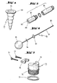
- the arrangement 1 for the distribution of pressurised fluid to areas of a seat unit 2 comprises essentially a first, fluid containing chamber 3 adaptable to the seat area 4 of the seat unit in such a way as to be adapted to receive, at least in part, the weight of the user of-the seat unit when sitting thereon.
- the chamber 3 is resilient and tends to recover and retain its normal volume when not subjected to the user's weight.
- this other chamber is formed by two chambers, namely one chamber 6 for supporting the user's back and another chamber 7 for supporting the said user's cervical area.
- Such chambers may be lined with soft covers and be coated with a upholstery having a certain degree of elasticity.
- Said chamber 3 communicates with said chamber 6 over a line 8 having two sections.8a and 8b. Furthermore, the chamber 3 communicates with the chamber 7 over a line 9 which also has sections 9a and 9b.
- valve means 50 Between each of the said pairs of sections there is inserted a valve means 50 to be described in further detail hereinafter. Said valve means is normally closed to fluid circulation in both directions.
- the arrangement also comprises first and second opening means 66 and 84 for each valve means, said opening means being controlled respectively by the button 81 and the knob 95.
- first and second opening means 66 and 84 for each valve means, said opening means being controlled respectively by the button 81 and the knob 95.
- the valve means 50 referred to above comprises a valve body 51 having a preferably cylindrical centre portion 52, a first end portion 53 and a second end portion 54. Said end portions 53, 54 are attached prefe bly to the centre portion 52 by means of a screw thread and are formed as caps which may be tapered as shown, 0 may have any other shape such as a rounded shape. Between the end portion 53 and the centre portion 52 there are held a rigid washer 55 and a resilient washer 56; the former is provided with a central orifice having a diameter generally identical to the internal diameter of the centre portion 52 and the latter has a central orifice 57 which forms the only communication between the interior of the centre portion 52 and the interior of the end portion 53.
- each end portion 53, 54 there is an access port 62, 63 respectively.
- the washers 56 and 59 are positioned between these ports and in this sense it is stated that the ports are substantially opposite each other.
- the ports are provided, respectively, with a neck portion 64, 65, the free end portion of which is provided with a saw-toothed formation for ease of connection to the valve means of communieation lines with the chambers.
- the first valve seat formed by the resilient washer 55, is associated with the first opening means or pusher 66 which is partly housed in the interior of a tubular member 67.
- This tubular member 67 is attached, preferably by a screw thread, to the end portion 53 of the valve body 51.
- a gasket (not shown).
- the tubular member 67 is provided with a shoulder 68, on which there seats the flange 69 of the open end 70 of a hood member 71 ( Figure 4) and this flange is applied against a washer 72, pressed on the opposite side thereof by the front end of a perforated plug 73, screwed into the tubular member.
- Said plug 73 is provided with a hexagonal portion 74 to facilitate the screwing thereof and an axial clamp-like projection 75 adapted to receive a second clamp 76, which may be adjustably attached to the projection 75 by screws 77 which may pass through the clamp 76 and screw into appropriate holes of the projection 75.
- the hood member 71 is resilient and elongate.and is formed preferably with folds or corrugations to allow for a greater elongation. It is, moreover, impermeable and consequently when mounted inside the tubular member 67 (with the flange 69 trapped between the washer 72 and the shoulder 68) it seals the tubular member 67.
- the first pusher means 66 is inserted through the perforation in the plug 73, said pusher means being formed by a cable 78 having preferably a ball end 79 and which, except for the end portions thereof, is inside a sheath 80.
- a cable 78 having preferably a ball end 79 and which, except for the end portions thereof, is inside a sheath 80.
- One of said end portions, as indicated hereinbefore, is inside the hood 71, whereas in the opposite end portion there is a button 81 which a spring 82 urges away from the end 83 of the sheath 80.
- the sheath is properly held between the axial clamp-like projection 75 and. the clamp 76 and the cable may be moved longitudinally relative to the sheath 80. Consequently, when pressing the button 8 1 , the cable moves longitudinally, whereby the ball end 79 extends the hood member 71 and the end of the latter crosses through the opening 57, to prevent the stopper 61 from seating against the washer 55 and maintaining therefore the communication between the interior of the valve body 51 and the port 62 open.
- the cable On releasing the button 81, the cable is retracted under the urging of the spring 82 and also under the resilience of the hood member 71.
- a seond opening means or pusher 84 housed partly in the tubular member 85 and associated with the washer 59 which forms the second valve seat.
- tubular member 85 is screwed to the end portion 54 of the valve body 51 and there is also a gasket (not shown).
- the tubular member 85 is also provided with a shoulder 86 and the flange 69 of the opening 70 of a further resilient, elongate hood member 71, as described above, is trapped between the shoulder 89 and a washer. To clamp said washer there is a threaded plug 87.
- This arrangement provides for a tight seal in a similar way as for the tubular member 67.
- the plug 87 is provided with an internal cavity 88 and the free end 89 thereof is provided with a radial slot 90.
- the pusher means 84 is formed by a rod 91 having a ball end 92, a disc 93 speared by the rod in the centre thereof, a pair of radial arms 94 and a control knob 95. Said rod may rotate relative to the tubular member 85.
- the rod 91 is positioned in the tubular member 85 in such a way that the end 92 thereof bears against the end of the hood member 71, the disc 93 is inside the plug 87 and the radial arms 94 are on the outside thereof.
- the device is installed on a seat unit such that each chamber is located in a corresponding area of the seat unit. In absence of any external force, the first chamber 3 is full of fluid. It is contemplated that the arrangement will have means allowing it to be removeably mounted to the seat unit. Said mounting means may be loops, strings, hoods, sheaths or other conventional means.
- valve means described above is particularly advantageous when installed in a seat unit usually used by the same person. In this case, it will be advantageous for the user to maintain the conditions in the chambers 6 and 7 always the same, whereby only occasionally will he have to operate the second opening means by way of the knob 95.
- valve means 50 which differs from the valve means 50 in that it does not have the washer 59 nor the second opening means 84.
- said simplified valve means when the overpressure caused by the user on the chamber 3 ceases, the stopper 61 moves away from the washer 56 on being urged by the pressure from the port 62. Since there is no other valve seat on which to bear, it does not interrupt the return communication between the chambers 6 and 7 and the chamber 3 and therefore the original conditions are effectively restored.
- Said simplified valve is very easy to produce from the valve means 50, it only being necessary to remove the resilient washer 59 and the tubular member 85 from the valve means 50 and replace the tubular member 85 by a plug sealing the port left open by removal of the said tubular member 85.
Landscapes
- Chairs For Special Purposes, Such As Reclining Chairs (AREA)
- Chair Legs, Seat Parts, And Backrests (AREA)
- Mattresses And Other Support Structures For Chairs And Beds (AREA)
- Massaging Devices (AREA)
- Chairs Characterized By Structure (AREA)
- Seats For Vehicles (AREA)
- Executing Machine-Instructions (AREA)
- Respiratory Apparatuses And Protective Means (AREA)
- Air Bags (AREA)
- Fluid-Driven Valves (AREA)
- Magnetically Actuated Valves (AREA)
- Compressor (AREA)
Priority Applications (1)
| Application Number | Priority Date | Filing Date | Title |
|---|---|---|---|
| AT83400817T ATE35612T1 (de) | 1982-05-06 | 1983-04-26 | Vorrichtung zum verteilen einer fluessigkeit unter druck zu einem sessel mit rueckenlehne. |
Applications Claiming Priority (4)
| Application Number | Priority Date | Filing Date | Title |
|---|---|---|---|
| ES264985 | 1982-05-06 | ||
| ES1982264985U ES264985Y (es) | 1982-05-06 | 1982-05-06 | Aparato distribuidor de presion graduable y equitativa para camaras hinchables emplazadas en sillas o sillones. |
| ES1983269906U ES269906Y (es) | 1982-05-06 | 1983-01-22 | Valvula. |
| ES269906 | 1983-01-22 |
Publications (3)
| Publication Number | Publication Date |
|---|---|
| EP0094281A2 true EP0094281A2 (de) | 1983-11-16 |
| EP0094281A3 EP0094281A3 (en) | 1985-03-06 |
| EP0094281B1 EP0094281B1 (de) | 1988-07-13 |
Family
ID=26155510
Family Applications (1)
| Application Number | Title | Priority Date | Filing Date |
|---|---|---|---|
| EP83400817A Expired EP0094281B1 (de) | 1982-05-06 | 1983-04-26 | Vorrichtung zum Verteilen einer Flüssigkeit unter Druck zu einem Sessel mit Rückenlehne |
Country Status (13)
| Country | Link |
|---|---|
| US (1) | US4514010A (de) |
| EP (1) | EP0094281B1 (de) |
| JP (1) | JPS58206704A (de) |
| AT (1) | ATE35612T1 (de) |
| AU (1) | AU555583B2 (de) |
| CA (1) | CA1216223A (de) |
| DK (1) | DK201583A (de) |
| ES (2) | ES264985Y (de) |
| FI (1) | FI76250C (de) |
| IL (1) | IL68470A (de) |
| NO (1) | NO163343C (de) |
| PT (1) | PT76638B (de) |
| ZA (1) | ZA833119B (de) |
Cited By (5)
| Publication number | Priority date | Publication date | Assignee | Title |
|---|---|---|---|---|
| US4555140A (en) * | 1984-02-23 | 1985-11-26 | Japan | Vehicle seat |
| GB2177849A (en) * | 1985-07-04 | 1987-01-28 | George Brian Todd | Push button control unit for valve or switch |
| US4890885A (en) * | 1987-11-24 | 1990-01-02 | Dr. Ing. H.C.F. Porsche Ag | Seat for a vehicle, aircraft or the like |
| GB2233893A (en) * | 1989-07-17 | 1991-01-23 | Boyd Saxon Moore | Contourable pneumatic cushion |
| WO2004050418A1 (de) * | 2002-12-05 | 2004-06-17 | Massoud Adib | Ventilsystem zum befüllen und entlüften von sitzpolstern, insbesondere in fahrzeugen, und steuerung zur fahrdynamischen ansteuerung eines solchen ventilsystems |
Families Citing this family (30)
| Publication number | Priority date | Publication date | Assignee | Title |
|---|---|---|---|---|
| US4629253A (en) * | 1986-01-15 | 1986-12-16 | Williams Theodore M | Seat occupant-activated underseat support air-cushion |
| US4720146A (en) * | 1986-08-28 | 1988-01-19 | General Motors Corporation | Vehicle seat headrest apparatus and method |
| US4693515A (en) * | 1986-10-27 | 1987-09-15 | Itt Corporation | Headrest for an automotive vehicle seat |
| US4738486A (en) * | 1986-12-12 | 1988-04-19 | Surber Keith V | Water-filled sitting furniture |
| US4840425A (en) * | 1987-04-21 | 1989-06-20 | Tush Cush, Inc. | Varying support cushioned seating assembly and method |
| US5098158A (en) * | 1989-08-17 | 1992-03-24 | Palarski Timothy D | Articulated relaxation chair |
| US4966413A (en) * | 1989-08-17 | 1990-10-30 | Palarski Timothy D | Articulated relaxation chair |
| US5137333A (en) * | 1990-01-25 | 1992-08-11 | Rolliture Corporation | Seat cushion |
| USD341053S (en) | 1992-06-08 | 1993-11-09 | Microcomputer Accessories, Inc. | Back pillow with contour adjustment means |
| US5564520A (en) * | 1994-06-20 | 1996-10-15 | Gt Development Corporation | Pneumatic seat rollover vent valve |
| US5547253A (en) * | 1994-08-11 | 1996-08-20 | Schwartz, Deceased; Edward M. | Sit/stand adjustable, tower chair |
| WO1996014783A1 (en) * | 1994-11-16 | 1996-05-23 | Cascade Designs, Inc. | Self-inflating modular seat insert |
| GB9508415D0 (en) * | 1995-04-25 | 1995-06-14 | Jeans Edward Lewis | Inflatable lifting device and control apparatus therefore |
| GB2316310B (en) * | 1995-06-09 | 1999-07-28 | Miller Herman Inc | Office chair and adjustable lumbar support therefor |
| US5590736A (en) * | 1995-09-08 | 1997-01-07 | Gt Development Corporation | Vehicle pneumatic seat rollover safety vent valve |
| US5738406A (en) * | 1996-09-30 | 1998-04-14 | Deus; Janet Lee | Air, gel or water filled bicycle seat |
| US5782529A (en) * | 1997-02-20 | 1998-07-21 | Alliedsignal Inc. | Inflatable seat back |
| DE19856561C1 (de) * | 1998-12-08 | 2000-04-20 | Faure Bertrand Sitztech Gmbh | Sitz, insbesondere Kraftfahrzeugsitz |
| RU2150223C1 (ru) * | 1998-12-15 | 2000-06-10 | Мелвин Собел | Предмет мягкой мебели |
| US6220663B1 (en) * | 1999-04-13 | 2001-04-24 | Neutral Posture Ergonomics, Inc. | Pump assembly for a chair |
| US6234577B1 (en) * | 2000-05-08 | 2001-05-22 | Joke, Inc. | Chair |
| GB2370222A (en) * | 2000-12-19 | 2002-06-26 | Autoliv Dev | Vehicle seat accessory providing lumbar / pelvic / shoulder support induced by weight of sitting person |
| US6877812B2 (en) * | 2002-12-06 | 2005-04-12 | Neutral Posture, Inc. | Support for a seating device |
| US8033600B2 (en) * | 2007-05-29 | 2011-10-11 | Ergoair, Inc. | Seat system with shock- and vibration-reducing bladders |
| FR2916699B1 (fr) * | 2007-06-04 | 2010-01-29 | Peugeot Citroen Automobiles Sa | Siege de vehicule automobile. |
| DE102009016051A1 (de) * | 2009-04-02 | 2010-10-07 | Bayerische Motoren Werke Aktiengesellschaft | Verfahren zur Erzeugung einer Tragschale für einen Sitz |
| DE102009016050A1 (de) * | 2009-04-02 | 2010-10-07 | Bayerische Motoren Werke Aktiengesellschaft | Auflage für einen Sitz |
| US20150224899A1 (en) * | 2012-09-12 | 2015-08-13 | Premier Plastics, Inc. | Rotomolded seat |
| US20150151658A1 (en) * | 2013-12-02 | 2015-06-04 | Benjamin G. Burris | Adjustable seat cover |
| US10525854B2 (en) | 2018-01-02 | 2020-01-07 | Dowco, Inc. | Adjustable seat |
Family Cites Families (9)
| Publication number | Priority date | Publication date | Assignee | Title |
|---|---|---|---|---|
| DE1292978B (de) * | 1962-02-17 | 1969-04-17 | Rheinisches Metallwerk Gmbh | Rueckschlagventil mit zusaetzlicher Handbetaetigung |
| US3273851A (en) * | 1963-05-23 | 1966-09-20 | Cons Electrodynamics Corp | Ball valve having urging means acting normal thereto |
| GB1078808A (en) * | 1963-08-01 | 1967-08-09 | Harold William Jensen | Improvements in valve fittings for controlling the outflow of liquids from hose and other pipe lines |
| US3330598A (en) * | 1966-02-14 | 1967-07-11 | Whiteside George Harold | Pneumatic seat |
| US3661422A (en) * | 1970-07-20 | 1972-05-09 | Universal Oil Prod Co | Self-adjustment for body support cushion |
| US3652126A (en) * | 1970-08-31 | 1972-03-28 | Universal Oil Prod Co | Pneumatic adjustment system for seat back panel |
| BE793830A (fr) * | 1972-01-11 | 1973-05-02 | Recticel Nv | Appui, en particulier coussin et matelas, ainsique son application |
| US4078842A (en) * | 1976-05-13 | 1978-03-14 | Henry Chanoch Zur | Kit for inflatable full length body supporting seat |
| CA1053387A (en) * | 1977-12-02 | 1979-04-24 | John P. Bentley | Inflatable seat cushion and body support assembly |
-
1982
- 1982-05-06 ES ES1982264985U patent/ES264985Y/es not_active Expired
-
1983
- 1983-01-22 ES ES1983269906U patent/ES269906Y/es not_active Expired
- 1983-04-20 CA CA000426321A patent/CA1216223A/en not_active Expired
- 1983-04-21 US US06/487,054 patent/US4514010A/en not_active Expired - Fee Related
- 1983-04-22 IL IL68470A patent/IL68470A/xx unknown
- 1983-04-26 AT AT83400817T patent/ATE35612T1/de not_active IP Right Cessation
- 1983-04-26 EP EP83400817A patent/EP0094281B1/de not_active Expired
- 1983-05-02 JP JP58078126A patent/JPS58206704A/ja active Pending
- 1983-05-03 AU AU14164/83A patent/AU555583B2/en not_active Ceased
- 1983-05-03 ZA ZA833119A patent/ZA833119B/xx unknown
- 1983-05-04 PT PT76638A patent/PT76638B/pt unknown
- 1983-05-05 DK DK201583A patent/DK201583A/da not_active Application Discontinuation
- 1983-05-05 NO NO831602A patent/NO163343C/no unknown
- 1983-05-06 FI FI831560A patent/FI76250C/fi not_active IP Right Cessation
Cited By (8)
| Publication number | Priority date | Publication date | Assignee | Title |
|---|---|---|---|---|
| US4555140A (en) * | 1984-02-23 | 1985-11-26 | Japan | Vehicle seat |
| GB2177849A (en) * | 1985-07-04 | 1987-01-28 | George Brian Todd | Push button control unit for valve or switch |
| US4890885A (en) * | 1987-11-24 | 1990-01-02 | Dr. Ing. H.C.F. Porsche Ag | Seat for a vehicle, aircraft or the like |
| GB2233893A (en) * | 1989-07-17 | 1991-01-23 | Boyd Saxon Moore | Contourable pneumatic cushion |
| GB2233893B (en) * | 1989-07-17 | 1993-06-16 | Boyd Saxon Moore | Contourable pneumatic cushion |
| WO2004050418A1 (de) * | 2002-12-05 | 2004-06-17 | Massoud Adib | Ventilsystem zum befüllen und entlüften von sitzpolstern, insbesondere in fahrzeugen, und steuerung zur fahrdynamischen ansteuerung eines solchen ventilsystems |
| DE10257117A1 (de) * | 2002-12-05 | 2004-07-15 | Massoud Adib | Ventilsystem zum Befüllen und Entlüften von Sitzpolstern, insbesondere in Fahrzeugen |
| DE10257117B4 (de) * | 2002-12-05 | 2004-11-04 | Massoud Adib | Ventilsystem zum Befüllen und Entlüften von Sitzpolstern, insbesondere in Fahrzeugen |
Also Published As
| Publication number | Publication date |
|---|---|
| NO163343B (no) | 1990-01-29 |
| ES269906Y (es) | 1984-01-16 |
| NO163343C (no) | 1990-05-09 |
| AU1416483A (en) | 1983-11-10 |
| ATE35612T1 (de) | 1988-07-15 |
| ES264985Y (es) | 1983-06-16 |
| EP0094281B1 (de) | 1988-07-13 |
| IL68470A (en) | 1986-03-31 |
| ES264985U (es) | 1983-01-01 |
| US4514010A (en) | 1985-04-30 |
| IL68470A0 (en) | 1983-07-31 |
| CA1216223A (en) | 1987-01-06 |
| FI76250B (fi) | 1988-06-30 |
| FI831560L (fi) | 1983-11-07 |
| DK201583D0 (da) | 1983-05-05 |
| AU555583B2 (en) | 1986-10-02 |
| FI831560A0 (fi) | 1983-05-06 |
| ZA833119B (en) | 1984-01-25 |
| JPS58206704A (ja) | 1983-12-02 |
| DK201583A (da) | 1983-11-07 |
| ES269906U (es) | 1983-07-01 |
| FI76250C (fi) | 1988-10-10 |
| PT76638A (en) | 1983-06-01 |
| PT76638B (en) | 1986-03-12 |
| EP0094281A3 (en) | 1985-03-06 |
| NO831602L (no) | 1983-11-07 |
Similar Documents
| Publication | Publication Date | Title |
|---|---|---|
| US4514010A (en) | Arrangement for the distribution of pressurized fluid to a seat unit having a backrest | |
| US3769982A (en) | Physiological drainage system with closure means responsive to downstream suction | |
| EP0069410A1 (de) | Stuhl | |
| US8739338B2 (en) | Inflatable cushion valve and attachment apparatus | |
| WO2004028307A1 (en) | Valve for zoned cellular cushion | |
| DK162453B (da) | Lodret indstillelig vandhane; isaer til en koekkenvask | |
| SE433968B (sv) | Omkopplingsventil for sanitetsarmaturer | |
| AU684734B2 (en) | Temperature responsive, pilot operated line valve with shapememory alloy actuator | |
| GB2026315A (en) | Cushions and mattresses | |
| US3661422A (en) | Self-adjustment for body support cushion | |
| US5279001A (en) | Toilet seat bidet assembly | |
| US2504257A (en) | Cleansing nozzle attachment for toilet bowls | |
| US20040082900A1 (en) | Proportional control device for a hydrocephalus shunt | |
| US2212607A (en) | Diaphragm and pressure operated valve | |
| US2600554A (en) | Sprinkler | |
| US6874173B2 (en) | Bidet device | |
| DE2905401A1 (de) | Bedarfs-einatmungsventil | |
| KR200270426Y1 (ko) | 의자 등받이의 각도 조절장치 | |
| WO2007105959A1 (en) | Chair with adjustable back support | |
| EP1536076A1 (de) | Sanitäres Reinigungsgerät | |
| DE19532302A1 (de) | Aufblasbares Lordosepolster für die Rückenlehne eines Dauergebrauchssitzes | |
| JPH0338436A (ja) | 車両用座席 | |
| KR200261039Y1 (ko) | 변기카바 좌판 타임열림장치 | |
| JPH0381165B2 (de) | ||
| KR920005913Y1 (ko) | 차량용 의자 팔걸이 장치 |
Legal Events
| Date | Code | Title | Description |
|---|---|---|---|
| PUAI | Public reference made under article 153(3) epc to a published international application that has entered the european phase |
Free format text: ORIGINAL CODE: 0009012 |
|
| AK | Designated contracting states |
Designated state(s): AT BE CH DE FR GB IT LI NL SE |
|
| PUAL | Search report despatched |
Free format text: ORIGINAL CODE: 0009013 |
|
| AK | Designated contracting states |
Designated state(s): AT BE CH DE FR GB IT LI NL SE |
|
| 17P | Request for examination filed |
Effective date: 19850629 |
|
| 17Q | First examination report despatched |
Effective date: 19860507 |
|
| GRAA | (expected) grant |
Free format text: ORIGINAL CODE: 0009210 |
|
| AK | Designated contracting states |
Kind code of ref document: B1 Designated state(s): AT BE CH DE FR GB IT LI NL SE |
|
| REF | Corresponds to: |
Ref document number: 35612 Country of ref document: AT Date of ref document: 19880715 Kind code of ref document: T |
|
| REF | Corresponds to: |
Ref document number: 3377328 Country of ref document: DE Date of ref document: 19880818 |
|
| ET | Fr: translation filed | ||
| ITF | It: translation for a ep patent filed | ||
| PLBE | No opposition filed within time limit |
Free format text: ORIGINAL CODE: 0009261 |
|
| STAA | Information on the status of an ep patent application or granted ep patent |
Free format text: STATUS: NO OPPOSITION FILED WITHIN TIME LIMIT |
|
| 26N | No opposition filed | ||
| PGFP | Annual fee paid to national office [announced via postgrant information from national office to epo] |
Ref country code: CH Payment date: 19910411 Year of fee payment: 9 |
|
| PGFP | Annual fee paid to national office [announced via postgrant information from national office to epo] |
Ref country code: SE Payment date: 19910417 Year of fee payment: 9 |
|
| PGFP | Annual fee paid to national office [announced via postgrant information from national office to epo] |
Ref country code: BE Payment date: 19910424 Year of fee payment: 9 |
|
| ITTA | It: last paid annual fee | ||
| PGFP | Annual fee paid to national office [announced via postgrant information from national office to epo] |
Ref country code: AT Payment date: 19910430 Year of fee payment: 9 Ref country code: NL Payment date: 19910430 Year of fee payment: 9 |
|
| PGFP | Annual fee paid to national office [announced via postgrant information from national office to epo] |
Ref country code: FR Payment date: 19920330 Year of fee payment: 10 |
|
| PGFP | Annual fee paid to national office [announced via postgrant information from national office to epo] |
Ref country code: DE Payment date: 19920423 Year of fee payment: 10 |
|
| PG25 | Lapsed in a contracting state [announced via postgrant information from national office to epo] |
Ref country code: AT Effective date: 19920426 |
|
| PG25 | Lapsed in a contracting state [announced via postgrant information from national office to epo] |
Ref country code: SE Effective date: 19920427 |
|
| PG25 | Lapsed in a contracting state [announced via postgrant information from national office to epo] |
Ref country code: LI Effective date: 19920430 Ref country code: BE Effective date: 19920430 Ref country code: CH Effective date: 19920430 |
|
| PGFP | Annual fee paid to national office [announced via postgrant information from national office to epo] |
Ref country code: GB Payment date: 19920812 Year of fee payment: 10 |
|
| BERE | Be: lapsed |
Owner name: SABATER GONZALEZ BUENAVENTURA Effective date: 19920430 |
|
| PG25 | Lapsed in a contracting state [announced via postgrant information from national office to epo] |
Ref country code: NL Effective date: 19921101 |
|
| NLV4 | Nl: lapsed or anulled due to non-payment of the annual fee | ||
| REG | Reference to a national code |
Ref country code: CH Ref legal event code: PL |
|
| PG25 | Lapsed in a contracting state [announced via postgrant information from national office to epo] |
Ref country code: GB Effective date: 19930426 |
|
| GBPC | Gb: european patent ceased through non-payment of renewal fee |
Effective date: 19930426 |
|
| PG25 | Lapsed in a contracting state [announced via postgrant information from national office to epo] |
Ref country code: FR Effective date: 19931229 |
|
| PG25 | Lapsed in a contracting state [announced via postgrant information from national office to epo] |
Ref country code: DE Effective date: 19940101 |
|
| REG | Reference to a national code |
Ref country code: FR Ref legal event code: ST |
|
| EUG | Se: european patent has lapsed |
Ref document number: 83400817.9 Effective date: 19921108 |