EP0094327B1 - Isolierputzträger, Anwendung für die Bildung von Isolierkörpern und Verfahren zum Herstellen eines solchen Körpers - Google Patents
Isolierputzträger, Anwendung für die Bildung von Isolierkörpern und Verfahren zum Herstellen eines solchen Körpers Download PDFInfo
- Publication number
- EP0094327B1 EP0094327B1 EP83400975A EP83400975A EP0094327B1 EP 0094327 B1 EP0094327 B1 EP 0094327B1 EP 83400975 A EP83400975 A EP 83400975A EP 83400975 A EP83400975 A EP 83400975A EP 0094327 B1 EP0094327 B1 EP 0094327B1
- Authority
- EP
- European Patent Office
- Prior art keywords
- insulating
- substrate
- insulating support
- coating
- support plate
- Prior art date
- Legal status (The legal status is an assumption and is not a legal conclusion. Google has not performed a legal analysis and makes no representation as to the accuracy of the status listed.)
- Expired
Links
- 238000000034 method Methods 0.000 title claims description 5
- 239000011505 plaster Substances 0.000 title description 19
- 238000009413 insulation Methods 0.000 title description 8
- 239000011248 coating agent Substances 0.000 claims abstract description 26
- 238000000576 coating method Methods 0.000 claims abstract description 26
- 239000000758 substrate Substances 0.000 claims abstract description 20
- 238000004873 anchoring Methods 0.000 claims abstract description 10
- 239000004570 mortar (masonry) Substances 0.000 claims description 14
- 239000000463 material Substances 0.000 claims description 8
- 239000011230 binding agent Substances 0.000 claims description 5
- 239000004794 expanded polystyrene Substances 0.000 claims description 4
- 239000004033 plastic Substances 0.000 claims description 4
- 229920003023 plastic Polymers 0.000 claims description 4
- 238000004519 manufacturing process Methods 0.000 claims description 3
- 238000004026 adhesive bonding Methods 0.000 claims description 2
- VEXZGXHMUGYJMC-UHFFFAOYSA-M Chloride anion Chemical compound [Cl-] VEXZGXHMUGYJMC-UHFFFAOYSA-M 0.000 claims 1
- 239000000945 filler Substances 0.000 claims 1
- 210000002445 nipple Anatomy 0.000 claims 1
- 238000010276 construction Methods 0.000 description 3
- 239000011810 insulating material Substances 0.000 description 3
- 239000000654 additive Substances 0.000 description 2
- 238000005336 cracking Methods 0.000 description 2
- 230000032798 delamination Effects 0.000 description 2
- 239000012634 fragment Substances 0.000 description 2
- 238000002955 isolation Methods 0.000 description 2
- 239000002184 metal Substances 0.000 description 2
- 239000012764 mineral filler Substances 0.000 description 2
- 230000035515 penetration Effects 0.000 description 2
- XLYOFNOQVPJJNP-UHFFFAOYSA-N water Substances O XLYOFNOQVPJJNP-UHFFFAOYSA-N 0.000 description 2
- XUMBMVFBXHLACL-UHFFFAOYSA-N Melanin Natural products O=C1C(=O)C(C2=CNC3=C(C(C(=O)C4=C32)=O)C)=C2C4=CNC2=C1C XUMBMVFBXHLACL-UHFFFAOYSA-N 0.000 description 1
- 229920001807 Urea-formaldehyde Polymers 0.000 description 1
- 230000000996 additive effect Effects 0.000 description 1
- 239000004568 cement Substances 0.000 description 1
- 238000005253 cladding Methods 0.000 description 1
- 230000001427 coherent effect Effects 0.000 description 1
- 150000001875 compounds Chemical class 0.000 description 1
- 238000005260 corrosion Methods 0.000 description 1
- 230000007797 corrosion Effects 0.000 description 1
- 238000009792 diffusion process Methods 0.000 description 1
- 238000009434 installation Methods 0.000 description 1
- -1 melanin compound Chemical class 0.000 description 1
- 239000000203 mixture Substances 0.000 description 1
- 238000000465 moulding Methods 0.000 description 1
- 239000010451 perlite Substances 0.000 description 1
- 235000019362 perlite Nutrition 0.000 description 1
- ODGAOXROABLFNM-UHFFFAOYSA-N polynoxylin Chemical compound O=C.NC(N)=O ODGAOXROABLFNM-UHFFFAOYSA-N 0.000 description 1
- 229920002635 polyurethane Polymers 0.000 description 1
- 239000004814 polyurethane Substances 0.000 description 1
- 229920000915 polyvinyl chloride Polymers 0.000 description 1
- 239000004800 polyvinyl chloride Substances 0.000 description 1
- 230000001681 protective effect Effects 0.000 description 1
- 239000008262 pumice Substances 0.000 description 1
- 238000009877 rendering Methods 0.000 description 1
- 238000007493 shaping process Methods 0.000 description 1
- 239000007921 spray Substances 0.000 description 1
- 238000005507 spraying Methods 0.000 description 1
- 239000004575 stone Substances 0.000 description 1
Images

Classifications
-
- E—FIXED CONSTRUCTIONS
- E04—BUILDING
- E04F—FINISHING WORK ON BUILDINGS, e.g. STAIRS, FLOORS
- E04F13/00—Coverings or linings, e.g. for walls or ceilings
- E04F13/02—Coverings or linings, e.g. for walls or ceilings of plastic materials hardening after applying, e.g. plaster
- E04F13/04—Bases for plaster
Definitions
- the invention relates to insulating supports for plaster and finds a particularly important application in the constitution of insulating complexes making it possible to reduce the heat exchanges through the walls of a building.
- the invention also makes it possible to make constructions, by mounting the insulating supports between load-bearing structures before applying the coating.
- an insulating panel is bonded to the substrate to be insulated which receives a patching compound in which a mesh is included. Then we spray a finishing plaster.
- the implementation of this process is simple, but gives a heterogeneous layer modifying the gas exchanges of the substrate.
- the present invention aims to provide attachment panels applicable to the constitution of thermal insulating complexes, responding better than those previously known to the requirements of practice, in particular in that it allows for high insulation, is implemented easy and of an acceptable cost price, and gives rise to corrosion-resistant complexes with very high adhesion of the coating to the support and to the substrate, thereby rendering the risks of cracking and delamination minimal.
- the invention provides an insulating support plate for plaster, comprising a trellis core, provided on at least one face with plaster anchoring means, characterized in that in the core are formed at regular intervals through perforations for receiving insulating plaster for bonding the substrate and the support.
- the perforations advantageously have a convergent-divergent shape from one face to the other to help the penetration of the coating during its projection and to improve the attachment to the support.
- the volume of material of the insulating support represents at least two thirds of the total volume including the voids.
- the core advantageously comprises, on the face intended to be fixed against the substrate to be insulated, anchoring means such as grooves around the perforations.
- a mesh grid can be placed on the support plate to further increase the adhesion of the plaster. This will generally consist of a mixture of hydraulic binder, expanded plastic material and insulating mineral filler, as well as lightening additive.
- the core will, as a rule, be made of expanded plastic material compatible with the coating.
- the support plate will generally be delivered in panels of a size compatible with current means of transport and handling: in practice, we can envisage the manufacture of panels whose surface ranges from 0.25 to 4 m 2. To ensure appreciable isolation , the thickness of the core must be at least 50 mm. It is generally unnecessary to exceed a thickness of 200 mm.
- the perforations will be distributed according to a regular network. We can consider a square mesh network, but it appeared preferable to use a triangular network in most cases.
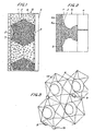
- the insulating complex 8 shown in FIG. 1 on a substrate 4 which will be assumed to be a building wall, either in restoration or in new work, comprises a support 1 made of insulating material, constituting a core.
- perforations 5 which, in the embodiment of FIG. 1, have a bitronconical shape so as to converge from the two faces. This geometry is however not essential and other forms are possible, provided that good penetration of the coating and satisfactory connection of the coating with the substrate 4.
- the face of the support 1 intended to bear against the substrate comprises means 3 for anchoring to the substrate, represented in the form of grooves.
- the face of the support 1 intended to receive the plaster has plaster anchoring means adding to the perforations 5.
- these anchoring means 2 are represented in the form of a cavity.
- the thickness of the insulating support 1 and the dimension of the perforations may vary, in particular as a function of the insulation to be produced. In the case where the perforations are distributed along a triangular network, a spacing between adjacent perforations of the order of one and a half times the diameter of the hole gives satisfactory results. We will deviate from this value if we use another type of network, for example an octagonal network combined with a square network.
- the insulating support 1 will generally be made by molding or shaping rigid or flexible, micro or macro-cellular heat-insulating materials, the proportion of closed cells of which is very high.
- the mechanical resistance of the material must obviously be compatible with the binder used and the fire resistance criteria must meet the standards in force. Expanded polystyrene will generally be a good choice.
- the support can be manufactured in the form of a rectangular panel, for example 0.50 m wide and 3 m long.
- the support is coated with a grid 7, for example made of metal wire, intended to further increase the attachment.
- the insulating mesh formed by the support 1 is then filled and covered, generally by spraying, with an insulating coating 6.
- the converging shape of the perforations guides the coating and facilitates the filling of the perforations and good adhesion with the substrate. Still in the case indicated in FIG. 1, the amount of coating applied is sufficient to allow a protection thickness which may be from 2 to 6 cm to remain above the support 1 or the grid 7.
- the mortar 6a may have one of any usual constitutions in construction, for example a poor mortar (at 120-350 kg per m 3 of binder) containing aggregates constituted by expanded polystyrene, insulating mineral fillers (for example stone- crushed pumice, dusted 1.5 to 3.5 mm or crushed raw perlite) and additives such as soluble silicas and air entrainers to lighten the mortar.
- the finishing plaster 6b will be chosen according to the local conditions of use and to protect the internal part of the complex 8.
- the manufacture of the insulating complex 8 is very simple: the insulating support panels 1 are first fixed to the substrate, for example by nailing or by gluing, possibly after stripping of the substrate as in the case of the installation of a traditional coating. .
- a base can be provided to avoid lowering the insulating supports to the ground. The panels can be cut to make corner returns.
- the mortar 6a is then sprayed, first in filling and then to form a thin layer covering the entire support 1. Locating pins 9 can be provided on the support 1 to allow easy equalization of the mortar 6a. Finishing plaster 6b is finally applied, in the traditional way.
- FIG. 3 and 4 show more precisely a particularly advantageous shape of the perforations 5.
- These perforations comprise a substantially cylindrical central zone 10 which is connected by a shoulder to a frustoconical zone 11 on the internal side.
- the internal side anchoring means consist of annular grooves 3 surrounding the perforations.
- the perforation comprises a frustoconical part 12 which is connected to a very flared part with flat sides 13. These flat sides 13 appear better in FIG. 5, which also shows the locations 14 for the action of release punches.
- the support plates according to the invention can also be used to form a filling in load-bearing structures, in particular in prefabricated constructions.
- the supports and the structural elements receive the heat-insulating coating on the outside and receive on the inside a finishing coating, such as plaster.
- a coherent assembly is formed, ensuring high thermal and sound insulation, having satisfactory mechanical strength, and which, moreover, simultaneously makes it possible to obtain impermeability to high water projections and good diffusion of water vapor, due to the presence of the mortar in contact with the wall.
- the multiplicity of plaster fixing points with the wall and the compatibility of the expansion coefficients also avoid the risks of cracking and delamination.
Landscapes
- Engineering & Computer Science (AREA)
- Architecture (AREA)
- Civil Engineering (AREA)
- Structural Engineering (AREA)
- Building Environments (AREA)
- Medicines Containing Material From Animals Or Micro-Organisms (AREA)
- Glass Compositions (AREA)
- Laminated Bodies (AREA)
- Investigation Of Foundation Soil And Reinforcement Of Foundation Soil By Compacting Or Drainage (AREA)
- Insulating Bodies (AREA)
- Catching Or Destruction (AREA)
- Finishing Walls (AREA)
Claims (10)
Priority Applications (1)
| Application Number | Priority Date | Filing Date | Title |
|---|---|---|---|
| AT83400975T ATE16297T1 (de) | 1982-05-12 | 1983-05-13 | Isolierputztraeger, anwendung fuer die bildung von isolierkoerpern und verfahren zum herstellen eines solchen koerpers. |
Applications Claiming Priority (2)
| Application Number | Priority Date | Filing Date | Title |
|---|---|---|---|
| FR8208221A FR2526828B1 (fr) | 1982-05-12 | 1982-05-12 | Support isolant pour enduit isolant, isolation ainsi obtenue, element isolant de structure, batiments ainsi equipes et procede de fabrication |
| FR8208221 | 1982-05-12 |
Publications (2)
| Publication Number | Publication Date |
|---|---|
| EP0094327A1 EP0094327A1 (de) | 1983-11-16 |
| EP0094327B1 true EP0094327B1 (de) | 1985-10-30 |
Family
ID=9273941
Family Applications (1)
| Application Number | Title | Priority Date | Filing Date |
|---|---|---|---|
| EP83400975A Expired EP0094327B1 (de) | 1982-05-12 | 1983-05-13 | Isolierputzträger, Anwendung für die Bildung von Isolierkörpern und Verfahren zum Herstellen eines solchen Körpers |
Country Status (4)
| Country | Link |
|---|---|
| EP (1) | EP0094327B1 (de) |
| AT (1) | ATE16297T1 (de) |
| DE (1) | DE3361109D1 (de) |
| FR (1) | FR2526828B1 (de) |
Families Citing this family (1)
| Publication number | Priority date | Publication date | Assignee | Title |
|---|---|---|---|---|
| GB2249564A (en) * | 1990-11-09 | 1992-05-13 | Medway Trading Limited | Cavity wall lintel |
Family Cites Families (7)
| Publication number | Priority date | Publication date | Assignee | Title |
|---|---|---|---|---|
| US1496207A (en) * | 1923-11-08 | 1924-06-03 | Carabillo Nicholas | Lathing |
| US1778145A (en) * | 1926-03-15 | 1930-10-14 | Willard J Mason | Plaster board |
| US2071454A (en) * | 1934-07-09 | 1937-02-23 | Reynolds Metals Co | Insulating lath material |
| GB483273A (en) * | 1936-10-10 | 1938-04-11 | Arthur Samuel John | Improved material for use as lathing and reinforcement in building constructions andin concrete structures such as road foundations |
| US2455016A (en) * | 1944-04-11 | 1948-11-30 | George A Buttress | Lath board |
| DE1683518A1 (de) * | 1966-03-17 | 1969-09-18 | Walter Schnabel | Plattenfoermiger Putztraeger |
| DE2842879A1 (de) * | 1978-10-02 | 1980-04-17 | Wiehofsky Alfred | Bauplatte mit putztragender oberflaeche |
-
1982
- 1982-05-12 FR FR8208221A patent/FR2526828B1/fr not_active Expired
-
1983
- 1983-05-13 DE DE8383400975T patent/DE3361109D1/de not_active Expired
- 1983-05-13 EP EP83400975A patent/EP0094327B1/de not_active Expired
- 1983-05-13 AT AT83400975T patent/ATE16297T1/de active
Also Published As
| Publication number | Publication date |
|---|---|
| EP0094327A1 (de) | 1983-11-16 |
| ATE16297T1 (de) | 1985-11-15 |
| FR2526828B1 (fr) | 1986-07-18 |
| DE3361109D1 (en) | 1985-12-05 |
| FR2526828A1 (fr) | 1983-11-18 |
Similar Documents
| Publication | Publication Date | Title |
|---|---|---|
| EP2295666B1 (de) | Herstellungsverfahren für dämmpaneele und solch ein dämmpaneel | |
| EP2633133B1 (de) | Ineinandergreifender baustein aus einer anordnung von abschnitten aus zusammengefügten und in einem umspritzten kunststoff verkapselten feststoffen | |
| EP2920377B1 (de) | Verfahren zum errichten eines gebäudes mit starker wärmedämmung und in diesem verfahren errichtetes gebäude | |
| FR2996572A1 (fr) | Poutrelle structuree et element modulaire de construction realise avec cette poutrelle | |
| CH654614A5 (en) | Precast reinforced-concrete wall or floor element with built-in insulation | |
| FR3017889A1 (fr) | Panneau de construction composite | |
| EP0094327B1 (de) | Isolierputzträger, Anwendung für die Bildung von Isolierkörpern und Verfahren zum Herstellen eines solchen Körpers | |
| EP2725162A1 (de) | Baustein aus einem Porenbetonkörper in Plastikhülle | |
| FR2552477A1 (fr) | Panneau modulaire pour planchers sureleves | |
| WO1984003318A1 (fr) | Mur de construction composite et isolant | |
| EP2473684B1 (de) | Gebäudewand und verfahren zur herstellung der wand | |
| FR2583089A1 (fr) | Panneau composite de construction | |
| FR2591147A1 (fr) | Nouveau materiau composite stratifie rigide | |
| EP0131671B1 (de) | Verfahren für die Konstruktion von Häusern aus Holz | |
| EP1295999B1 (de) | Verbesserte Halterung eines Isolierelementes an einem Träger | |
| FR2612540A1 (fr) | Panneau composite pour cloison et son procede de fabrication | |
| FR2834241A1 (fr) | Panneau multicouche, procede de fabrication et utilisations d'un tel panneau | |
| FR2499615A1 (fr) | Plaque composite d'habillage et d'isolation internes pour batiment | |
| EP0135240A2 (de) | Selbsttragende Platte für einen doppelten Fussboden | |
| FR2953872A1 (fr) | Panneau monobloc prefabrique multi-couche | |
| FR2990707A1 (fr) | Bloc de construction isolant | |
| FR2485590A1 (fr) | Perfectionnements apportes aux panneaux de doublage isolant notamment pour murs, cloisons, planchers et plafonds | |
| FR2494749A1 (fr) | Procede de construction de murs de batiments a colombage | |
| CN114086705A (zh) | 一种高强度加固型幕墙用铝单板及其制造工艺 | |
| FR3027615A1 (fr) | Bloc de construction pour la realisation d'une structure maconnee |
Legal Events
| Date | Code | Title | Description |
|---|---|---|---|
| PUAI | Public reference made under article 153(3) epc to a published international application that has entered the european phase |
Free format text: ORIGINAL CODE: 0009012 |
|
| AK | Designated contracting states |
Designated state(s): AT BE CH DE GB IT LI LU NL |
|
| 17P | Request for examination filed |
Effective date: 19840512 |
|
| GRAA | (expected) grant |
Free format text: ORIGINAL CODE: 0009210 |
|
| ITF | It: translation for a ep patent filed | ||
| AK | Designated contracting states |
Designated state(s): AT BE CH DE GB IT LI LU NL |
|
| REF | Corresponds to: |
Ref document number: 16297 Country of ref document: AT Date of ref document: 19851115 Kind code of ref document: T |
|
| REF | Corresponds to: |
Ref document number: 3361109 Country of ref document: DE Date of ref document: 19851205 |
|
| PG25 | Lapsed in a contracting state [announced via postgrant information from national office to epo] |
Ref country code: LU Free format text: LAPSE BECAUSE OF NON-PAYMENT OF DUE FEES Effective date: 19860531 |
|
| PLBE | No opposition filed within time limit |
Free format text: ORIGINAL CODE: 0009261 |
|
| STAA | Information on the status of an ep patent application or granted ep patent |
Free format text: STATUS: NO OPPOSITION FILED WITHIN TIME LIMIT |
|
| 26N | No opposition filed | ||
| PGFP | Annual fee paid to national office [announced via postgrant information from national office to epo] |
Ref country code: LU Payment date: 19900528 Year of fee payment: 8 |
|
| PGFP | Annual fee paid to national office [announced via postgrant information from national office to epo] |
Ref country code: GB Payment date: 19900529 Year of fee payment: 8 |
|
| PGFP | Annual fee paid to national office [announced via postgrant information from national office to epo] |
Ref country code: NL Payment date: 19900531 Year of fee payment: 8 |
|
| PGFP | Annual fee paid to national office [announced via postgrant information from national office to epo] |
Ref country code: BE Payment date: 19900712 Year of fee payment: 8 |
|
| PG25 | Lapsed in a contracting state [announced via postgrant information from national office to epo] |
Ref country code: GB Effective date: 19910513 |
|
| PG25 | Lapsed in a contracting state [announced via postgrant information from national office to epo] |
Ref country code: BE Effective date: 19910531 |
|
| BERE | Be: lapsed |
Owner name: PERROUDON MICHEL GASTON Effective date: 19910531 Owner name: RIZZA MICHEL ALFRED Effective date: 19910531 |
|
| PG25 | Lapsed in a contracting state [announced via postgrant information from national office to epo] |
Ref country code: NL Effective date: 19911201 |
|
| GBPC | Gb: european patent ceased through non-payment of renewal fee | ||
| NLV4 | Nl: lapsed or anulled due to non-payment of the annual fee | ||
| ITTA | It: last paid annual fee | ||
| PGFP | Annual fee paid to national office [announced via postgrant information from national office to epo] |
Ref country code: AT Payment date: 19970530 Year of fee payment: 15 |
|
| PG25 | Lapsed in a contracting state [announced via postgrant information from national office to epo] |
Ref country code: AT Free format text: LAPSE BECAUSE OF NON-PAYMENT OF DUE FEES Effective date: 19980513 |
|
| PGFP | Annual fee paid to national office [announced via postgrant information from national office to epo] |
Ref country code: DE Payment date: 19990514 Year of fee payment: 17 |
|
| PGFP | Annual fee paid to national office [announced via postgrant information from national office to epo] |
Ref country code: CH Payment date: 19990521 Year of fee payment: 17 |
|
| PG25 | Lapsed in a contracting state [announced via postgrant information from national office to epo] |
Ref country code: LI Free format text: LAPSE BECAUSE OF NON-PAYMENT OF DUE FEES Effective date: 20000531 Ref country code: CH Free format text: LAPSE BECAUSE OF NON-PAYMENT OF DUE FEES Effective date: 20000531 |
|
| REG | Reference to a national code |
Ref country code: CH Ref legal event code: PL |
|
| PG25 | Lapsed in a contracting state [announced via postgrant information from national office to epo] |
Ref country code: DE Free format text: LAPSE BECAUSE OF NON-PAYMENT OF DUE FEES Effective date: 20010301 |