EP0094454A2 - Starres Befestigungsglied mit thermischer Selbstspannung - Google Patents
Starres Befestigungsglied mit thermischer Selbstspannung Download PDFInfo
- Publication number
- EP0094454A2 EP0094454A2 EP82111862A EP82111862A EP0094454A2 EP 0094454 A2 EP0094454 A2 EP 0094454A2 EP 82111862 A EP82111862 A EP 82111862A EP 82111862 A EP82111862 A EP 82111862A EP 0094454 A2 EP0094454 A2 EP 0094454A2
- Authority
- EP
- European Patent Office
- Prior art keywords
- pipe
- equipment
- link
- support
- rigid
- Prior art date
- Legal status (The legal status is an assumption and is not a legal conclusion. Google has not performed a legal analysis and makes no representation as to the accuracy of the status listed.)
- Granted
Links
Images


Classifications
-
- F—MECHANICAL ENGINEERING; LIGHTING; HEATING; WEAPONS; BLASTING
- F16—ENGINEERING ELEMENTS AND UNITS; GENERAL MEASURES FOR PRODUCING AND MAINTAINING EFFECTIVE FUNCTIONING OF MACHINES OR INSTALLATIONS; THERMAL INSULATION IN GENERAL
- F16L—PIPES; JOINTS OR FITTINGS FOR PIPES; SUPPORTS FOR PIPES, CABLES OR PROTECTIVE TUBING; MEANS FOR THERMAL INSULATION IN GENERAL
- F16L3/00—Supports for pipes, cables or protective tubing, e.g. hangers, holders, clamps, cleats, clips, brackets
- F16L3/08—Supports for pipes, cables or protective tubing, e.g. hangers, holders, clamps, cleats, clips, brackets substantially surrounding the pipe, cable or protective tubing
-
- F—MECHANICAL ENGINEERING; LIGHTING; HEATING; WEAPONS; BLASTING
- F16—ENGINEERING ELEMENTS AND UNITS; GENERAL MEASURES FOR PRODUCING AND MAINTAINING EFFECTIVE FUNCTIONING OF MACHINES OR INSTALLATIONS; THERMAL INSULATION IN GENERAL
- F16L—PIPES; JOINTS OR FITTINGS FOR PIPES; SUPPORTS FOR PIPES, CABLES OR PROTECTIVE TUBING; MEANS FOR THERMAL INSULATION IN GENERAL
- F16L3/00—Supports for pipes, cables or protective tubing, e.g. hangers, holders, clamps, cleats, clips, brackets
- F16L3/16—Supports for pipes, cables or protective tubing, e.g. hangers, holders, clamps, cleats, clips, brackets with special provision allowing movement of the pipe
- F16L3/18—Supports for pipes, cables or protective tubing, e.g. hangers, holders, clamps, cleats, clips, brackets with special provision allowing movement of the pipe allowing movement in axial direction
-
- Y—GENERAL TAGGING OF NEW TECHNOLOGICAL DEVELOPMENTS; GENERAL TAGGING OF CROSS-SECTIONAL TECHNOLOGIES SPANNING OVER SEVERAL SECTIONS OF THE IPC; TECHNICAL SUBJECTS COVERED BY FORMER USPC CROSS-REFERENCE ART COLLECTIONS [XRACs] AND DIGESTS
- Y10—TECHNICAL SUBJECTS COVERED BY FORMER USPC
- Y10S—TECHNICAL SUBJECTS COVERED BY FORMER USPC CROSS-REFERENCE ART COLLECTIONS [XRACs] AND DIGESTS
- Y10S248/00—Supports
- Y10S248/901—Support having temperature or pressure responsive feature
Definitions
- This invention relates in general to a device for supporting and/or controlling movement of equipment, especially piping, subject to changes in position due to thermal expansion and contraction.
- Pipes are often supported by hangers and snubbers such that the pipe may move freely if movement is slow, but rapid movement of the pipe is resisted.
- the present invention resides in a support arrangement for a pipe connected to equipment at a predetermined point which is subject to position changes depending on the temperature of the equipment and the pipe, said support arrangement including rigid links pivotally connected to said pipe and to a support structure adjacent said pipe for supporting said pipe thereon, characterized in that the length and angular position of each link relative to said pipe is so selected that axial movement of said pipe will cause said links to apply stresses to said pipe so as to force said pipe into a shape which provides for relatively low stresses at said point of connection of said pipe to said equipment and avoids stress peaks throughout said pipe.
- a rigid-link pipe support consists of a rigid link pivotally joined at one end to the pipe and similarly joined at the other end to a stationary anchor. During pipe/equipment movement, the link may pivot at both points.
- the rigid link support is planned in advance of installation to use the forces and displacements generated by movement and dimensional changes in the pipe during pipe temperature changes to stress and/or pivot the rigid link such that the pipe is properly stressed and supported when at its long term operating temperature.
- the rigid link support does not merely accommodate thermal movement of the pipe, but utilizes such movement to regulate pipe stresses and to generate forces opposing further movement of the pipe.
- the rigid link support prevents pipe/equipment movement along the length of the link and opposes motion in other directions by forcing any such motion to include an additional directional component imposed by a push or pull by the link.
- Installation of the rigid link support can be planned such that the pipe/equipment is forced out of its natural free position at either or both operating and room temperatures, creating stress in and support for the pipe/equipment termed "springing".
- the rigid link support is particularly adaptable to steam stations and refrigeration apparatus since piping therein is normally operated at a constant, known, elevated or reduced temperature.
- the pipe support has a rigid link pivotally connected at one end to a pipe mount and pivotally connected at the opposite end to an anchor mount on a structure suitable as an anchor for the support of the pipe so that the length, and angle of installation of the link with respect to the pipe chosen at a room temperature are such that movement of the pipe due to thermal heatup or cooldown causes pivotal movement of the link so as to position the pipe in a manner to avoid stress peaks.
- the rigid link support may be installed with appropriate link length and angle with respect to the pipe such that pipe and link stresses exist at room temperature. This condition is called “RT sprung” herein.
- Figure 1 shows a pipe 1 at room temperature for which support is to be provided.
- Mounts 7 are shown installed to anchor 3 and pipe 1.
- Pins 4 are provided for attachment of a rigid link (not shown).
- FIG 3 shows the system in the configuration resulting from a thermal change of pipe 1 from room temperature to operating temperature.
- Pipe 1 has shifted in the direction of arrow 6 (in Figure 2) and has pivoted at pins 4, pushing pipe 1 downward by a distance equal to C, the length of link 2, less the distance b which is a side of a right triangle of which C is the hypotenuse as illustrated in Figure 2.
- Pipe 1 is also pushed down a small distance additionally due to any rigid link 2 thermal expansion (or, if link 2 is cooled during the thermal change which occurs to the operating temperature, this effect reduces the distance pipe 1 is pushed down).
- the change in rigid link 2 length is expressed as aAT where a is the coefficient of expansion (of link 2) and AT is the temperature change of link 2 from room temperature to the operating temperature, of link 2 (AT may be a positive or negative quantity.
- a is the coefficient of expansion (of link 2)
- AT is the temperature change of link 2 from room temperature to the operating temperature, of link 2 (AT may be a positive or negative quantity.
- the exact details of this calculation depends on the overall configuration involving the supports and the building as well as the temperature and expansion coefficients of the building, link, and mounts.) Pipe radial growth is not important when pipe 1 is supported as in Figure 3.
- pipe 1 is shown to be pushed down to a distance (D+6+C-b)(l+aAT) from anchor surface 3.
- the distance pipe 1 shifts (along arrow 6) for a specific AT is often a known quantity. This shift distance is represented by a dotted line 26 in Figure 1.
- Angle 14 (in Fig. 1) and link 2 length can be chosen such that the stress in link 2 and pipe 1 in the configuration shown in Figure 3 at the pipe 1 operating temperature is an acceptable and desired value.
- FIG. 1 The configuration depicted in Figures 1, 2, and 3 is appropriate to push pipe 1 further away from anchor surface 3 during heatup (or cooldown).
- the rigid link support system can also be arranged to pull pipe 1 closer to anchor surface 3 during heatup (or cooldown) as illustrated in Figures 4 and 5.
- Figure 4 shows an installed rigid link support 8 for a pipe 1 at room temperature; If pipe 1 is pulled upward somewhat by link 2 in Figure 4 it is RT sprung. Pipe 1 is known to move to the right in the direction of arrow 6 during a temperature change to the operating temperature (shown in Figure 5).
- a pipe or system of pipes may be supported by a plurality of rigid link supports, of the "push” variety (see Figures 1, 2, 3) and/or “pull” variety (see Figures 4, 5) or a combination of these with other types of pipe supports.
- Figure 6 illustrates a system designed to support pipe 1 with rigid link supports 8, and snubbers 9.
- Pipe 1 connects a pump 11 and a heat exchanger 12.
- Such a system can be planned prior to construction of the piping system with each rigid link support 8 providing push or pull needed at various locations such that the overall pipe is properly supported in the operating condition as well as during transient or short term operating conditions. Combination with other support types may be desired as these may serve special functions such as earthquake protection.
- Figure 7 is a graph which illustrates the use of multiple rigid link supports 8 to support the piping system shown in Figure 6.
- Pipe 1 is shown stretched out straight for purposes of this analysis along line 16 which also has pump 11 and heat exchanger 12 positions indicated.
- Snubbers 9 are omitted from Figure 7 since they provide a special service not relevant to this discussion.
- pipe 1 is a straight run of pipe between pump 11 and heat exchanger 12, the free vertical deflection position (with no supports installed) of pipe 1 at room temperature (line 17) is a horizontal, straight line.
- rigid link supports Rl, R2, R3, R4 With four rigid link supports (Rl, R2, R3, R4) installed, pipe 1 is RT sprung to the deflection from line 17 represented by line 19, the RT sprung deflection.
- the number, locations, and lengths of rigid link supports Rl, R2, R3, R4 are chosen to provide the RT sprung deflection of line 19 because, besides supporting pipe 1 at room temperature, these supports also position pipe 1 at the operating temperature along line 20 which is close to the free deflection line 18.
- Rigid link supports R1, R2, R3, and R4 are pulling pipe 1 upward, (from free position 18 to operating position 20) providing an operating temperature stress, defined as an "operating temperature sprung" or "OT sprung" condition, and providing pipe 1 with support in the Y direction (see coordinate axes in Figure 6).
- a similar graph could be made of the XZ plane which would be used as a means to pick locations, lengths, and numbers of rigid link supports for support of pipe 1 in that plane.
- FIG 8 shows pump 11 surrounded by a guard vessel 23. It is known that pipe support point 30 drops downward by one inch during heatup. It is desired to provide pipe 1 with vertical support at room temperature as well as after the one inch downward movement at operating temperature.
- link 2 and upper mount 7 on anchor 3 has a slot 22.
- the lower mount 10 fixed to the pipe may be elongated to provide convenient access to pipe 1.
- Link 2 is attached to mounts 7 and 10 with pins 4.
- FIG 8 the support is shown in an RT sprung condition (pipe pushed down).
- the stress due to the RT sprung condition is relieved and for an additional range of travel of pipe 1 downward, corresponding to a range of the heatup, no further push or pull is generated because pin 4 is freely movable in slot 22.
- Figure 10 shows the configuration after the pipe 1 has reached the temperature where pipe 1 movement downward caused pin 4 to reach the end of slot 22. Further heatup will generate stress to support pipe 1.
- the overall effect of slot 22 is to reduce the portion of the one inch downward travel of pipe 1 which is used to generate pipe elbow 29 stress.
- link 2 is perpendicular to pipe 1 when pipe 1 is at operating temperature wherein pipe 1 is under predetermined stress. It may well be desired however that link 2 at operating temperature would not yet have reached a 90° angle to pipe 1.
- Figure 11 shows an adjustable link support, using a mount 7 having bolts and nuts 24 permitting adjustment of the standoff distance to anchor surface 3.
- a primary use of rigid links will be to support piping in liquid metal fast breeder reactor (LMFBR) plants.
- LMFBR liquid metal fast breeder reactor
- Figure 12 is the conventional arrangement with snubbers 9 and snubber and hanger combination 37.
- Figures 14, 15, and 16 show the mechanics of this approach.
- Figure 14 shows unrestrained movement of points 39 and 34 by thermal expansion as the piping system is heated up to 470°C.
- Fig. 15 shows that by cold springing point 39 in the z direction 1 cm. of the 2 cm. it would normally move to when heated to 470°C and by cold spring in a point 34 in the x direction 2.8 cm. of the 5 cm. it would normally move to when heatd to 470°C the pipe will cause an elbow stress within a reasonable value.
- the stress range was higher with links (-2100 kg/cm 2 cold to +3100 kg/cm 2 hot) compared to the conventional design (0 cold to +30,000 psi hot). But, if there are not many cycles back down to room temperature, this may not be a significant handicap.
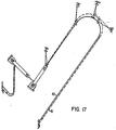
- Figure 17 is a composite of Figures 13, through 16 which shows how the pipe shifts from cold (curve 40) to hot (curve 41).
- stresses at the connecting point of the pipe to the equipment may be relatively low at operating temperature so that breaks are not likely to occur during operation.
- the piping is maintained by the solid links under stress so that vibrations are not likely to occur during earthquakes, for example.
Landscapes
- Engineering & Computer Science (AREA)
- General Engineering & Computer Science (AREA)
- Mechanical Engineering (AREA)
- Supports For Pipes And Cables (AREA)
Applications Claiming Priority (2)
| Application Number | Priority Date | Filing Date | Title |
|---|---|---|---|
| US06/378,447 US4483500A (en) | 1981-05-27 | 1982-05-14 | Piping support system for liquid-metal fast-breeder reactor |
| US378447 | 1982-05-14 |
Publications (3)
| Publication Number | Publication Date |
|---|---|
| EP0094454A2 true EP0094454A2 (de) | 1983-11-23 |
| EP0094454A3 EP0094454A3 (en) | 1984-07-11 |
| EP0094454B1 EP0094454B1 (de) | 1987-07-29 |
Family
ID=23493171
Family Applications (1)
| Application Number | Title | Priority Date | Filing Date |
|---|---|---|---|
| EP82111862A Expired EP0094454B1 (de) | 1982-05-14 | 1982-12-21 | Starres Befestigungsglied mit thermischer Selbstspannung |
Country Status (7)
| Country | Link |
|---|---|
| US (1) | US4483500A (de) |
| EP (1) | EP0094454B1 (de) |
| JP (1) | JPS58200883A (de) |
| KR (1) | KR840003344A (de) |
| DE (1) | DE3276876D1 (de) |
| ES (1) | ES518977A0 (de) |
| YU (1) | YU290082A (de) |
Cited By (1)
| Publication number | Priority date | Publication date | Assignee | Title |
|---|---|---|---|---|
| FR2564960A1 (fr) * | 1984-05-25 | 1985-11-29 | Novatome | Echangeur de chaleur pour le refroidissement d'un metal liquide par de l'air |
Families Citing this family (4)
| Publication number | Priority date | Publication date | Assignee | Title |
|---|---|---|---|---|
| JP4600842B2 (ja) * | 2008-06-10 | 2010-12-22 | 東京貿易機械株式会社 | 流体荷役装置支持構造 |
| JP6560860B2 (ja) * | 2013-12-25 | 2019-08-14 | 株式会社トクシン電気 | 配管制振システム |
| CN106151683B (zh) * | 2015-03-31 | 2019-03-08 | 德真电气株式会社 | 配管减振系统 |
| KR20160123013A (ko) * | 2015-04-15 | 2016-10-25 | 가부시키가이샤 도쿠신 덴키 | 배관 진동 제어 시스템 |
Family Cites Families (16)
| Publication number | Priority date | Publication date | Assignee | Title |
|---|---|---|---|---|
| GB594232A (en) * | 1945-01-09 | 1947-11-06 | George Oulianoff | Improvements in or relating to suspension devices for maintaining the alignment of pipes and other bodies subject to small axial movements |
| US1315890A (en) * | 1919-09-09 | Pipe-hanger | ||
| US1466292A (en) * | 1922-05-10 | 1923-08-28 | Gen Fire Extinguisher Co | Pipe-anchoring means |
| US2339565A (en) * | 1943-03-10 | 1944-01-18 | Abraham G Goldberg | Pipe hanger |
| US2707128A (en) * | 1951-01-05 | 1955-04-26 | Greenfield Company | Visor center bracket with aerial spanning foot |
| US2912198A (en) * | 1955-08-19 | 1959-11-10 | Int Harvester Co | Motor vehicle exhaust muffler support means |
| US3044739A (en) * | 1959-11-27 | 1962-07-17 | James W Attwood | Pipe supports |
| US3112909A (en) * | 1961-12-26 | 1963-12-03 | Bergen Pipesupport Corp | Support apparatus for piping and the like |
| US3288406A (en) * | 1965-11-22 | 1966-11-29 | George R Degen | Adjustable pipe support |
| US3493206A (en) * | 1968-04-25 | 1970-02-03 | Cabot Corp | Adjustable pipe hanger |
| US3539136A (en) * | 1969-03-13 | 1970-11-10 | Leonard S Suozzo | Thermo-mechanical multi-function support device |
| JPS53136724A (en) * | 1977-05-02 | 1978-11-29 | Nhk Spring Co Ltd | Supporting pole |
| US4194711A (en) * | 1978-01-09 | 1980-03-25 | Leroy Winton | Flexible sewer line support |
| US4299364A (en) * | 1978-08-07 | 1981-11-10 | General Signal Corporation | Insulating module including a heater element support |
| FR2472129A1 (fr) * | 1979-12-21 | 1981-06-26 | Framatome Sa | Dispositif de maintien d'une tuyauterie |
| US4309019A (en) * | 1980-11-03 | 1982-01-05 | Bloom Stephen R | Adjustable tailpipe hanger |
-
1982
- 1982-05-14 US US06/378,447 patent/US4483500A/en not_active Expired - Fee Related
- 1982-12-21 DE DE8282111862T patent/DE3276876D1/de not_active Expired
- 1982-12-21 EP EP82111862A patent/EP0094454B1/de not_active Expired
- 1982-12-28 JP JP57235013A patent/JPS58200883A/ja active Pending
- 1982-12-28 YU YU02900/82A patent/YU290082A/xx unknown
-
1983
- 1983-01-13 ES ES518977A patent/ES518977A0/es active Granted
- 1983-01-14 KR KR1019830000122A patent/KR840003344A/ko not_active Ceased
Cited By (2)
| Publication number | Priority date | Publication date | Assignee | Title |
|---|---|---|---|---|
| FR2564960A1 (fr) * | 1984-05-25 | 1985-11-29 | Novatome | Echangeur de chaleur pour le refroidissement d'un metal liquide par de l'air |
| EP0165840A1 (de) * | 1984-05-25 | 1985-12-27 | Novatome | Wärmetauscher zur Kühlung eines flüssigen Metalls durch Luft |
Also Published As
| Publication number | Publication date |
|---|---|
| YU290082A (en) | 1987-10-31 |
| ES8402408A1 (es) | 1984-01-16 |
| DE3276876D1 (en) | 1987-09-03 |
| KR840003344A (ko) | 1984-08-20 |
| JPS58200883A (ja) | 1983-11-22 |
| EP0094454A3 (en) | 1984-07-11 |
| ES518977A0 (es) | 1984-01-16 |
| EP0094454B1 (de) | 1987-07-29 |
| US4483500A (en) | 1984-11-20 |
Similar Documents
| Publication | Publication Date | Title |
|---|---|---|
| US4263964A (en) | Heat exchanger support system | |
| US3951108A (en) | Means for supporting a displaceable mass on a stationary frame | |
| US4134563A (en) | Pipe support | |
| JPH02290405A (ja) | 外殻部材の半径方向支持装置 | |
| EP0094454B1 (de) | Starres Befestigungsglied mit thermischer Selbstspannung | |
| US5342016A (en) | Device for supporting, on a fixed framework, a mass which is cantilevered out from a moving element | |
| EP0294639B1 (de) | Tieftemperaturhalterungssystem | |
| WO1993012367A1 (en) | Pipe restraint | |
| US5406791A (en) | Support apparatus for the exhaust pipe of an internal combustion engine | |
| US4832305A (en) | Equipment support system | |
| CN108986933B (zh) | 用于多容器系统的模块化支承装置 | |
| CN217653494U (zh) | 一种热力管道固定用抗震支架 | |
| AU2012203351B2 (en) | Solar boiler tube panel supports | |
| CN207651187U (zh) | 反应堆一回路及反应堆主设备滚动支承装置 | |
| CN216666717U (zh) | 带有水平位移补偿装置的弹簧吊架 | |
| CN222848805U (zh) | 一种弹性支撑与水平限位组合式支吊架及管道系统 | |
| CN108986932B (zh) | 用于多容器系统的模块化分层支承装置 | |
| KR100886886B1 (ko) | 초전도 cs 코일의 전치하중 구조물 및 전치하중 인가방법 | |
| EP0305171A1 (de) | Erdbebenstoppende Abstützung | |
| KR102332460B1 (ko) | 증기 발생기의 면진 시스템 | |
| US4239598A (en) | Nuclear reactor heat transport system component low friction support system | |
| CN221743448U (zh) | 一种全方位大位移补偿u型隔震金属软管 | |
| CN220102316U (zh) | 一种用于消防的抗震支架 | |
| JPH0653882U (ja) | 配管支持装置 | |
| JPH087208Y2 (ja) | バーナの支持装置 |
Legal Events
| Date | Code | Title | Description |
|---|---|---|---|
| PUAI | Public reference made under article 153(3) epc to a published international application that has entered the european phase |
Free format text: ORIGINAL CODE: 0009012 |
|
| AK | Designated contracting states |
Designated state(s): BE DE FR GB IT SE |
|
| PUAL | Search report despatched |
Free format text: ORIGINAL CODE: 0009013 |
|
| AK | Designated contracting states |
Designated state(s): BE DE FR GB IT SE |
|
| 17P | Request for examination filed |
Effective date: 19841231 |
|
| 17Q | First examination report despatched |
Effective date: 19860318 |
|
| R17C | First examination report despatched (corrected) |
Effective date: 19860814 |
|
| GRAA | (expected) grant |
Free format text: ORIGINAL CODE: 0009210 |
|
| ITF | It: translation for a ep patent filed | ||
| AK | Designated contracting states |
Kind code of ref document: B1 Designated state(s): BE DE FR GB IT SE |
|
| ET | Fr: translation filed | ||
| REF | Corresponds to: |
Ref document number: 3276876 Country of ref document: DE Date of ref document: 19870903 |
|
| PLBE | No opposition filed within time limit |
Free format text: ORIGINAL CODE: 0009261 |
|
| STAA | Information on the status of an ep patent application or granted ep patent |
Free format text: STATUS: NO OPPOSITION FILED WITHIN TIME LIMIT |
|
| 26N | No opposition filed | ||
| PG25 | Lapsed in a contracting state [announced via postgrant information from national office to epo] |
Ref country code: BE Effective date: 19881231 |
|
| BERE | Be: lapsed |
Owner name: WESTINGHOUSE ELECTRIC CORP. Effective date: 19881231 |
|
| PG25 | Lapsed in a contracting state [announced via postgrant information from national office to epo] |
Ref country code: SE Effective date: 19891222 |
|
| PGFP | Annual fee paid to national office [announced via postgrant information from national office to epo] |
Ref country code: FR Payment date: 19900922 Year of fee payment: 9 |
|
| PGFP | Annual fee paid to national office [announced via postgrant information from national office to epo] |
Ref country code: GB Payment date: 19900925 Year of fee payment: 9 |
|
| PGFP | Annual fee paid to national office [announced via postgrant information from national office to epo] |
Ref country code: DE Payment date: 19901228 Year of fee payment: 9 |
|
| PG25 | Lapsed in a contracting state [announced via postgrant information from national office to epo] |
Ref country code: GB Effective date: 19911221 |
|
| GBPC | Gb: european patent ceased through non-payment of renewal fee | ||
| PG25 | Lapsed in a contracting state [announced via postgrant information from national office to epo] |
Ref country code: FR Effective date: 19920831 |
|
| PG25 | Lapsed in a contracting state [announced via postgrant information from national office to epo] |
Ref country code: DE Effective date: 19920901 |
|
| REG | Reference to a national code |
Ref country code: FR Ref legal event code: ST |
|
| EUG | Se: european patent has lapsed |
Ref document number: 82111862.7 Effective date: 19900104 |