EP0094480A1 - Zusammengesetzte Scheibenbremse - Google Patents
Zusammengesetzte Scheibenbremse Download PDFInfo
- Publication number
- EP0094480A1 EP0094480A1 EP83102159A EP83102159A EP0094480A1 EP 0094480 A1 EP0094480 A1 EP 0094480A1 EP 83102159 A EP83102159 A EP 83102159A EP 83102159 A EP83102159 A EP 83102159A EP 0094480 A1 EP0094480 A1 EP 0094480A1
- Authority
- EP
- European Patent Office
- Prior art keywords
- hub
- brake
- brake ring
- ring
- arm
- Prior art date
- Legal status (The legal status is an assumption and is not a legal conclusion. Google has not performed a legal analysis and makes no representation as to the accuracy of the status listed.)
- Granted
Links
Images

Classifications
-
- F—MECHANICAL ENGINEERING; LIGHTING; HEATING; WEAPONS; BLASTING
- F16—ENGINEERING ELEMENTS AND UNITS; GENERAL MEASURES FOR PRODUCING AND MAINTAINING EFFECTIVE FUNCTIONING OF MACHINES OR INSTALLATIONS; THERMAL INSULATION IN GENERAL
- F16D—COUPLINGS FOR TRANSMITTING ROTATION; CLUTCHES; BRAKES
- F16D65/00—Parts or details
- F16D65/02—Braking members; Mounting thereof
- F16D65/12—Discs; Drums for disc brakes
- F16D65/123—Discs; Drums for disc brakes comprising an annular disc secured to a hub member; Discs characterised by means for mounting
-
- F—MECHANICAL ENGINEERING; LIGHTING; HEATING; WEAPONS; BLASTING
- F16—ENGINEERING ELEMENTS AND UNITS; GENERAL MEASURES FOR PRODUCING AND MAINTAINING EFFECTIVE FUNCTIONING OF MACHINES OR INSTALLATIONS; THERMAL INSULATION IN GENERAL
- F16D—COUPLINGS FOR TRANSMITTING ROTATION; CLUTCHES; BRAKES
- F16D65/00—Parts or details
- F16D65/02—Braking members; Mounting thereof
- F16D65/12—Discs; Drums for disc brakes
- F16D65/128—Discs; Drums for disc brakes characterised by means for cooling
-
- F—MECHANICAL ENGINEERING; LIGHTING; HEATING; WEAPONS; BLASTING
- F16—ENGINEERING ELEMENTS AND UNITS; GENERAL MEASURES FOR PRODUCING AND MAINTAINING EFFECTIVE FUNCTIONING OF MACHINES OR INSTALLATIONS; THERMAL INSULATION IN GENERAL
- F16D—COUPLINGS FOR TRANSMITTING ROTATION; CLUTCHES; BRAKES
- F16D65/00—Parts or details
- F16D65/02—Braking members; Mounting thereof
- F16D2065/13—Parts or details of discs or drums
- F16D2065/1304—Structure
- F16D2065/1316—Structure radially segmented
-
- F—MECHANICAL ENGINEERING; LIGHTING; HEATING; WEAPONS; BLASTING
- F16—ENGINEERING ELEMENTS AND UNITS; GENERAL MEASURES FOR PRODUCING AND MAINTAINING EFFECTIVE FUNCTIONING OF MACHINES OR INSTALLATIONS; THERMAL INSULATION IN GENERAL
- F16D—COUPLINGS FOR TRANSMITTING ROTATION; CLUTCHES; BRAKES
- F16D65/00—Parts or details
- F16D65/02—Braking members; Mounting thereof
- F16D2065/13—Parts or details of discs or drums
- F16D2065/1304—Structure
- F16D2065/1328—Structure internal cavities, e.g. cooling channels
-
- F—MECHANICAL ENGINEERING; LIGHTING; HEATING; WEAPONS; BLASTING
- F16—ENGINEERING ELEMENTS AND UNITS; GENERAL MEASURES FOR PRODUCING AND MAINTAINING EFFECTIVE FUNCTIONING OF MACHINES OR INSTALLATIONS; THERMAL INSULATION IN GENERAL
- F16D—COUPLINGS FOR TRANSMITTING ROTATION; CLUTCHES; BRAKES
- F16D65/00—Parts or details
- F16D65/02—Braking members; Mounting thereof
- F16D2065/13—Parts or details of discs or drums
- F16D2065/134—Connection
- F16D2065/1348—Connection resilient
-
- F—MECHANICAL ENGINEERING; LIGHTING; HEATING; WEAPONS; BLASTING
- F16—ENGINEERING ELEMENTS AND UNITS; GENERAL MEASURES FOR PRODUCING AND MAINTAINING EFFECTIVE FUNCTIONING OF MACHINES OR INSTALLATIONS; THERMAL INSULATION IN GENERAL
- F16D—COUPLINGS FOR TRANSMITTING ROTATION; CLUTCHES; BRAKES
- F16D65/00—Parts or details
- F16D65/02—Braking members; Mounting thereof
- F16D2065/13—Parts or details of discs or drums
- F16D2065/134—Connection
- F16D2065/1392—Connection elements
Definitions
- This invention relates generally to disc brake assemblies for railway cars and, more particularly, to disc brake assemblies having improved transverse stability.
- Disc brakes for railway cars generally include an outer braking ring having two spaced-apart braking surfaces that are connected together by a plurality of cooling vanes or webs.
- These outer braking ring members are generally made from some material which provides a good braking surface, such as cast iron.
- the outer braking member is connected to and supported by an inner member or hub.
- the hub is usually made of a different material, such as cast steel. Accordingly, any means used for connecting the inner or hub member to the outer braking ring must not only secure and support the two, but must also accommodate the expansion and contraction of the braking ring.
- U.S. Patent No. 4,083,435 one method for accommodating this expansion and contraction is to provide a highly precisely machined interference fit between the disc and the hub.
- an extension of a vane of the outer braking ring fits snugly into a groove of the inner hub.
- Other methods for mounting an outer disc to an inner hub are shown in U.S. Patent Nos. 4,108,826 and 4,077,501.
- the former provides a plurality of clamping sleeves seated in radially opposed bores in the hub and the outer ring.
- the latter provides a plurality of lugs that are integral with the cooling vanes and extend radially from the braking ring toward the hub.
- Specially formed'slots in the lugs accommodate a bolt that fixes the lug portion to a portion of the hub.
- the specially formed slots are fashioned to provide for the necessary expansions between the hub and the braking ring.
- Another current disc brake assembly has four rigid slotted arms on the hub which are used to bolt the disc to the hub.
- the arms are slotted to allow for the disc connection to slip radially along the arms caused by the thermal expansion of the disc. Vibration induced by track irregularities and thermal expansion and contraction of the disc causes slipping and fretting wear between the disc and hub connections which eventually produces wear in the connection. This wear can lead to impact loading of the connection members.
- Another object of this invention is elimination of the fretting wear of the connection member.
- Still another object of this invention is to provide a disc brake assembly that is made from less costly materials, is easy to manufacture, and is readily assembled in the field.
- the disc brake assembly of the invention includes an outer annular brake ring having one or more braking surfaces.
- the outer brake ring is resiliently supported by an inner hub member that is disposed within and is concentric with the outer brake ring.
- Between the outer brake ring and the inner hub are a plurality of pairs of cantilever arms.
- Each .pair of cantilever arms extends radially between, the hub and the brake ring and resiliently supports the ring as the ring and the hub undergo expansion and contraction during a braking operation.
- Each arm of each pair of cantilever arms extends in opposite axial directions. These oppositely axially extending arms support the brake ring as the ring experiences thermal and inertial loads.
- the cantilever arms are separate and distinct members that can be made from high-strength steel. These arms are fastened by suitable means at one end to the hub and at the other end to the brake ring. Since the supporting arms are not integral with the hub,.the hub can be made of a less expensive metal alloy. Thus, unlike prior art devices, the entire hub does not have to be made from high-strength metal alloys. Also, in the preferred embodiment, the cantilever arms are prestressed radially inwardly towards the hub to thereby reduce the amount of stress which they undergo during a braking operation. Such stresses can be further reduced by lengthening the axial portion of the cantilever arms and by reducing the thickness of the cantilever members.
- the effect of axial thermal expansion of the arm is reduced by locating the connection between the arm and the disc toward the center of the disc. At that location the temperature is less than the temperature at the brake rings due to the cooling provided by the fins that extend between the brake rings.
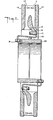
- the disc brake assembly 10 comprising a brake ring 11, a hub 23, and a plurality of pairs of cantilever arms 20, 30 that are connected between the brake ring 11 and the hub 23.
- the brake ring 11 comprises two cast iron braking discs 12, 13 that are spaced apart from each other and connected to each other by a plurality of cooling vanes 14.
- the cooling vanes 14 are circumferentially spaced from each other and provide passages for air to be drawn in and across the inner surfaces of the braking disc 12, 13 to cool them.
- Three such vanes are integral with one another by means of a web 15 that has a lug portion 16 with. an opening for receiving a fastener 17.
- Lug 16 is located between the two outer brake rings and in the path of the cooling air currents generated by vanes 14.
- each cantilever arm has an inner radial portion 26, an elongated axial beam portion 27, and an outer radial portion 28.
- the inner radial portion 26 is provided with one opening 25 for accommodating fastener 17 to fasten the inner radial portion 26 of the arm 20 to the lub 16 of disc 11.
- the outer radial portion 28 of arm 20 has two openings 21, 22 for accommodating other fasteners 29 to thereby fasten the outer radial portion 28 to the hub 23.
- the arms 20 are circumferentially spaced from each other between the hub 23 and the brake ring 11 in a serial manner.
- Each arm 20 extends in the opposite axial direction from each arm on either side of it. In this manner, the arms 20 present a criss-cross appearance and thereby provide the necessary lateral support to counterbalance transverse loads and thus stabilize the brake ring under braking conditions.
- the assembly 10 has its hub 23 pressed onto the axle of a railway car.
- the arms 20, made of high-strength metal alloy, are resilient and expand along with the brake ring.
- the arms 20 experience a minimum amount of stress. Since the arms 20 are staggered on either side of the hub 23, they provide the brake ring 11 with a transverse stability under inertial loading.
- the cantilever arms 20 counterbalance such wobbling and tend to maintain the brake ring 11 in its original plane that is perpendicular to its axis.
- arms 20 there are twelve arms such as arm 20 arranged in six circumferential pairs.
- other numbers of pairs more or less could be adapted to provide a suitable assembly within the spirit and scope of this invention.
- the arms 20, 30 in the preferred embodiment are prestressed radially inwardly toward the hub 23 in order to further minimize the dynamic stresses in the arms 20. Those skilled in the art will appreciate that further stresses could be reduced by lengthening the arm 20 and by reducing its thickness.
- the axial beam portion 27 is axially stressed due to thermal expansion. Such expansion is reduced by locating one connecting lug 16 in the path of the cooling air currents.
- the arm 20 is fashioned as "S" shaped members to elongate the connection between the arm 20 and brake ring 11 an amount equal to the anticipated axial and radial displacements of the arm portion 27.
- an arm 20 has an axial beam portion 27 of 4.5 inches in length and 3/8 inches thick.
- the radial displacement is 0.04 inches when the brake ring thermally expands and the axial displacement is 0.003 inches.
- A of 7 0
- the axial beam portion 27 moves out 0.003 inches and the outer radial portion 28 expands 0.04 inches.
- the disc brake assembly 10 fulfills the objects of this invention by providing a design that will resiliently support a brake ring and also provide transverse stability. Moreover, the assembly 10 is an economical design inasmuch as the most costly metals need only be used for a relatively small number of supporting arms 20. Furthermore, the assembly 10 is easily manufactured since complicated castings of hub members 23 are virtually eliminated. Nevertheless, those skilled . in the art will recognize that the arms 20, 30 could be cast integral with the hub, if so desired.
Landscapes
- Engineering & Computer Science (AREA)
- General Engineering & Computer Science (AREA)
- Mechanical Engineering (AREA)
- Braking Arrangements (AREA)
Applications Claiming Priority (2)
| Application Number | Priority Date | Filing Date | Title |
|---|---|---|---|
| US06/354,994 US4501346A (en) | 1982-03-05 | 1982-03-05 | Disc brake assembly |
| US354994 | 1989-05-22 |
Publications (2)
| Publication Number | Publication Date |
|---|---|
| EP0094480A1 true EP0094480A1 (de) | 1983-11-23 |
| EP0094480B1 EP0094480B1 (de) | 1987-07-22 |
Family
ID=23395818
Family Applications (1)
| Application Number | Title | Priority Date | Filing Date |
|---|---|---|---|
| EP83102159A Expired EP0094480B1 (de) | 1982-03-05 | 1983-03-04 | Zusammengesetzte Scheibenbremse |
Country Status (5)
| Country | Link |
|---|---|
| US (1) | US4501346A (de) |
| EP (1) | EP0094480B1 (de) |
| CA (1) | CA1211386A (de) |
| DE (1) | DE3372651D1 (de) |
| ZA (1) | ZA831119B (de) |
Cited By (4)
| Publication number | Priority date | Publication date | Assignee | Title |
|---|---|---|---|---|
| FR2576991A1 (fr) * | 1985-02-06 | 1986-08-08 | Lucas Ind Plc | Ameliorations relatives a des disques pour des freins a disque |
| FR2576992A1 (fr) * | 1985-02-06 | 1986-08-08 | Lucas Ind Plc | Disque pour frein |
| GB2293866A (en) * | 1994-10-07 | 1996-04-10 | Freni Brembo Spa | Disc for a ventilated disc brake |
| CN108397495A (zh) * | 2017-02-06 | 2018-08-14 | 丰田自动车株式会社 | 制动器模块 |
Families Citing this family (22)
| Publication number | Priority date | Publication date | Assignee | Title |
|---|---|---|---|---|
| CA1219818A (en) * | 1984-03-12 | 1987-03-31 | Roy E. Smith | Brake disc design for wheel mounted discs |
| GB8722349D0 (en) * | 1987-09-23 | 1987-10-28 | Lucas Ind Plc | Disc brakes |
| US5544726A (en) * | 1994-09-06 | 1996-08-13 | Ford Motor Company | Brake rotor with flow through ventilation |
| US6164423A (en) * | 1997-05-02 | 2000-12-26 | Hayes Lemmerz International, Inc. | Vented rotor for caliper disc brakes and the like |
| US6354409B1 (en) * | 2001-01-03 | 2002-03-12 | Delphi Technologies, Inc. | Brake rotor having thermal symmetry |
| DE10148681B4 (de) * | 2001-10-02 | 2008-03-13 | Knorr-Bremse Systeme für Nutzfahrzeuge GmbH | Bremsscheibe für eine Scheibenbremse |
| DE60206058D1 (de) * | 2002-04-23 | 2005-10-13 | Freni Brembo Spa | Scheiben- trägerverbindung für eine scheibenbremse |
| US7568560B2 (en) * | 2004-06-03 | 2009-08-04 | Warren Lin | Center mount two piece brake rotor |
| US7677368B2 (en) * | 2004-06-04 | 2010-03-16 | Brembo S.P.A. | Apparatus for controlling the coning in a brake rotor |
| DE102004045327A1 (de) * | 2004-09-16 | 2006-03-23 | Georg Fischer Fahrzeugtechnik Ag | Bremsscheibenanordung für Fahrzeugräder |
| DE102008042173A1 (de) | 2008-09-17 | 2010-03-18 | Robert Bosch Gmbh | Bremsscheibe |
| DE102008054397B4 (de) * | 2008-12-08 | 2018-08-23 | Sheet Cast Technologies Gmbh | Bremsscheibe sowie Verfahren zur Herstellung einer Bremsscheibe |
| WO2010066753A1 (de) * | 2008-12-08 | 2010-06-17 | Cedas Engineering Gmbh | Bremsscheibe sowie verfahren zur herstellung einer bremsscheibe |
| DE102009027116B4 (de) * | 2009-06-19 | 2014-03-13 | Sheet Cast Technologies Gmbh | Bremsscheibe sowie Verfahren zur Herstellung einer solchen Bremsscheibe |
| DE102009010973A1 (de) * | 2009-02-27 | 2010-09-02 | Bayerische Motoren Werke Aktiengesellschaft | Innenbelüftete Bremsscheibe |
| MX2012006056A (es) * | 2009-11-30 | 2012-07-30 | Wabtec Holding Corp | Disco de freno de vehiculo de ferrocarril. |
| US8851245B2 (en) * | 2010-12-03 | 2014-10-07 | Brake Parts Inc Llc | Brake rotor |
| DE102012110454B3 (de) * | 2012-10-31 | 2014-03-13 | Knorr-Bremse Systeme für Schienenfahrzeuge GmbH | Verbindung einer Wellenbremsscheibe eines Schienenfahrzeugs mit einem fahrzeugseitigen Anschlusselement |
| DE102015110104B4 (de) * | 2015-06-24 | 2025-05-15 | Dr. Ing. H.C. F. Porsche Aktiengesellschaft | Bremsscheibenvorrichtung für ein Fahrzeug |
| IT201700097892A1 (it) * | 2017-08-31 | 2019-03-03 | Freni Brembo Spa | Disco freno per freno a disco |
| US11629765B2 (en) * | 2020-05-15 | 2023-04-18 | Arvinmeritor Technology, Llc | Brake rotor |
| US20230012996A1 (en) * | 2021-07-19 | 2023-01-19 | Poli S.R.L. | Brake system and method |
Citations (11)
| Publication number | Priority date | Publication date | Assignee | Title |
|---|---|---|---|---|
| US2412432A (en) * | 1945-04-26 | 1946-12-10 | American Steel Foundries | Brake rotor |
| US2603316A (en) * | 1952-07-15 | Brake rotor | ||
| US2621762A (en) * | 1946-05-08 | 1952-12-16 | American Steel Foundries | Rotor |
| US2745518A (en) * | 1950-08-15 | 1956-05-15 | American Steel Foundries | Brake rotor |
| DE1200339B (de) * | 1963-05-18 | 1965-09-09 | Knorr Bremse Gmbh | Bremsscheibe fuer Scheibenbremsen, insbesondere fuer Schienenfahrzeuge |
| GB1149126A (en) * | 1966-02-10 | 1969-04-16 | Knorr Bremse Gmbh | Improvements in or relating to discs for disc brakes |
| DE2025625A1 (de) * | 1969-10-10 | 1971-04-22 | Kombinat VEB Lokomotivbau Elektro technische Werke Hans Beimler, χ 1422 Hennigsdorf | Bremsscheibe fur Scheibenbremsen |
| US4002227A (en) * | 1974-10-11 | 1977-01-11 | Pont-A-Mousson S.A. | Brake disc assembly |
| US4077501A (en) * | 1977-01-21 | 1978-03-07 | Westinghouse Air Brake Company | Disc for disc brake unit |
| US4083435A (en) * | 1976-02-11 | 1978-04-11 | Bergische Stahl-Industrie | Brake disc with improved ventilation cooling |
| GB2090636A (en) * | 1980-12-15 | 1982-07-14 | American Standard Inc | Flexible hub for mounting a brake disc on a wheel |
Family Cites Families (7)
| Publication number | Priority date | Publication date | Assignee | Title |
|---|---|---|---|---|
| US2682936A (en) * | 1948-07-15 | 1954-07-06 | Gen Motors Corp | Prestressed brake disk |
| US2765881A (en) * | 1949-12-09 | 1956-10-09 | Raymond C Pierce | Brake rotor |
| US2753959A (en) * | 1951-04-12 | 1956-07-10 | American Steel Foundries | Brake rotor |
| US2769512A (en) * | 1951-11-02 | 1956-11-06 | American Steel Foundries | Brake rotor |
| US3101272A (en) * | 1959-08-04 | 1963-08-20 | Glenn W Setzer | Process for improving structural members and improved structural members |
| US3335482A (en) * | 1962-10-18 | 1967-08-15 | Samuel F Mcclatchie | Assembly of blower wheels |
| US3378114A (en) * | 1966-08-17 | 1968-04-16 | Girling Ltd | Discs for disc brakes |
-
1982
- 1982-03-05 US US06/354,994 patent/US4501346A/en not_active Expired - Lifetime
-
1983
- 1983-02-17 CA CA000421805A patent/CA1211386A/en not_active Expired
- 1983-02-18 ZA ZA831119A patent/ZA831119B/xx unknown
- 1983-03-04 DE DE8383102159T patent/DE3372651D1/de not_active Expired
- 1983-03-04 EP EP83102159A patent/EP0094480B1/de not_active Expired
Patent Citations (11)
| Publication number | Priority date | Publication date | Assignee | Title |
|---|---|---|---|---|
| US2603316A (en) * | 1952-07-15 | Brake rotor | ||
| US2412432A (en) * | 1945-04-26 | 1946-12-10 | American Steel Foundries | Brake rotor |
| US2621762A (en) * | 1946-05-08 | 1952-12-16 | American Steel Foundries | Rotor |
| US2745518A (en) * | 1950-08-15 | 1956-05-15 | American Steel Foundries | Brake rotor |
| DE1200339B (de) * | 1963-05-18 | 1965-09-09 | Knorr Bremse Gmbh | Bremsscheibe fuer Scheibenbremsen, insbesondere fuer Schienenfahrzeuge |
| GB1149126A (en) * | 1966-02-10 | 1969-04-16 | Knorr Bremse Gmbh | Improvements in or relating to discs for disc brakes |
| DE2025625A1 (de) * | 1969-10-10 | 1971-04-22 | Kombinat VEB Lokomotivbau Elektro technische Werke Hans Beimler, χ 1422 Hennigsdorf | Bremsscheibe fur Scheibenbremsen |
| US4002227A (en) * | 1974-10-11 | 1977-01-11 | Pont-A-Mousson S.A. | Brake disc assembly |
| US4083435A (en) * | 1976-02-11 | 1978-04-11 | Bergische Stahl-Industrie | Brake disc with improved ventilation cooling |
| US4077501A (en) * | 1977-01-21 | 1978-03-07 | Westinghouse Air Brake Company | Disc for disc brake unit |
| GB2090636A (en) * | 1980-12-15 | 1982-07-14 | American Standard Inc | Flexible hub for mounting a brake disc on a wheel |
Cited By (7)
| Publication number | Priority date | Publication date | Assignee | Title |
|---|---|---|---|---|
| FR2576991A1 (fr) * | 1985-02-06 | 1986-08-08 | Lucas Ind Plc | Ameliorations relatives a des disques pour des freins a disque |
| FR2576992A1 (fr) * | 1985-02-06 | 1986-08-08 | Lucas Ind Plc | Disque pour frein |
| GB2172676A (en) * | 1985-02-06 | 1986-09-24 | Lucas Ind Plc | Improvements relating to discs for disc brakes |
| GB2293866A (en) * | 1994-10-07 | 1996-04-10 | Freni Brembo Spa | Disc for a ventilated disc brake |
| GB2293866B (en) * | 1994-10-07 | 1998-10-07 | Freni Brembo Spa | A disc for a ventilated disc brake |
| CN108397495A (zh) * | 2017-02-06 | 2018-08-14 | 丰田自动车株式会社 | 制动器模块 |
| EP3361116A1 (de) * | 2017-02-06 | 2018-08-15 | Toyota Jidosha Kabushiki Kaisha | Bremsmodul |
Also Published As
| Publication number | Publication date |
|---|---|
| CA1211386A (en) | 1986-09-16 |
| DE3372651D1 (en) | 1987-08-27 |
| EP0094480B1 (de) | 1987-07-22 |
| US4501346A (en) | 1985-02-26 |
| ZA831119B (en) | 1983-11-30 |
Similar Documents
| Publication | Publication Date | Title |
|---|---|---|
| EP0094480B1 (de) | Zusammengesetzte Scheibenbremse | |
| US4613021A (en) | Brake disc with removable pads | |
| US4281745A (en) | Brake disk for disk brakes on a rail vehicle | |
| US5544726A (en) | Brake rotor with flow through ventilation | |
| US2873088A (en) | Lightweight rotor construction | |
| EP0127932A1 (de) | Bremsscheibenaufbau | |
| US5850895A (en) | Metallic aircraft brake disk having thermal relief slots | |
| EP1423625B1 (de) | Mehrscheibenbremsenstrukturasymmetrie | |
| JPS60234140A (ja) | 摩擦デイスク | |
| US4856619A (en) | Aircraft wheel drive key and heatshield assembly | |
| SE461261B (sv) | Primaerupphaengningsanordning foer en raelsgaaende vagn | |
| US6988598B2 (en) | Disc brake rotor mounting system | |
| EP0198217A1 (de) | Scheibenbremsmotor | |
| CA1219818A (en) | Brake disc design for wheel mounted discs | |
| EP0453075A1 (de) | Räder mit eingebauten Bremsscheiben | |
| US20080060890A1 (en) | Flexibly mounted disc brake rotor for pneumatic, electromotive, and/or hydraulic disc brakes | |
| US6135248A (en) | Brake disk | |
| US5188203A (en) | Weight reduced brake rotor | |
| US3507370A (en) | Brake disk for railway vehicle wheels | |
| EP2128477A1 (de) | Scheibenrotor für Scheibenbremse | |
| US6397982B2 (en) | Disc brake housing | |
| EP4010202B1 (de) | Radnabe mit integriertem kreisförmigem bremselement | |
| GB2172676A (en) | Improvements relating to discs for disc brakes | |
| US12460689B2 (en) | Brake assembly including expandable rotor | |
| EP0216534B1 (de) | Am Rad angeordnete Scheiben |
Legal Events
| Date | Code | Title | Description |
|---|---|---|---|
| PUAI | Public reference made under article 153(3) epc to a published international application that has entered the european phase |
Free format text: ORIGINAL CODE: 0009012 |
|
| AK | Designated contracting states |
Designated state(s): DE FR GB IT |
|
| 17P | Request for examination filed |
Effective date: 19840507 |
|
| GRAA | (expected) grant |
Free format text: ORIGINAL CODE: 0009210 |
|
| AK | Designated contracting states |
Kind code of ref document: B1 Designated state(s): DE FR GB IT |
|
| PG25 | Lapsed in a contracting state [announced via postgrant information from national office to epo] |
Ref country code: IT Free format text: LAPSE BECAUSE OF FAILURE TO SUBMIT A TRANSLATION OF THE DESCRIPTION OR TO PAY THE FEE WITHIN THE PRESCRIBED TIME-LIMIT;WARNING: LAPSES OF ITALIAN PATENTS WITH EFFECTIVE DATE BEFORE 2007 MAY HAVE OCCURRED AT ANY TIME BEFORE 2007. THE CORRECT EFFECTIVE DATE MAY BE DIFFERENT FROM THE ONE RECORDED. Effective date: 19870722 |
|
| REF | Corresponds to: |
Ref document number: 3372651 Country of ref document: DE Date of ref document: 19870827 |
|
| ET | Fr: translation filed | ||
| PLBE | No opposition filed within time limit |
Free format text: ORIGINAL CODE: 0009261 |
|
| STAA | Information on the status of an ep patent application or granted ep patent |
Free format text: STATUS: NO OPPOSITION FILED WITHIN TIME LIMIT |
|
| 26N | No opposition filed | ||
| PG25 | Lapsed in a contracting state [announced via postgrant information from national office to epo] |
Ref country code: GB Free format text: LAPSE BECAUSE OF NON-PAYMENT OF DUE FEES Effective date: 19881122 |
|
| GBPC | Gb: european patent ceased through non-payment of renewal fee | ||
| PG25 | Lapsed in a contracting state [announced via postgrant information from national office to epo] |
Ref country code: FR Free format text: LAPSE BECAUSE OF NON-PAYMENT OF DUE FEES Effective date: 19881130 |
|
| PG25 | Lapsed in a contracting state [announced via postgrant information from national office to epo] |
Ref country code: DE Effective date: 19881201 |
|
| REG | Reference to a national code |
Ref country code: FR Ref legal event code: ST |