EP0094654A2 - Châssis pour véhicule chenillé - Google Patents
Châssis pour véhicule chenillé Download PDFInfo
- Publication number
- EP0094654A2 EP0094654A2 EP83104773A EP83104773A EP0094654A2 EP 0094654 A2 EP0094654 A2 EP 0094654A2 EP 83104773 A EP83104773 A EP 83104773A EP 83104773 A EP83104773 A EP 83104773A EP 0094654 A2 EP0094654 A2 EP 0094654A2
- Authority
- EP
- European Patent Office
- Prior art keywords
- spacer
- parts
- strut
- vehicle frame
- main frame
- Prior art date
- Legal status (The legal status is an assumption and is not a legal conclusion. Google has not performed a legal analysis and makes no representation as to the accuracy of the status listed.)
- Granted
Links
Images

Classifications
-
- B—PERFORMING OPERATIONS; TRANSPORTING
- B62—LAND VEHICLES FOR TRAVELLING OTHERWISE THAN ON RAILS
- B62D—MOTOR VEHICLES; TRAILERS
- B62D55/00—Endless track vehicles
- B62D55/08—Endless track units; Parts thereof
- B62D55/084—Endless-track units or carriages mounted separably, adjustably or extensibly on vehicles, e.g. portable track units
Definitions
- the invention relates to a caterpillar vehicle frame with two spaced-apart main frames extending in the direction of travel, with a horizontal axis arranged between them and fixed to them in the rear area, with two diagonally extending struts extending inwards and backwards and with a fastening for Fixing the strut on the associated main frame so that the rear end of the strut is articulated on the axis.
- German Patent 25 18 711 Endless vehicle chains are guided over the main frames, while the rear ends of these main frames are taken up by a chassis of a motor vehicle via said axis.
- the struts mentioned serve to compensate for the tensile or compressive forces exerted laterally on the main frame, which occur particularly when the vehicle is turned.
- the invention has for its object to improve the caterpillar vehicle frame explained above so that the usual diagonal struts can continue to be used when converting to widened chains.
- said attachment has a spacer which is attached with one side to the associated main frame, while the associated strut is attached to another side of the spacer.
- the spacer is constructed in three parts, the first part of the spacer having a horizontal upper side for fastening the associated strut, vertically spaced from it two mounting surfaces horizontally extending in opposite directions for fastening the spacer to the associated main frame, and Has top and mounting surfaces interconnecting end walls, on which laterally substantially vertical, the second and third part forming side parts are attached, on the upper edge of which the top of the first part rests and is fastened with a horizontal section.
- stiffeners can be attached between the two side parts.
- the three parts forming the spacer can be welded together.
- the strut is also attached to the upper side of the first part of the spacer and the two mounting surfaces of the first part mentioned are attached to the associated main frame, preferably by welding.
- the parts forming the spacer can be produced from sheet metal in a very simple manner.
- the first part of the spacer consist of a sheet metal strip which is bent in the form of a flat bowl in a side view, the bottom of which forms the upper side for fastening the strut and the edge of the bowl forms the said mounting surfaces.
- the sheet metal strip bent in this way is covered on both sides by the side parts mentioned, which on the one hand abut the lateral edge of the first part and on the other hand are overlapped by the latter.
- the parts can be mutually adjusted very easily, with relatively high manufacturing tolerances being possible.
- FIG. 1 shows a crawler frame, with 10 in having a right crawler vehicle frame 12 and a left crawler vehicle frame 14 both 16 and 18 serve auptrahmeners for receiving a respective H, are shown on the not shown in the drawing endless vehicle tracks.
- the rear ends of the main frame parts 16, 18 are received by a chassis of a motor vehicle, not shown in the drawing, via a transverse axis 20 which is supported with its two ends in the main frame parts 16, 18.
- the crawler vehicle frames 12, 14 have corresponding diagonal struts 22, 24, which on the one hand each have a spacer 21, 23 with the associated main frame 16 and 18 are connected and are hinged at their other end to the axis 20.
- the right diagonal strut 22 has a front arm 26 which is welded to the top of the spacer 21, which in turn is centrally welded to the inner surface of the main frame 16.
- the aforementioned arm 26 extends from the spacer 21 inwards and backwards and ends at its rear end 28 directly in front of the axis 20 and is articulated on it as in the German patent specification 25 18 711 is explained in detail.
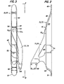
- FIGS. 2 and 3 show that each spacer 21, 23 is constructed in three parts and consists of a first part 41, which has a substantially flat horizontal upper side 43, the front and rear end walls 45 extending outwards and in opposite directions , 46 merges, which in turn merge into flat mounting surfaces 49, 51 running parallel to the upper side 43.
- This first part 41 is covered on its two long sides by a side part 53, 54, which are welded with their flat side against the side edge of the end walls 45, 46 and with their bottom edge against the main frame 16 and 18, respectively.
- the upper side 43 of the first part 41 overlaps the upper edge of the two side parts 53, 54 with longitudinal edges 43a and is welded to the latter in this area.
- Stiffeners 46 can be provided between the two side parts 53, 54, which are indicated by dashed lines in FIGS. 2 and 3.
- the illustrated embodiment shows that the three parts 41, 53 and 54 forming the spacers 21 and 23 abut each other and partially overlap each other, so that there is a self-adjustment between the three parts, which allows large manufacturing tolerances.
- the three parts are very easy to manufacture from sheet metal and can be connected to one another without great machining effort. This makes it possible to provide a correspondingly adapted spacer 21, 23 in a simple manner while maintaining the usual diagonal struts 22, 24 when converting to wider chains.
Landscapes
- Engineering & Computer Science (AREA)
- Chemical & Material Sciences (AREA)
- Combustion & Propulsion (AREA)
- Transportation (AREA)
- Mechanical Engineering (AREA)
- Body Structure For Vehicles (AREA)
- Jib Cranes (AREA)
Applications Claiming Priority (2)
| Application Number | Priority Date | Filing Date | Title |
|---|---|---|---|
| US06/378,699 US4577717A (en) | 1982-05-17 | 1982-05-17 | Track unit extension for wide track crawler vehicles |
| US378699 | 1982-05-17 |
Publications (3)
| Publication Number | Publication Date |
|---|---|
| EP0094654A2 true EP0094654A2 (fr) | 1983-11-23 |
| EP0094654A3 EP0094654A3 (en) | 1986-07-09 |
| EP0094654B1 EP0094654B1 (fr) | 1987-09-23 |
Family
ID=23494196
Family Applications (1)
| Application Number | Title | Priority Date | Filing Date |
|---|---|---|---|
| EP83104773A Expired EP0094654B1 (fr) | 1982-05-17 | 1983-05-14 | Châssis pour véhicule chenillé |
Country Status (6)
| Country | Link |
|---|---|
| US (1) | US4577717A (fr) |
| EP (1) | EP0094654B1 (fr) |
| JP (1) | JPS58209665A (fr) |
| CA (1) | CA1201145A (fr) |
| DE (1) | DE3373800D1 (fr) |
| FI (1) | FI831676L (fr) |
Families Citing this family (2)
| Publication number | Priority date | Publication date | Assignee | Title |
|---|---|---|---|---|
| US5254774A (en) * | 1992-12-28 | 1993-10-19 | Minnesota Mining And Manufacturing Company | Preparation of hexafluoropropene oligomers |
| JP2005271602A (ja) * | 2004-03-22 | 2005-10-06 | Komatsu Ltd | 建設機械 |
Family Cites Families (9)
| Publication number | Priority date | Publication date | Assignee | Title |
|---|---|---|---|---|
| US1944393A (en) * | 1932-05-14 | 1934-01-23 | Int Harvester Co | Tracklaying tractor |
| US2035858A (en) * | 1934-10-18 | 1936-03-31 | Bucyrus Eric Company | Creeping traction |
| DE726497C (de) * | 1938-06-10 | 1943-07-28 | Heinrich Lanz Ag | Rollenrahmen fuer Raupenschlepper |
| US3037571A (en) * | 1959-08-17 | 1962-06-05 | Schield Bantam Company | Wide base crawler |
| US3674105A (en) * | 1970-10-30 | 1972-07-04 | Deere & Co | Drive axle for wide-track crawler vehicles |
| US3820616A (en) * | 1972-02-03 | 1974-06-28 | American Hoist & Derrick Co | Crawler vehicle with dual extensible side frames |
| US3825088A (en) * | 1972-12-07 | 1974-07-23 | Caterpillar Tractor Co | Equalizer bar mounting for track-type vehicles |
| US3894597A (en) * | 1974-05-01 | 1975-07-15 | Deere & Co | Diagonal brace for tractor frame of track-laying tractor |
| US3924703A (en) * | 1974-11-08 | 1975-12-09 | Caterpillar Tractor Co | Equalizer bar assembly for crawler-type vehicles |
-
1982
- 1982-05-17 US US06/378,699 patent/US4577717A/en not_active Expired - Fee Related
-
1983
- 1983-05-11 CA CA000427901A patent/CA1201145A/fr not_active Expired
- 1983-05-13 FI FI831676A patent/FI831676L/fi not_active Application Discontinuation
- 1983-05-14 DE DE8383104773T patent/DE3373800D1/de not_active Expired
- 1983-05-14 EP EP83104773A patent/EP0094654B1/fr not_active Expired
- 1983-05-17 JP JP58086508A patent/JPS58209665A/ja active Pending
Also Published As
| Publication number | Publication date |
|---|---|
| FI831676A7 (fi) | 1983-11-18 |
| US4577717A (en) | 1986-03-25 |
| FI831676A0 (fi) | 1983-05-13 |
| EP0094654A3 (en) | 1986-07-09 |
| EP0094654B1 (fr) | 1987-09-23 |
| FI831676L (fi) | 1983-11-18 |
| JPS58209665A (ja) | 1983-12-06 |
| CA1201145A (fr) | 1986-02-25 |
| DE3373800D1 (en) | 1987-10-29 |
Similar Documents
| Publication | Publication Date | Title |
|---|---|---|
| DE19515979C2 (de) | Hintere Aufbaustruktur eines Fahrzeugs | |
| DE19638156B4 (de) | Aufbau für oberen Karosserieabschnitt einer Fahrzeugkarosserie | |
| DE68909570T2 (de) | Kabinenstruktur für ein schweres Motorfahrzeug. | |
| DE4008896C2 (de) | Motorraumaufbau eines Kraftfahrzeuges | |
| DE69423972T2 (de) | Endabschnitt eines rahmenteils für ein fahrzeug | |
| DE10300393B3 (de) | Rahmenvorderteil für ein Nutzfahrzeug | |
| DE10316205A1 (de) | Fahrzeugkarosseriestruktur | |
| DE102009013893A1 (de) | A-Säulenverbindung für ein Kraftfahrzeug | |
| DE112015000063B4 (de) | Fahrzeugkarosserie mit Öffnung in einem Fahrzeugkarosserie-Heckabschnitt | |
| DE2636365C2 (de) | Unterbau für eine Kraftfahrzeugkarosserie | |
| DE2604882C2 (de) | Befahrbare Fläche für mechanische Parkeinrichtungen, Rampen, Hebebühnen o.dgl. | |
| DE3337708A1 (de) | Kraftfahrzeugkarosserie | |
| DE3813049A1 (de) | Gleitschuh, insbesondere fuer fahrzeugschiebedaecher | |
| DE19812679B4 (de) | Versteifungsanordnung für eine Unterbaugruppe eines Kraftfahrzeugs | |
| DE2325692A1 (de) | Fahrzeugrahmen | |
| DE634467C (de) | Fahrgestellrahmen, insbesondere fuer Kraftfahrzeuge | |
| DE2420889A1 (de) | Kraftfahrzeughinterachse mit laengslenkern und einer die laengslenker verbindenden, biegesteifen und drillweichen querstrebe | |
| EP0094654B1 (fr) | Châssis pour véhicule chenillé | |
| DE3122531A1 (de) | Bodengruppe eines kraftfahrzeugs | |
| DE2837061A1 (de) | Aussenhautschweissverbindung | |
| EP0087504A1 (fr) | Remorque pour véhicules à moteur | |
| DE2628537C3 (de) | Tragelement | |
| DE19724557B4 (de) | Selbsttragende Fahrzeugkarosserie | |
| DE967939C (de) | Bodenblechrahmen als Bestandteil selbsttragender Fahrzeugwagenkaesten | |
| DE2522838A1 (de) | Kettenfahrzeug |
Legal Events
| Date | Code | Title | Description |
|---|---|---|---|
| PUAI | Public reference made under article 153(3) epc to a published international application that has entered the european phase |
Free format text: ORIGINAL CODE: 0009012 |
|
| AK | Designated contracting states |
Designated state(s): DE FR GB IT SE |
|
| ITCL | It: translation for ep claims filed |
Representative=s name: LENZI & C. |
|
| EL | Fr: translation of claims filed | ||
| PUAL | Search report despatched |
Free format text: ORIGINAL CODE: 0009013 |
|
| AK | Designated contracting states |
Kind code of ref document: A3 Designated state(s): DE FR GB IT SE |
|
| 17P | Request for examination filed |
Effective date: 19860704 |
|
| 17Q | First examination report despatched |
Effective date: 19861205 |
|
| ITF | It: translation for a ep patent filed | ||
| GRAA | (expected) grant |
Free format text: ORIGINAL CODE: 0009210 |
|
| AK | Designated contracting states |
Kind code of ref document: B1 Designated state(s): DE FR GB IT SE |
|
| PG25 | Lapsed in a contracting state [announced via postgrant information from national office to epo] |
Ref country code: SE Effective date: 19870930 |
|
| REF | Corresponds to: |
Ref document number: 3373800 Country of ref document: DE Date of ref document: 19871029 |
|
| ET | Fr: translation filed | ||
| GBT | Gb: translation of ep patent filed (gb section 77(6)(a)/1977) | ||
| PLBE | No opposition filed within time limit |
Free format text: ORIGINAL CODE: 0009261 |
|
| STAA | Information on the status of an ep patent application or granted ep patent |
Free format text: STATUS: NO OPPOSITION FILED WITHIN TIME LIMIT |
|
| 26N | No opposition filed | ||
| PGFP | Annual fee paid to national office [announced via postgrant information from national office to epo] |
Ref country code: GB Payment date: 19890430 Year of fee payment: 7 |
|
| PGFP | Annual fee paid to national office [announced via postgrant information from national office to epo] |
Ref country code: FR Payment date: 19890505 Year of fee payment: 7 |
|
| ITTA | It: last paid annual fee | ||
| PGFP | Annual fee paid to national office [announced via postgrant information from national office to epo] |
Ref country code: DE Payment date: 19890724 Year of fee payment: 7 |
|
| PG25 | Lapsed in a contracting state [announced via postgrant information from national office to epo] |
Ref country code: GB Effective date: 19900514 |
|
| GBPC | Gb: european patent ceased through non-payment of renewal fee | ||
| PG25 | Lapsed in a contracting state [announced via postgrant information from national office to epo] |
Ref country code: FR Effective date: 19910131 |
|
| PG25 | Lapsed in a contracting state [announced via postgrant information from national office to epo] |
Ref country code: DE Effective date: 19910201 |
|
| REG | Reference to a national code |
Ref country code: FR Ref legal event code: ST |