EP0094664B1 - Ölpneumatisches Energierückgewinnungssystem für Stadtfahrzeuge - Google Patents
Ölpneumatisches Energierückgewinnungssystem für Stadtfahrzeuge Download PDFInfo
- Publication number
- EP0094664B1 EP0094664B1 EP83104803A EP83104803A EP0094664B1 EP 0094664 B1 EP0094664 B1 EP 0094664B1 EP 83104803 A EP83104803 A EP 83104803A EP 83104803 A EP83104803 A EP 83104803A EP 0094664 B1 EP0094664 B1 EP 0094664B1
- Authority
- EP
- European Patent Office
- Prior art keywords
- heat engine
- transmission
- vehicle
- train
- connection
- Prior art date
- Legal status (The legal status is an assumption and is not a legal conclusion. Google has not performed a legal analysis and makes no representation as to the accuracy of the status listed.)
- Expired
Links
Images


Classifications
-
- F—MECHANICAL ENGINEERING; LIGHTING; HEATING; WEAPONS; BLASTING
- F16—ENGINEERING ELEMENTS AND UNITS; GENERAL MEASURES FOR PRODUCING AND MAINTAINING EFFECTIVE FUNCTIONING OF MACHINES OR INSTALLATIONS; THERMAL INSULATION IN GENERAL
- F16H—GEARING
- F16H47/00—Combinations of mechanical gearing with fluid clutches or fluid gearing
- F16H47/02—Combinations of mechanical gearing with fluid clutches or fluid gearing the fluid gearing being of the volumetric type
- F16H47/04—Combinations of mechanical gearing with fluid clutches or fluid gearing the fluid gearing being of the volumetric type the mechanical gearing being of the type with members having orbital motion
-
- B—PERFORMING OPERATIONS; TRANSPORTING
- B60—VEHICLES IN GENERAL
- B60K—ARRANGEMENT OR MOUNTING OF PROPULSION UNITS OR OF TRANSMISSIONS IN VEHICLES; ARRANGEMENT OR MOUNTING OF PLURAL DIVERSE PRIME-MOVERS IN VEHICLES; AUXILIARY DRIVES FOR VEHICLES; INSTRUMENTATION OR DASHBOARDS FOR VEHICLES; ARRANGEMENTS IN CONNECTION WITH COOLING, AIR INTAKE, GAS EXHAUST OR FUEL SUPPLY OF PROPULSION UNITS IN VEHICLES
- B60K6/00—Arrangement or mounting of plural diverse prime-movers for mutual or common propulsion, e.g. hybrid propulsion systems comprising electric motors and internal combustion engines
- B60K6/08—Prime-movers comprising combustion engines and mechanical or fluid energy storing means
- B60K6/12—Prime-movers comprising combustion engines and mechanical or fluid energy storing means by means of a chargeable fluidic accumulator
-
- B—PERFORMING OPERATIONS; TRANSPORTING
- B60—VEHICLES IN GENERAL
- B60T—VEHICLE BRAKE CONTROL SYSTEMS OR PARTS THEREOF; BRAKE CONTROL SYSTEMS OR PARTS THEREOF, IN GENERAL; ARRANGEMENT OF BRAKING ELEMENTS ON VEHICLES IN GENERAL; PORTABLE DEVICES FOR PREVENTING UNWANTED MOVEMENT OF VEHICLES; VEHICLE MODIFICATIONS TO FACILITATE COOLING OF BRAKES
- B60T1/00—Arrangements of braking elements, i.e. of those parts where braking effect occurs specially for vehicles
- B60T1/02—Arrangements of braking elements, i.e. of those parts where braking effect occurs specially for vehicles acting by retarding wheels
- B60T1/10—Arrangements of braking elements, i.e. of those parts where braking effect occurs specially for vehicles acting by retarding wheels by utilising wheel movement for accumulating energy, e.g. driving air compressors
-
- F—MECHANICAL ENGINEERING; LIGHTING; HEATING; WEAPONS; BLASTING
- F16—ENGINEERING ELEMENTS AND UNITS; GENERAL MEASURES FOR PRODUCING AND MAINTAINING EFFECTIVE FUNCTIONING OF MACHINES OR INSTALLATIONS; THERMAL INSULATION IN GENERAL
- F16H—GEARING
- F16H61/00—Control functions within control units of change-speed- or reversing-gearings for conveying rotary motion ; Control of exclusively fluid gearing, friction gearing, gearings with endless flexible members or other particular types of gearing
- F16H61/38—Control of exclusively fluid gearing
- F16H61/40—Control of exclusively fluid gearing hydrostatic
- F16H61/4078—Fluid exchange between hydrostatic circuits and external sources or consumers
- F16H61/4096—Fluid exchange between hydrostatic circuits and external sources or consumers with pressure accumulators
-
- B—PERFORMING OPERATIONS; TRANSPORTING
- B60—VEHICLES IN GENERAL
- B60W—CONJOINT CONTROL OF VEHICLE SUB-UNITS OF DIFFERENT TYPE OR DIFFERENT FUNCTION; CONTROL SYSTEMS SPECIALLY ADAPTED FOR HYBRID VEHICLES; ROAD VEHICLE DRIVE CONTROL SYSTEMS FOR PURPOSES NOT RELATED TO THE CONTROL OF A PARTICULAR SUB-UNIT
- B60W30/00—Purposes of road vehicle drive control systems not related to the control of a particular sub-unit, e.g. of systems using conjoint control of vehicle sub-units
- B60W30/18—Propelling the vehicle
- B60W30/18009—Propelling the vehicle related to particular drive situations
- B60W30/18109—Braking
- B60W30/18127—Regenerative braking
-
- F—MECHANICAL ENGINEERING; LIGHTING; HEATING; WEAPONS; BLASTING
- F16—ENGINEERING ELEMENTS AND UNITS; GENERAL MEASURES FOR PRODUCING AND MAINTAINING EFFECTIVE FUNCTIONING OF MACHINES OR INSTALLATIONS; THERMAL INSULATION IN GENERAL
- F16H—GEARING
- F16H37/00—Combinations of mechanical gearings, not provided for in groups F16H1/00 - F16H35/00
- F16H37/02—Combinations of mechanical gearings, not provided for in groups F16H1/00 - F16H35/00 comprising essentially only toothed or friction gearings
- F16H37/06—Combinations of mechanical gearings, not provided for in groups F16H1/00 - F16H35/00 comprising essentially only toothed or friction gearings with a plurality of driving or driven shafts; with arrangements for dividing torque between two or more intermediate shafts
- F16H37/08—Combinations of mechanical gearings, not provided for in groups F16H1/00 - F16H35/00 comprising essentially only toothed or friction gearings with a plurality of driving or driven shafts; with arrangements for dividing torque between two or more intermediate shafts with differential gearing
- F16H37/10—Combinations of mechanical gearings, not provided for in groups F16H1/00 - F16H35/00 comprising essentially only toothed or friction gearings with a plurality of driving or driven shafts; with arrangements for dividing torque between two or more intermediate shafts with differential gearing at both ends of intermediate shafts
- F16H2037/102—Combinations of mechanical gearings, not provided for in groups F16H1/00 - F16H35/00 comprising essentially only toothed or friction gearings with a plurality of driving or driven shafts; with arrangements for dividing torque between two or more intermediate shafts with differential gearing at both ends of intermediate shafts the input or output shaft of the transmission is connected or connectable to two or more differentials
-
- F—MECHANICAL ENGINEERING; LIGHTING; HEATING; WEAPONS; BLASTING
- F16—ENGINEERING ELEMENTS AND UNITS; GENERAL MEASURES FOR PRODUCING AND MAINTAINING EFFECTIVE FUNCTIONING OF MACHINES OR INSTALLATIONS; THERMAL INSULATION IN GENERAL
- F16H—GEARING
- F16H47/00—Combinations of mechanical gearing with fluid clutches or fluid gearing
- F16H47/02—Combinations of mechanical gearing with fluid clutches or fluid gearing the fluid gearing being of the volumetric type
- F16H47/04—Combinations of mechanical gearing with fluid clutches or fluid gearing the fluid gearing being of the volumetric type the mechanical gearing being of the type with members having orbital motion
- F16H2047/045—Combinations of mechanical gearing with fluid clutches or fluid gearing the fluid gearing being of the volumetric type the mechanical gearing being of the type with members having orbital motion the fluid gearing comprising a plurality of pumps or motors
-
- Y—GENERAL TAGGING OF NEW TECHNOLOGICAL DEVELOPMENTS; GENERAL TAGGING OF CROSS-SECTIONAL TECHNOLOGIES SPANNING OVER SEVERAL SECTIONS OF THE IPC; TECHNICAL SUBJECTS COVERED BY FORMER USPC CROSS-REFERENCE ART COLLECTIONS [XRACs] AND DIGESTS
- Y02—TECHNOLOGIES OR APPLICATIONS FOR MITIGATION OR ADAPTATION AGAINST CLIMATE CHANGE
- Y02T—CLIMATE CHANGE MITIGATION TECHNOLOGIES RELATED TO TRANSPORTATION
- Y02T10/00—Road transport of goods or passengers
- Y02T10/60—Other road transportation technologies with climate change mitigation effect
- Y02T10/62—Hybrid vehicles
Definitions
- the invention relates to the recovery of braking energy on a vehicle, in particular on an urban vehicle such as a bus subjected to frequent braking and starting.
- Some public transport vehicles use a flywheel, an electric accumulator or an oleopneumatic accumulator for this.
- a hydrostatic element having the function of a pump or motor is generally used to fill and empty the accumulator. This element is added to the classic automatic transmission, generally on the power take-off.
- hydrostatic power derivation transmissions there is one particularly interesting, corresponding to the preamble of claim 1 and described in French patent 80 10 953 (2,482,692) in the name of the applicant for a "continuously variable transmission with two modes of operation ".
- Such a transmission is based essentially on the use of a double differential, or mechanism with four shafts, two of which are coupled to hydrostatic machines, with a staggering of the ratios such that the transmission can ensure a starting phase on torque converter hydrokinetic, followed by a mode of operation having a high efficiency by the fact that the derived power passing through the hydrostatic machines represents a small fraction of the motive power.
- the object of the invention is to use all the elements constituting such a transmission to further ensure the storage and destocking of the braking energy in an oleopneumatic accumulator, without this leading to increased complexity of the mechanics. of the transmission itself, differentials and hydrostatic machines.
- the invention provides a solution characterized as in the second part of claim 1.
- the invention consists in combining, with the mechanical and hydraulic members of a transmission of the aforementioned type and at least one oleopneumatic accumulation tank, an electronic logic actuating electro-hydraulic switching members so as to connect the various members, in particular hydraulic pumps and motors and the accumulator tank, in order to obtain the various desired phases of braking, with or without recovery, and of hybrid traction on the oleopneumatic accumulator and the heat engine.
- the invention provides as electrohydraulic switching members additional essentially two electrohydraulic reversing switches, with parallel and crossed couplings, arranged the first in the return circuit joining the hydrostatic pump to the hydrostatic motor, and the second in the return circuit joining the pump to the oleopneumatic accumulator and there reserve at low pressure.
- the invention like the aforementioned patent, is based on the use of a differential mechanism with four shafts 1, 2, 3, and 4.
- the mechanism used is different from those already described in the aforementioned patent, but it is also a known mechanism and it goes without saying that the invention would also apply to any other type of mechanism with four shafts.
- the heat engine 5 is connected to the transmission by means of a conventional torque converter 6 provided with a clutch. bridging age not shown.
- the turbine shaft coming out of the torque converter is connected to an inverter 7 making it possible to switch forward, reverse and which is constituted for example by a planetary train with two groups of satellites, the forward being obtained by joining complete of the assembly by a controlled multi-plate clutch 8 while the reverse gear is obtained by blocking the crown on the casing by a controlled brake 9.
- this reversing mechanism could alternatively be arranged on the 'output shaft 2.
- this inverter has not been shown in the diagrams of fig. 2 and 4.
- the four-shaft mechanism used in the example chosen and designated as a whole by 10 is of the Simpson train type with common solar.
- the two trains are respectively designated as a whole by 11 and 12 in FIG. 1.
- the input shaft 1 is connected to the planet carrier of the train 11, while the output shaft 2 connects both the crown of the train 11 and the planet carrier of the train 12.
- the tree 3 constitutes the solar common to two trains 11 and 12 and is connected to a hydrostatic machine 3a via a chain transmission 13.
- the shaft 4, integral with the crown of the train 12, is connected by another chain 14 to a set of two hydrostatic machines 4a mounted in opposition.
- this shaft 4 is provided with a free wheel 15 acting on the casing so as to prohibit the reverse rotation of this shaft and thus relieve the hydraulic machines 4a in the start-up phase.
- this four-shaft mechanism is represented schematically as equivalent to two conventional differentials with three shafts D, and D 2 , but this only for the purpose of diagramming because these differentials D 1 and D 2 are not equivalent separately and respectively on trains 11 and 12, but only as a whole.
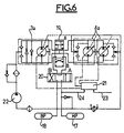
- the present invention shown schematically in FIG. 4, consists in combining the whole of the mechanism and the organs previously described with on the one hand an oleopneumatic accumulator 17 at high pressure, associated with a reservoir 18 at low pressure, and on the other hand a set of two electrohydraulic switches 19 and 20 shown in FIG. 4 and controlled, together with all the other electrohydraulic switches, by an electronic computer 21 shown only in FIG. 6.
- the switch 19 shown schematically in FIG. 4 by a hydraulic distributor, is interposed in the return circuit connecting the machines 3a and 4a so as to allow direct connection or crossing of these connections.
- the switch 20 also shown as a hydraulic distributor, is interposed in the double return pipe circuit connecting the machine 3a to the high pressure accumulator 17 and to the low pressure reserve 18.
- the booster pump 22 which is already used in the prior art to maintain the low pressure circuit under pressure despite the leaks.
- this pump must ensure the low pressure of all the flow absorbed by the hydraulic elements, which may justify a different dimensioning.
- This pump is preferably constituted by a centrifugal pump providing a low pressure of 10 bars, but a volumetric pump with variable displacement could also be used.
- the assembly of the low pressure reservoir 18 placed in the atmosphere and of the booster pump 22 plays the same role as the conventional low pressure accumulator that is found in hybrid assemblies.
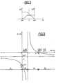
- This curve cuts the vertical axis at a point P, on the ordinate -p3 and the horizontal axis at a point P 2 on the abscissa and it has a horizontal asymptote of ordinate -p4 and a vertical asymptote of abscissa
- the point P2 is a particular point where the torque C1 is zero whatever C2, which means that the motor input is then disconnected from the rest of the mechanism and that this motor operates "fl otta nt".
- the objective of the invention is to use the hydraulic machines 3a and 4a to store and restore the braking energy present on the output shaft (C2w2). We will therefore examine successively the storage and the restitution of this energy.
- This is obtained by adjusting the cubic capacity ratio Cy3 and Cy4 in particular since at all times we have k3 and k4 being fixed transmission ratios between the hydraulic machines 3a and 4a and the corresponding shafts of the four-shaft mechanism, transmission constituted in the example by chains 13 and 14.
- the hydraulic circuit then has its switch 19 in a position A such that the three machines 3a and 4a play the same role, and its switch 20 in a position A corresponding to braking. These two positions A corresponding on the diagrams to the parallel connections.
- the three hydraulic machines 3a and 4a then play the role of pump and deliver into the oleopneumatic accumulator 17 at high pressure (up to 400 bars for example).
- the absolute value of the displacement Cy4 is determined by the computer 21 as a function of the indication received by 23 of the deceleration torque to be produced and the indication received by 24 of the pressure prevailing at all times in the accumulator 17.
- This retarding torque obtained by the hydraulics is also combined with the general braking action and is deduced from the torque of the conventional brakes acting on the axle in question, as is done in a known manner in so-called braking. conjugates. This ensures safety braking at all times regardless of the filling level of the accumulator and does not alter the balance of grip required for handling.
- the heat engine 5 is regulated in speed to maintain at all times, therefore for each speed of the vehicle, a speed to the heat engine in a manner that the hydraulic elements 3a and 4a as well as the mechanism 10 do not pick up abnormal speeds and the deceleration effect is sufficient.
- This setting can for example correspond to the maximum speed of the heat engine.
- the computer 21 tests the filling pressure level of accumulator 17. If the pressure is less than a set value, the computer controls switches 19 and 20 for pure transmission, that is to say with switching 19 in position B and switch 20 on rest in the traction phase.
- the computer determines its use by placing the switch 19 in position A with zero displacement.
- the start on the torque converter 6 is carried out as in pure traction, that is to say by blocking on the freewheel 15. If the driver wishes to brake in this phase, the computer 21 reposition the switch 20 in the position above.
- the computer determines the bridging in a conventional manner by controlling the bridging clutch for a determined slip rate of the speed of the shaft 1 relative to the speed of l 'engine shaft. In the present case, this action simultaneously triggers the restitution action by placing the switch 20 in position B.
- the torque desired by the driver and transmitted by 23 is translated by the computer 21 as a function of the pressure prevailing in the accumulator and arriving by 24 in a control of the displacement ratio. Two cases are then to be considered:
- the computer 21 acts to neutralize the engine 5 and make it floating as explained above, the only parameter to be regular being its speed as a function of that of the vehicle. This action is carried out as described above by actuating the injection pump or by slightly shifting the operating point beyond point P2. The computer then adjusts the absolute value of the displacement Cy4 and Cy2 to obtain the desired torque at all times.
- the switch 20 When the driver modulates his acceleration during a speed stop or goes into braking, the switch 20 is actuated in a direction which acts by isolating the accumulator then by reversing the circuits.
- the same procedure can be carried out on a request for maximum power caused for example by the driver.
- the hybridization according to the invention makes it possible with the minimum of additional members, essentially the switches 19 and 20 as well as the computer 21, in addition to naturally the oleopneumatic accumulator 17, to ensure optimal energy recovery, in the naturally limits the capacity of the accumulator, with in addition an automatic and practically continuous passage through all the necessary phases of traction on converter, then without converter with or without restitution, and braking with or without recovery, and this by simple action on the switches as well as on the displacement controls.
Landscapes
- Engineering & Computer Science (AREA)
- General Engineering & Computer Science (AREA)
- Mechanical Engineering (AREA)
- Chemical & Material Sciences (AREA)
- Combustion & Propulsion (AREA)
- Transportation (AREA)
- Control Of Fluid Gearings (AREA)
- Vehicle Body Suspensions (AREA)
Claims (4)
Applications Claiming Priority (2)
| Application Number | Priority Date | Filing Date | Title |
|---|---|---|---|
| FR8208855A FR2527288B1 (fr) | 1982-05-19 | 1982-05-19 | Dispositif oleopneumatique de recuperation d'energie de freinage pour vehicule urbain |
| FR8208855 | 1982-05-19 |
Publications (2)
| Publication Number | Publication Date |
|---|---|
| EP0094664A1 EP0094664A1 (de) | 1983-11-23 |
| EP0094664B1 true EP0094664B1 (de) | 1988-12-07 |
Family
ID=9274222
Family Applications (1)
| Application Number | Title | Priority Date | Filing Date |
|---|---|---|---|
| EP83104803A Expired EP0094664B1 (de) | 1982-05-19 | 1983-05-16 | Ölpneumatisches Energierückgewinnungssystem für Stadtfahrzeuge |
Country Status (5)
| Country | Link |
|---|---|
| US (1) | US4592454A (de) |
| EP (1) | EP0094664B1 (de) |
| DE (1) | DE3378624D1 (de) |
| ES (1) | ES522504A0 (de) |
| FR (1) | FR2527288B1 (de) |
Families Citing this family (34)
| Publication number | Priority date | Publication date | Assignee | Title |
|---|---|---|---|---|
| US4704923A (en) * | 1983-07-25 | 1987-11-10 | Taylor Paul R | Power train having an infinitely variable transmission |
| US4817459A (en) * | 1987-12-24 | 1989-04-04 | Sundstrand Corporation | Engine starting and power generating system |
| US5086865A (en) * | 1988-10-26 | 1992-02-11 | Isuzu Motors Limited | Regenerative braking system for car |
| US5125469A (en) * | 1991-03-04 | 1992-06-30 | Scott Gerald A | System for storing and using deceleration energy |
| DE4224075A1 (de) * | 1992-07-21 | 1994-02-03 | Tanja Vorsteher | Hydraulisches Antriebs- und Bremssystem |
| DE4339864A1 (de) * | 1992-11-23 | 1994-07-21 | Michael Meyerle | Stufenloses hydrostatisch-mechanisches Leistungsverzweigungsgetriebe, insbesondere für Kraftfahrzeuge |
| KR100286517B1 (ko) * | 1996-12-03 | 2001-04-16 | 사쿠마 하지메 | 건설 기계용 제어 장치 |
| US6554088B2 (en) | 1998-09-14 | 2003-04-29 | Paice Corporation | Hybrid vehicles |
| US6758295B2 (en) | 2002-04-08 | 2004-07-06 | Patrick Fleming | Turbine generator regenerative braking system |
| US7387182B2 (en) * | 2002-04-08 | 2008-06-17 | Patrick Fleming | Turbine generator regenerative braking system |
| US6793029B2 (en) * | 2002-08-13 | 2004-09-21 | Li Kuo Ching | Automobile inertia kinetic energy regeneration system |
| US7273122B2 (en) * | 2004-09-30 | 2007-09-25 | Bosch Rexroth Corporation | Hybrid hydraulic drive system with engine integrated hydraulic machine |
| US7793496B2 (en) * | 2004-11-22 | 2010-09-14 | William Hugh Salvin Rampen | Infinitely variable transmission hydraulic hybrid for on and off highway vehicles |
| US7597172B1 (en) | 2005-04-22 | 2009-10-06 | Parker-Hannifin Corporation | Gear box for hydraulic energy recovery |
| US7425183B2 (en) * | 2005-10-19 | 2008-09-16 | Borg Warner, Inc. | Transfer case for regenerative hydraulic drive |
| FR2903155B1 (fr) * | 2006-07-03 | 2008-10-17 | Poclain Hydraulics Ind Soc Par | Circuit hydraulique de recuperation d'energie |
| US20080039262A1 (en) * | 2006-08-10 | 2008-02-14 | Caterpillar Inc. | Vehicle drivetrain having hydraulic power assist |
| WO2008033378A1 (en) * | 2006-09-12 | 2008-03-20 | Purdue Research Foundation | Power split transmission with energy recovery |
| DE102006046127A1 (de) * | 2006-09-28 | 2008-04-03 | Robert Bosch Gmbh | Energiespeichereinheit |
| US20100140043A1 (en) * | 2007-01-16 | 2010-06-10 | Permo-Drive Technologies Ltd | Drive Assembly For A Regenerative Drive System |
| WO2009089079A2 (en) * | 2008-01-02 | 2009-07-16 | Parker-Hannifin Corporation | Hydraulic power output unit and hydraulic hybrid drive system including same |
| US20100122864A1 (en) * | 2008-11-17 | 2010-05-20 | Allan Rosman | Hybrid hydraulic drive system for all terrestrial vehicles, with the hydraulic accumulator as the vehicle chassis |
| US8079437B2 (en) | 2008-11-17 | 2011-12-20 | Allan Rosman | Hybrid hydraulic drive system with accumulator as the frame of vehicle |
| US8087733B2 (en) | 2008-12-09 | 2012-01-03 | Développement Effenco Inc. | Braking energy recovery system for a vehicle and vehicle equipped with the same |
| US8414438B2 (en) * | 2009-11-12 | 2013-04-09 | Magna Powertrain, Inc. | Variable ratio epicyclic gear drives |
| US8517875B2 (en) * | 2009-11-12 | 2013-08-27 | Magna Powertrain, Inc. | Transmission having planetary gear drive with variable speed reduction |
| US20130152565A1 (en) * | 2011-12-16 | 2013-06-20 | Pengfei Ma | Hydraulic system having energy recovery |
| IN2014DN06697A (de) | 2012-01-11 | 2015-05-22 | Dev Effenco Inc | |
| FR3004999B1 (fr) * | 2013-04-25 | 2016-03-04 | Technoboost | Chaine de traction pour un vehicule hybride hydraulique, comprenant un moyen de fermeture des accumulateurs haute pression |
| WO2014209933A1 (en) * | 2013-06-25 | 2014-12-31 | Parker-Hannifin Corporation | Hydrostatic-parallel hydraulic hybrid architectures |
| DE102014218643A1 (de) * | 2014-09-17 | 2016-03-17 | Robert Bosch Gmbh | Hydraulikhybridantriebsstrang |
| EP3416856A4 (de) | 2016-02-16 | 2019-10-09 | Developpement Effenco Inc. | Stopp-start-kraftstoffsparendes system mit erweiterter funktionalität für berufsfahrzeuge |
| JP6784765B2 (ja) * | 2016-08-29 | 2020-11-11 | イーグル工業株式会社 | 流体圧回路 |
| CN118318107A (zh) | 2021-12-09 | 2024-07-09 | 伊格尔工业股份有限公司 | 流体压回路 |
Family Cites Families (21)
| Publication number | Priority date | Publication date | Assignee | Title |
|---|---|---|---|---|
| JPS5424066B2 (de) * | 1972-04-28 | 1979-08-18 | ||
| US3969958A (en) * | 1973-03-28 | 1976-07-20 | Aisin Seiki Kabushiki Kaisha | Output split type hydrostatic transmission |
| US3903696A (en) * | 1974-11-25 | 1975-09-09 | Carman Vincent Earl | Hydraulic energy storage transmission |
| FR2330889A1 (fr) * | 1975-11-06 | 1977-06-03 | Renault | Charge d'un accumulateur par un moteur thermique |
| FR2360439A1 (fr) * | 1976-08-06 | 1978-03-03 | Renault | Dispositif de transmission hybride pour vehicules automobiles a moteur thermique |
| US4132283A (en) * | 1976-08-08 | 1979-01-02 | Mccurry Jere L | System to supplement engine power |
| DE2716960C2 (de) * | 1977-04-16 | 1984-08-23 | Zahnradfabrik Friedrichshafen Ag, 7990 Friedrichshafen | Hydrostatisch-mechanisches Getriebe mit Leistungsverzweigung |
| FR2408775A1 (fr) * | 1977-11-15 | 1979-06-08 | Rexroth Sigma | Perfectionnements apportes aux transmissions hydrostatiques pour vehicules, et vehicules equipes de telles transmissions |
| DE2758659C3 (de) * | 1977-12-29 | 1982-03-18 | Zahnradfabrik Friedrichshafen Ag, 7990 Friedrichshafen | Hydrostatisch-mechanisches Getriebe mit Leistungsverzweigung |
| US4168611A (en) * | 1978-01-03 | 1979-09-25 | Reliance Electric Company | Acceleration and/or deceleration control system for mechanical power drives |
| US4175389A (en) * | 1978-02-06 | 1979-11-27 | Samuel Shiber | Hydromechanical transmission |
| DE2810086A1 (de) * | 1978-03-08 | 1979-09-20 | Maschf Augsburg Nuernberg Ag | Leistungsverzweigungsgetriebe und antriebsbaugruppe mit einem solchen leistungsverzweigungsgetriebe und einem bremsenergiespeicher |
| IT1156971B (it) * | 1978-04-20 | 1987-02-04 | Fiat Spa | Sistema di trasmissione idraulica della potenza da un motore a combustione interna alle ruote di un autoveicolo, con recupero dell'energia cinetica |
| US4240515A (en) * | 1978-12-08 | 1980-12-23 | Kirkwood Robert W | Vehicle hydraulic drive system |
| NL8000504A (nl) * | 1979-01-25 | 1980-07-29 | Willumeit H P Prof Dr | Aandrijfsysteem voor autobussen voor stadslijndienst. |
| DE2941501C2 (de) * | 1979-10-12 | 1987-05-07 | MAN Technologie GmbH, 8000 München | Antriebsvorrichtung für Fahrzeuge mit instationärer Betriebsweise, insbesondere für Kraftfahrzeuge |
| US4305254A (en) * | 1980-02-20 | 1981-12-15 | Daihatsu Motor Co., Ltd. | Control apparatus and method for engine/electric hybrid vehicle |
| FR2482692B1 (fr) * | 1980-05-14 | 1985-06-21 | Renault Vehicules Ind | Transmission a variation continue a deux modes de fonctionnement |
| US4372414A (en) * | 1980-09-04 | 1983-02-08 | Advanced Energy Systems, Inc. | Fuel-efficient energy storage automotive drive system |
| US4382484A (en) * | 1980-09-04 | 1983-05-10 | Advanced Energy Systems Inc. | Fuel-efficient energy storage automotive drive system |
| US4351409A (en) * | 1980-11-14 | 1982-09-28 | General Motors Corporation | Vehicle drive system with energy storage and retrieval |
-
1982
- 1982-05-19 FR FR8208855A patent/FR2527288B1/fr not_active Expired
-
1983
- 1983-05-16 EP EP83104803A patent/EP0094664B1/de not_active Expired
- 1983-05-16 DE DE8383104803T patent/DE3378624D1/de not_active Expired
- 1983-05-16 US US06/495,024 patent/US4592454A/en not_active Expired - Lifetime
- 1983-05-18 ES ES522504A patent/ES522504A0/es active Granted
Also Published As
| Publication number | Publication date |
|---|---|
| ES8403203A1 (es) | 1984-03-01 |
| DE3378624D1 (en) | 1989-01-12 |
| EP0094664A1 (de) | 1983-11-23 |
| FR2527288A1 (fr) | 1983-11-25 |
| ES522504A0 (es) | 1984-03-01 |
| US4592454A (en) | 1986-06-03 |
| FR2527288B1 (fr) | 1987-10-09 |
Similar Documents
| Publication | Publication Date | Title |
|---|---|---|
| EP0094664B1 (de) | Ölpneumatisches Energierückgewinnungssystem für Stadtfahrzeuge | |
| EP1453694B9 (de) | Kraftübertragungsvorrichtung mit mindestens zwei planetengetriebezügen | |
| FR3029465A1 (fr) | Transmission automatique pour vehicule hybride | |
| EP1097830B1 (de) | Hybridantriebsgruppe mit mindestens zwei Planetenradgetrieben | |
| US7220212B2 (en) | Control system for hybrid vehicles | |
| FR2528515A1 (fr) | Procede d'entrainement de vehicules automobiles comportant un volant d'inertie avec differentiel et un systeme d'entrainement mettant en oeuvre le procede | |
| FR2760411A1 (fr) | Systeme d'entrainement hybride pour un vehicule automobile | |
| FR3001774A1 (fr) | Moteur-pompe hydraulique a cylindree fixe ou variable | |
| FR2844225A1 (fr) | Boite transfert pour vehicules et procede pour repartir une force d'entrainement sur deux essieux | |
| EP1100690B1 (de) | Hybridantriebsgruppe mit zwei elektrischen maschinen | |
| EP2209660B1 (de) | Vorrichtung zur leistungsübertragung zwischen dem ausgang eines wärmemotors und einer radachse sowie verwendung dieser vorrichtung | |
| FR2467095A1 (fr) | Appareil d'entrainement pour engin a fonctionnement non stationnaire, notamment pour vehicule automobile | |
| FR2801086A1 (fr) | Systeme d'entrainement pour chariot de manutention | |
| FR2824509A1 (fr) | Dispositif de traction du type "hybride parallele", notamment pour vehicule automobile | |
| WO2015181480A1 (fr) | Transmission automatique pour vehicule hybride et procédé de commande | |
| FR2516025A1 (fr) | Groupe moto-propulseur avec boite de vitesses | |
| FR2520827A1 (fr) | Transmission a division de puissance concue pour fonctionner en traction pure, en recuperation-restitution de l'energie cinetique, et en mode hybride | |
| FR2613016A1 (fr) | Transmission hydromecanique de vehicule a recuperation d'energie au freinage | |
| FR2463335A1 (fr) | Transmission a division de puissance pour vehicule a moteur thermique | |
| EP0009758B1 (de) | Steuersystem für ein automatisches Getriebe und Anwendungsverfahren | |
| FR2479938A1 (fr) | Transmission hydrodynamique avec dispositif pour recuperer et reutiliser l'energie de freinage | |
| EP3810962B1 (de) | Steuerung des von einem automatikgetriebe eines kraftfahrzeugs übertragenen drehmoments während eines gangwechsels | |
| WO2014174167A1 (fr) | Chaine de traction pour un vehicule hybride hydraulique, procédé de commande et véhicule automobile hybride | |
| FR3098766A1 (fr) | Transmission automatique pour véhicule hybride thermique/électrique | |
| FR2814989A1 (fr) | Groupe motopropulseur hybride comportant des moyens de freinage |
Legal Events
| Date | Code | Title | Description |
|---|---|---|---|
| PUAI | Public reference made under article 153(3) epc to a published international application that has entered the european phase |
Free format text: ORIGINAL CODE: 0009012 |
|
| AK | Designated contracting states |
Designated state(s): BE DE GB IT SE |
|
| 17P | Request for examination filed |
Effective date: 19840217 |
|
| ITF | It: translation for a ep patent filed | ||
| GRAA | (expected) grant |
Free format text: ORIGINAL CODE: 0009210 |
|
| AK | Designated contracting states |
Kind code of ref document: B1 Designated state(s): BE DE GB IT SE |
|
| GBT | Gb: translation of ep patent filed (gb section 77(6)(a)/1977) | ||
| REF | Corresponds to: |
Ref document number: 3378624 Country of ref document: DE Date of ref document: 19890112 |
|
| PLBE | No opposition filed within time limit |
Free format text: ORIGINAL CODE: 0009261 |
|
| STAA | Information on the status of an ep patent application or granted ep patent |
Free format text: STATUS: NO OPPOSITION FILED WITHIN TIME LIMIT |
|
| 26N | No opposition filed | ||
| ITTA | It: last paid annual fee | ||
| EAL | Se: european patent in force in sweden |
Ref document number: 83104803.8 |
|
| PGFP | Annual fee paid to national office [announced via postgrant information from national office to epo] |
Ref country code: GB Payment date: 20010412 Year of fee payment: 19 |
|
| PGFP | Annual fee paid to national office [announced via postgrant information from national office to epo] |
Ref country code: DE Payment date: 20010509 Year of fee payment: 19 |
|
| REG | Reference to a national code |
Ref country code: GB Ref legal event code: IF02 |
|
| PGFP | Annual fee paid to national office [announced via postgrant information from national office to epo] |
Ref country code: SE Payment date: 20020502 Year of fee payment: 20 |
|
| PG25 | Lapsed in a contracting state [announced via postgrant information from national office to epo] |
Ref country code: GB Free format text: LAPSE BECAUSE OF NON-PAYMENT OF DUE FEES Effective date: 20020516 |
|
| PGFP | Annual fee paid to national office [announced via postgrant information from national office to epo] |
Ref country code: BE Payment date: 20020527 Year of fee payment: 20 |
|
| PG25 | Lapsed in a contracting state [announced via postgrant information from national office to epo] |
Ref country code: DE Free format text: LAPSE BECAUSE OF NON-PAYMENT OF DUE FEES Effective date: 20021203 |
|
| GBPC | Gb: european patent ceased through non-payment of renewal fee |
Effective date: 20020516 |
|
| BE20 | Be: patent expired |
Owner name: *RENAULT VEHICULES INDUSTRIELS Effective date: 20030516 |
|
| EUG | Se: european patent has lapsed |