EP0094740B1 - Dispositif pour le refroidissement, le séchage et le nettoyage de matériel allongé - Google Patents
Dispositif pour le refroidissement, le séchage et le nettoyage de matériel allongé Download PDFInfo
- Publication number
- EP0094740B1 EP0094740B1 EP83301995A EP83301995A EP0094740B1 EP 0094740 B1 EP0094740 B1 EP 0094740B1 EP 83301995 A EP83301995 A EP 83301995A EP 83301995 A EP83301995 A EP 83301995A EP 0094740 B1 EP0094740 B1 EP 0094740B1
- Authority
- EP
- European Patent Office
- Prior art keywords
- chamber
- wire
- atmospheric pressure
- sub
- cooling
- Prior art date
- Legal status (The legal status is an assumption and is not a legal conclusion. Google has not performed a legal analysis and makes no representation as to the accuracy of the status listed.)
- Expired
Links
Images


Classifications
-
- B—PERFORMING OPERATIONS; TRANSPORTING
- B21—MECHANICAL METAL-WORKING WITHOUT ESSENTIALLY REMOVING MATERIAL; PUNCHING METAL
- B21C—MANUFACTURE OF METAL SHEETS, WIRE, RODS, TUBES, PROFILES OR LIKE SEMI-MANUFACTURED PRODUCTS OTHERWISE THAN BY ROLLING; AUXILIARY OPERATIONS USED IN CONNECTION WITH METAL-WORKING WITHOUT ESSENTIALLY REMOVING MATERIAL
- B21C3/00—Profiling tools for metal drawing; Combinations of dies and mandrels for metal drawing
- B21C3/02—Dies; Selection of material therefor; Cleaning thereof
- B21C3/12—Die holders; Rotating dies
- B21C3/14—Die holders combined with devices for guiding the drawing material or combined with devices for cooling, heating, or lubricating
-
- B—PERFORMING OPERATIONS; TRANSPORTING
- B21—MECHANICAL METAL-WORKING WITHOUT ESSENTIALLY REMOVING MATERIAL; PUNCHING METAL
- B21B—ROLLING OF METAL
- B21B45/00—Devices for surface or other treatment of work, specially combined with or arranged in, or specially adapted for use in connection with, metal-rolling mills
- B21B45/02—Devices for surface or other treatment of work, specially combined with or arranged in, or specially adapted for use in connection with, metal-rolling mills for lubricating, cooling, or cleaning
- B21B45/0203—Cooling
- B21B45/0209—Cooling devices, e.g. using gaseous coolants
- B21B45/0215—Cooling devices, e.g. using gaseous coolants using liquid coolants, e.g. for sections, for tubes
- B21B45/0224—Cooling devices, e.g. using gaseous coolants using liquid coolants, e.g. for sections, for tubes for wire, rods, rounds, bars
-
- B—PERFORMING OPERATIONS; TRANSPORTING
- B21—MECHANICAL METAL-WORKING WITHOUT ESSENTIALLY REMOVING MATERIAL; PUNCHING METAL
- B21C—MANUFACTURE OF METAL SHEETS, WIRE, RODS, TUBES, PROFILES OR LIKE SEMI-MANUFACTURED PRODUCTS OTHERWISE THAN BY ROLLING; AUXILIARY OPERATIONS USED IN CONNECTION WITH METAL-WORKING WITHOUT ESSENTIALLY REMOVING MATERIAL
- B21C9/00—Cooling, heating or lubricating drawing material
Definitions
- This invention relates to apparatus for use in cooling, drying and cleaning elongate material, particularly, but not exclusively, material such as a wire, tube or strip which has passed through a drawing die or forming rolls.
- Elongate materials are sometimes cooled by the use of a cooling liquid and after cooling the wire it is usually necessary to dry the material. It is known to subject the wet material to a blast of compressed air in order to dry the material.
- DD-A-128 482 discloses apparatus for cooling and drying wire heated by a drawing process, the drawn wire being cooled in a cooling liquid and then dried and further cooled by passing the wire through a vacuum drying chamber.
- the cooling liquid is contained within a pipe.
- a disadvantage of the apparatus disclosed in this prior publication is that the cooling liquid contained in the pipe becomes heated and contaminated during use and thereby loses its cooling efficiency.
- the present invention provides an improved apparatus in which the cooling liquid circulates through the apparatus and is then discharged so that the cooling liquid through which the material passes remains cool and uncontaminated.
- apparatus for use in cooling, drying and cleaning elongate material, comprising a first chamber having an inlet and an outlet through which the material enters and leaves the first chamber, said first chamber being provided with an outlet passage connected to means for creating a sub-atmospheric pressure within the first chamber, and upstream of said first chamber a second chamber for containing a liquid coolant through which the material passes before passing to the first chamber, characterised in that the second chamber is provided with a plate or wall forming a weir for determining the level of liquid coolant in the second chamber, the part of the chamber on the downstream side of the weir plate or wall being connected to a drain conduit and the part of the chamber on the upstream side of the weir plate or wall being in communication with an inlet for liquid coolant.
- any cooling liquid on the material is encouraged to evaporate and further cools the material.
- the sub-atmospheric pressure lowers the evaporation temperature of the liquid on the material and advantage is taken of the higher latent heat of vaporisation at the lower pressure.
- air is caused to flow into the first chamber and around the material in the region of the outlet through which the material leaves the chamber and this airflow is at high velocity and wipes the material.
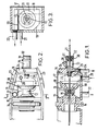
- the wire drawing device shown in Figures 1 to 3 comprises a structure 10 defining a chamber 11 in which is located a drawing die 12 which is clamped against the face of a die support 13 by a clamping nut 14 which extends through an end wall 15 forming part of the structure 10.
- the structure 10 has an end wall 16 and the chamber 11 can be closed by a loose cover 17 if desired.
- Located within the chamber 11 and extending between the end wall 15 and an intermediate wall 18 in which the die support 13 is mounted is a vertical plate 19 which is received in grooves provided in the walls 15 and 18 and which forms a weir.
- the structure 10 is provided with an inlet connection 20 through which a cooling liquid can flow into the chamber 11, the level of the liquid in the chamber 11 being determined by the weir plate 19 and is such as to submerge the drawing die 12 and the drawn wire 21.
- the cooling liquid after flowing over the weir plate 19 is drained through a drain conduit 22.
- an end cap 24 Mounted on the end wall 16 and held in position by clips 23 is an end cap 24 having an axial bore 25 and secured to the end cap 24 is a tube 26 which may be flexible if desired.
- the bore 25 is closed at one end by a wire guide 27 which seats against a flexible seal 28 and a flexible retainer 29 holds the guide 27 in position but allows the guide 27 to move so as to align itself on the wire axis.
- the end of the tube 26 is closed by a wire guide 30 provided in a mounting 31 and is retained in position by an end ring 32.
- the bore 25 and tube 26 form a chamber 33 to which is connected an outlet conduit 34.
- the conduit 34 is connected to a vacuum source so as to produce a sub-atmospheric pressure in the chamber 33.
- the cooling liquid will pass through the bore of the wire guide 27 with the wire 21 and the wire 21 thereby enters the chamber 33 in a wet condition. Because the pressure within the chamber 33 is below atmospheric pressure the vaporisation temperature of the cooling liquid is lowered and the liquid on the wire is evaporated which further cools and dries the wire 21. Advantage is also taken of the higher latent heat of vaporisation at the sub-atmospheric pressure. The sub-atmospheric pressure within the chamber 33 will cause air to flow into the chamber 33 through the guide 30 at high velocity which will wipe the wire 21 and sweeps any excess cooling fluid back into the chamber 33.
- the guide 27 has a diameter which will give a controlled flow of water from chamber 11 into chamber 33.
- the air and water in chamber 33 is evacuated from the chamber 33 by the conduit 34.
- the end cap 24 may be arranged to slide transversely to allow further alignment on the wire path. If the tube 26 is flexible further alignment is possible at the guide 30. In order to enable the wire 21 to be correctly set on the winding drum the path taken by the wire 21 from the outlet of the die 12 may have to be displaced from the axis of the die 12 and the adjustability of the guides 27, 30 allows this to be effected.
- the whole of the low pressure assembly can be made readily detachable to facilitate the threading of the wire 21 through the apparatus.
- a short length lead or point can be made on the wire 21 which can then be drawn through the die 12 for a short distance before the low pressure assembly is passed over the wire 21 and clipped in position.
- the low pressure assembly may be made to divide along a central longitudinal plane which is on the centre line to facilitate the threading of the wire 21.
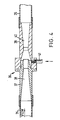
- a suitable apparatus for creating the sub-atmospheric pressure within the chamber 33 is shown in Figure 4 and comprises a conduit 35 provided with a venturi device 36 which consists of a portion 37 having a convergent passage 38 and a portion 39 having a convergent/divergent passage 40.
- Fluid is pumped through the conduit 35 in the direction indicated by the arrow and its kinetic energy is increased in the convergent passage 38 and a low pressure area at the convergent part of the convergent/divergent passage 40 is connected via a conduit 41 to the conduit 34 of the low pressure assembly of the apparatus shown in Figures 1 to 3.
- the fluid returns to approximately atmospheric pressure at the outlet of the divergent part of the convergent/ divergent passage 40.
- the convergent passage 38 and the convergent/divergent passage 40 can be of any desired cross-sectional shape, e.g. round or rectangular.
- FIG 5 illustrates a multi-die wire drawing apparatus, each wire drawing device 42 being similar to that shown in Figures 1 to 3 and the venturi device 36 being as shown in Figure 4.
- the inlet connection 20 of each wire drawing device 42 receives liquid coolant via conduits 43 and the drain conduits 22 of the devices 42 are connected to drain.
- the conduits 34 of the devices 42 are connected to the low pressure conduit 41 leading from the venturi device 36 and the fluid which is pumped by a pump 45 through the conduit 35 is withdrawn from a reservoir 46 and returned to the reservoir 46.
- the reservoir 46 has an overflow drain 47. If desired a secondary air vacuum pump 48 can be fitted to the conduit 41.
- FIG 6 shows a wire cooling device which is very similar to the liquid cooled wire drawing device shown in Figures 1 to 3 but in which the drawing die 12 is not provided.
- the weir is formed by a wall 49 which separates the chamber 11 from the drain conduit 22 and the wall 49 is provided with a wire guide 50 similar to guide 27.
- the device shown in Figure 6 can be used to cool any wire which has been heated.
- Figure 7 shows a low pressure device which is substantially identical to the apparatus shown in Figures 1 to 3 and used for drying and cooling a wire 21. Its function is the same as that described with reference to Figures 1 to 3.
- the guide 27 is fixed and held in place by a retainer 51 instead of by a flexible retainer 29.
- Figure 8 shows a wire cleaning device having at its upstream end a structure 52 having a chamber 53 separated from a drain conduit 54 by a wall 55 which forms a weir and which is provided with a wire guide 56.
- a low pressure apparatus which is substantially identical with that shown in Figure 7.
- Located between the upstream structure 52 and the low pressure apparatus are a plurality of baffles 57 provided in a cylinder 58.
- the flow of water through the orifices 60 purges the wire 21 to clean it.
- the water flows into the chamber 53 and then overflows the weir forming wall 55 and flows through the drain conduit 54.
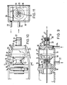
- FIG. 9 to 11 The embodiment shown in Figures 9 to 11 is similar to that described in Figures 1 to 3 and like parts are denoted by reference numerals corresponding to those shown in Figures 1 to 3.
- the drain conduit 22 is connected to a vacuum source so that a sub-atmospheric pressure is produced in the chamber 11 above the level of the liquid coolant and the liquid coolant is supplied through the conduit 34 so that the chamber 33 also contains the liquid coolant.
- the bath of liquid coolant is at a sub-atmospheric pressure and therefore air will flow into the chamber 33 through the guide 30 at high velocity which will wipe the wire 21.
- the cover 17 in this embodiment is sealed to prevent air flow into the apparatus between the cover 17 and the structure forming the chamber 11.
- the guide 27, seal 28 and retainer 29 are dispensed within this embodiment.
Landscapes
- Engineering & Computer Science (AREA)
- Mechanical Engineering (AREA)
- Drying Of Solid Materials (AREA)
- Metal Extraction Processes (AREA)
- Blast Furnaces (AREA)
- Processing And Handling Of Plastics And Other Materials For Molding In General (AREA)
- Cleaning And De-Greasing Of Metallic Materials By Chemical Methods (AREA)
- Extrusion Moulding Of Plastics Or The Like (AREA)
Claims (9)
Priority Applications (1)
| Application Number | Priority Date | Filing Date | Title |
|---|---|---|---|
| AT83301995T ATE21637T1 (de) | 1982-05-18 | 1983-04-08 | Vorrichtung zum kuehlen, trocknen und reinigen von langgestrecktem material. |
Applications Claiming Priority (2)
| Application Number | Priority Date | Filing Date | Title |
|---|---|---|---|
| GB8214381 | 1982-05-18 | ||
| GB8214381 | 1982-05-18 |
Publications (2)
| Publication Number | Publication Date |
|---|---|
| EP0094740A1 EP0094740A1 (fr) | 1983-11-23 |
| EP0094740B1 true EP0094740B1 (fr) | 1986-08-27 |
Family
ID=10530417
Family Applications (1)
| Application Number | Title | Priority Date | Filing Date |
|---|---|---|---|
| EP83301995A Expired EP0094740B1 (fr) | 1982-05-18 | 1983-04-08 | Dispositif pour le refroidissement, le séchage et le nettoyage de matériel allongé |
Country Status (6)
| Country | Link |
|---|---|
| US (1) | US4739640A (fr) |
| EP (1) | EP0094740B1 (fr) |
| JP (1) | JPS5927710A (fr) |
| AT (1) | ATE21637T1 (fr) |
| DE (1) | DE3365564D1 (fr) |
| ZA (1) | ZA832579B (fr) |
Families Citing this family (9)
| Publication number | Priority date | Publication date | Assignee | Title |
|---|---|---|---|---|
| US5823039A (en) * | 1995-02-07 | 1998-10-20 | Noge Electric Industries Co., Ltd. | Apparatus for drawing wire using a heated drawing die and cooling device |
| DE19817088C2 (de) * | 1998-04-17 | 2000-02-17 | Ecoform Umformtechnik Gmbh | Verfahren und Vorrichtung zum Beschichten und Umformen von strangförmigem metallischem Umformgut mittels Ziehen |
| DE10058369C1 (de) * | 2000-11-24 | 2002-02-14 | Rainer Menge | Drahtkühleinrichtung |
| US6851293B2 (en) * | 2003-05-27 | 2005-02-08 | Alcan International Limited | Wire reduction device |
| WO2014090813A1 (fr) | 2012-12-12 | 2014-06-19 | Sandvik Materials Technology Deutschland Gmbh | Machine et procédé de traitement pour travailler l'extrémité d'un tube |
| DE102013102704A1 (de) | 2013-03-18 | 2014-09-18 | Sandvik Materials Technology Deutschland Gmbh | Verfahren zum Herstellen eines Stahlrohres mit Reinigung der Rohrinnenwand |
| DE102013102703A1 (de) * | 2013-03-18 | 2014-09-18 | Sandvik Materials Technology Deutschland Gmbh | Verfahren zum Herstellen eines Stahlrohres mit Reinigung der Rohraußenwand |
| CN103447331A (zh) * | 2013-08-30 | 2013-12-18 | 无锡常欣科技股份有限公司 | 封闭式压力水冷模盒 |
| IT201900012837A1 (it) * | 2019-07-25 | 2021-01-25 | Vassena Filiere S R L | Attrezzo per la trafilatura a freddo di un filo metallico migliorato. |
Family Cites Families (8)
| Publication number | Priority date | Publication date | Assignee | Title |
|---|---|---|---|---|
| US2638207A (en) * | 1947-11-17 | 1953-05-12 | Engineering Res Associates Inc | Method and apparatus for forming wire and the like |
| US3605466A (en) * | 1969-11-26 | 1971-09-20 | Frank B Kilcoin | Apparatus for drawing metal wire and the like and the method thereof |
| DE2345090A1 (de) * | 1972-09-08 | 1974-03-14 | M P S P A Meccanica Di Prec E | Verfahren und vorrichtung zur schmierung von drahtziehsteinen od. dgl |
| FR2234053B1 (fr) * | 1973-06-23 | 1978-08-11 | Kobe Steel Ltd | |
| FR2332821A1 (fr) * | 1975-11-25 | 1977-06-24 | Dev Fil Metallique | Trefileuse pour fils metalliques |
| DD128482B1 (de) * | 1976-09-29 | 1981-04-29 | Armin Schubert | Verfahren und einrichtung zum trocknen von durchlaufendem draht |
| JPS5524791A (en) * | 1978-08-12 | 1980-02-22 | Kobe Steel Ltd | Apparatus for forced lubrication and solid drawing |
| DE2843449A1 (de) * | 1978-10-05 | 1980-04-10 | Juergen Volkmann | Verfahren und vorrichtung zum entfernen oder dosiertem vermindern adhaesiver fluessigkeitsfilme auf harten oberflaechen |
-
1983
- 1983-04-08 AT AT83301995T patent/ATE21637T1/de not_active IP Right Cessation
- 1983-04-08 EP EP83301995A patent/EP0094740B1/fr not_active Expired
- 1983-04-08 DE DE8383301995T patent/DE3365564D1/de not_active Expired
- 1983-04-13 ZA ZA832579A patent/ZA832579B/xx unknown
- 1983-05-17 JP JP58087384A patent/JPS5927710A/ja active Pending
-
1985
- 1985-06-28 US US06/750,759 patent/US4739640A/en not_active Expired - Fee Related
Also Published As
| Publication number | Publication date |
|---|---|
| ZA832579B (en) | 1984-01-25 |
| EP0094740A1 (fr) | 1983-11-23 |
| DE3365564D1 (en) | 1986-10-02 |
| JPS5927710A (ja) | 1984-02-14 |
| US4739640A (en) | 1988-04-26 |
| ATE21637T1 (de) | 1986-09-15 |
Similar Documents
| Publication | Publication Date | Title |
|---|---|---|
| EP0094740B1 (fr) | Dispositif pour le refroidissement, le séchage et le nettoyage de matériel allongé | |
| US4440698A (en) | Apparatus for ensuring heat exchange between a gas flow and a heat exchanger | |
| JPH04228448A (ja) | ガラスファイバの冷却方法および装置 | |
| US2684728A (en) | Apparatus for removing air from viscose solution | |
| SE450467B (sv) | Anordning for att kontinuerligt kyla en uppvermd metallplat | |
| US4394142A (en) | Water spray cooler | |
| JP3364818B2 (ja) | 流下液膜式蒸発器及び該流下液膜式蒸発器を備えたターボ冷凍機 | |
| US4741113A (en) | Air wiper | |
| US4194950A (en) | Liquid purifying apparatus | |
| US4442049A (en) | Apparatus for ensuring heat exchange between a gas flow and a heat exchanger | |
| US3009257A (en) | Integrated squeegee-air dryer | |
| EP0032430A1 (fr) | Appareil permettant d'appliquer des produits chimiques liquides à une bande en déplacement | |
| JPH07310699A (ja) | 気体を用いて液体を移送する方法及び装置 | |
| EP0052009A2 (fr) | Dispositif pour assurer l'échange de chaleur entre un courant de gaz et un échangeur de chaleur | |
| IL22299A (en) | Devices for use in evaporation processes | |
| IL99673A (en) | Condenser and method for condensing Ed | |
| RU2012174C1 (ru) | Электронное устройство | |
| SU994891A1 (ru) | Испарительный конденсатор | |
| EP4286772B1 (fr) | Évaporateur, systeme hvacr l'utilisant, et methode de fonctionnement d'un evaporateur | |
| SU1039530A1 (ru) | Аппарат дл улавливани аэрозольных частиц | |
| US3392267A (en) | Heating unit for fiber stretching installations | |
| RU853U1 (ru) | Вентиляторная градирня | |
| SU1335779A1 (ru) | Устройство дл обработки воздуха в салоне транспортного средства | |
| JPS58162717A (ja) | ラジエ−タの急冷装置 | |
| SU1041822A2 (ru) | Тепломассообменный аппарат |
Legal Events
| Date | Code | Title | Description |
|---|---|---|---|
| PUAI | Public reference made under article 153(3) epc to a published international application that has entered the european phase |
Free format text: ORIGINAL CODE: 0009012 |
|
| AK | Designated contracting states |
Designated state(s): AT BE CH DE FR GB IT LI LU NL SE |
|
| 17P | Request for examination filed |
Effective date: 19840509 |
|
| ITF | It: translation for a ep patent filed | ||
| GRAA | (expected) grant |
Free format text: ORIGINAL CODE: 0009210 |
|
| AK | Designated contracting states |
Kind code of ref document: B1 Designated state(s): AT BE CH DE FR GB IT LI LU NL SE |
|
| PG25 | Lapsed in a contracting state [announced via postgrant information from national office to epo] |
Ref country code: AT Effective date: 19860827 |
|
| REF | Corresponds to: |
Ref document number: 21637 Country of ref document: AT Date of ref document: 19860915 Kind code of ref document: T |
|
| REF | Corresponds to: |
Ref document number: 3365564 Country of ref document: DE Date of ref document: 19861002 |
|
| ET | Fr: translation filed | ||
| PG25 | Lapsed in a contracting state [announced via postgrant information from national office to epo] |
Ref country code: SE Effective date: 19870409 |
|
| PG25 | Lapsed in a contracting state [announced via postgrant information from national office to epo] |
Ref country code: LU Free format text: LAPSE BECAUSE OF NON-PAYMENT OF DUE FEES Effective date: 19870430 Ref country code: LI Effective date: 19870430 Ref country code: CH Effective date: 19870430 |
|
| PLBE | No opposition filed within time limit |
Free format text: ORIGINAL CODE: 0009261 |
|
| STAA | Information on the status of an ep patent application or granted ep patent |
Free format text: STATUS: NO OPPOSITION FILED WITHIN TIME LIMIT |
|
| 26N | No opposition filed | ||
| PG25 | Lapsed in a contracting state [announced via postgrant information from national office to epo] |
Ref country code: NL Effective date: 19871101 |
|
| NLV4 | Nl: lapsed or anulled due to non-payment of the annual fee | ||
| REG | Reference to a national code |
Ref country code: CH Ref legal event code: PL |
|
| PG25 | Lapsed in a contracting state [announced via postgrant information from national office to epo] |
Ref country code: GB Effective date: 19890408 |
|
| PG25 | Lapsed in a contracting state [announced via postgrant information from national office to epo] |
Ref country code: BE Effective date: 19890430 |
|
| BERE | Be: lapsed |
Owner name: HI-DRAW MACHINERY LTD Effective date: 19890430 |
|
| GBPC | Gb: european patent ceased through non-payment of renewal fee | ||
| PG25 | Lapsed in a contracting state [announced via postgrant information from national office to epo] |
Ref country code: FR Free format text: LAPSE BECAUSE OF NON-PAYMENT OF DUE FEES Effective date: 19891228 |
|
| PG25 | Lapsed in a contracting state [announced via postgrant information from national office to epo] |
Ref country code: DE Effective date: 19900103 |
|
| REG | Reference to a national code |
Ref country code: FR Ref legal event code: ST |
|
| EUG | Se: european patent has lapsed |
Ref document number: 83301995.3 Effective date: 19880906 |