EP0094749A2 - Contrôle du débit sanguin capillaire - Google Patents
Contrôle du débit sanguin capillaire Download PDFInfo
- Publication number
- EP0094749A2 EP0094749A2 EP83302276A EP83302276A EP0094749A2 EP 0094749 A2 EP0094749 A2 EP 0094749A2 EP 83302276 A EP83302276 A EP 83302276A EP 83302276 A EP83302276 A EP 83302276A EP 0094749 A2 EP0094749 A2 EP 0094749A2
- Authority
- EP
- European Patent Office
- Prior art keywords
- cervical
- blood flow
- vaginal
- capillary blood
- support
- Prior art date
- Legal status (The legal status is an assumption and is not a legal conclusion. Google has not performed a legal analysis and makes no representation as to the accuracy of the status listed.)
- Withdrawn
Links
Images

Classifications
-
- A—HUMAN NECESSITIES
- A61—MEDICAL OR VETERINARY SCIENCE; HYGIENE
- A61B—DIAGNOSIS; SURGERY; IDENTIFICATION
- A61B5/00—Measuring for diagnostic purposes; Identification of persons
- A61B5/145—Measuring characteristics of blood in vivo, e.g. gas concentration or pH-value ; Measuring characteristics of body fluids or tissues, e.g. interstitial fluid or cerebral tissue
- A61B5/1455—Measuring characteristics of blood in vivo, e.g. gas concentration or pH-value ; Measuring characteristics of body fluids or tissues, e.g. interstitial fluid or cerebral tissue using optical sensors, e.g. spectral photometrical oximeters
- A61B5/1464—Measuring characteristics of blood in vivo, e.g. gas concentration or pH-value ; Measuring characteristics of body fluids or tissues, e.g. interstitial fluid or cerebral tissue using optical sensors, e.g. spectral photometrical oximeters specially adapted for foetal tissue
-
- A—HUMAN NECESSITIES
- A61—MEDICAL OR VETERINARY SCIENCE; HYGIENE
- A61B—DIAGNOSIS; SURGERY; IDENTIFICATION
- A61B5/00—Measuring for diagnostic purposes; Identification of persons
- A61B5/03—Measuring fluid pressure within the body other than blood pressure, e.g. cerebral pressure ; Measuring pressure in body tissues or organs
- A61B5/033—Uterine pressure
- A61B5/035—Intra-uterine probes therefor
-
- A—HUMAN NECESSITIES
- A61—MEDICAL OR VETERINARY SCIENCE; HYGIENE
- A61B—DIAGNOSIS; SURGERY; IDENTIFICATION
- A61B5/00—Measuring for diagnostic purposes; Identification of persons
- A61B5/145—Measuring characteristics of blood in vivo, e.g. gas concentration or pH-value ; Measuring characteristics of body fluids or tissues, e.g. interstitial fluid or cerebral tissue
- A61B5/14542—Measuring characteristics of blood in vivo, e.g. gas concentration or pH-value ; Measuring characteristics of body fluids or tissues, e.g. interstitial fluid or cerebral tissue for measuring blood gases
Definitions
- the present invention relates to the monitoring of capillary blood flow in a woman's cervix and vagina for the diagnosis of various physiological conditions.
- uterine artery blood flow is the most important single factor in fetal growth and development. In situations where it is markedly compromised as the consequence of overt maternal cardiovascular disease, the fetus may be undergrown, or even die. In the human patient, it is not possible to obtain an accurate measurement of uterine blood flow directly with non-invasive techniques. However, the uterine artery supplies not only the corpus of the uterus, but also the cervix uteri and the vagina through its vaginal branches. Hence, it is possible to determine to a large extent, the status of uterine artery blood flow by evaluation of cervical and capillary blood flow.
- uterine artery blood flow is of importance during gestation to determine if it is adequate. It may be compromised by maternal cardiovascular disease, diabetes melletus, toxemia of pregnancy and other diseases. If the uterine artery flow is diminished, maternal treatment would be re-evaluated to find a more efficacious treatment. In circumstances where it is compromised to the point where intact fetal survival is threatened, the gestation would be terminated to save the fetus from irreversible damage or death.
- uterine contractions constitute an additional stress to the fetus, since each contraction decreases blood flow to the placenta. Hence, it is doubly important at these times to measure uterine blood flow.
- Another concern during labor is maternal hypotension as a consequence of maternal position and/or conduction anesthesia. The presence of hypotension adds an additional fetal hazard.
- the woman's uterus and vagina are both supplied with blood by the uterine artery.
- Capillary blood flow in the cervix and vagina is related directly to uterine artery flow.
- the ability to monitor continuously such capillary flow provides the potential for acquiring data of clinical significance e.g., uteroplacental insufficiency, the effect of uterine contraction on uterine blood flow.
- Maternal hypotension can result from blockage of the veins returning blood to the heart from the pelvis as a result of pressure exerted by the uterus. This is apt to occur especially in the case of the patient with conduction anesthesia, inasmuch as her blood tends to pool in the pelvis.
- the reduced input of blood to the heart as a consequence of these conditions leads to reduced cardiac output and consequent hypotension. This condition is potentially dangerous to the fetus due to the consequent reduction in the flow of oxygenated blood to the uterus.
- Circulatory conditions specific to the uterus must be distinguished clinically from those affecting pelvic blood flow more generally. Therefore, to accurately diagnose the condition of the mother and the fetus in the intrapartum, and in the late antepartum, it is necessary both to obtain an indication of uterine blood flow, as well as a more general indication of pelvic blood flow. Such a capability is provided by the simultaneous monitoring of cervical capillary blood flow and vaginal capillary blood flow.
- a method is provided of evaluating the physiological condition of a woman, comprising the steps of: producing a first signal representative of capillary blood flow in the woman's cervix; producing a second signal representative of capillary blood flow in the woman's vagina; and comparing the first and second signals.
- a further object is to provide such devices which will avoid undue irritation of vaginal and cervical tissues.
- a device for use in monitoring cervical and/or vaginal capillary blood flow.
- the device comprises a support adapted to be held between the vaginal wall and the cervical wall of a woman, and means for sensing capillary blood flow.
- the sensing means is positioned on the support to contact one of the cervical wall and the vaginal wall for sensing capillary blood flow therein.
- this support is adapted to be expanded when placed between the cervical wall and the vaginal wall such that it presses against and is held by at least one of the vaginal and cervical walls. It is thus possible to provide a device which is sized for ease of placement between the vaginal and cervical walls, but which thereafter expands to fit snuggly therebetween.
- the support is capable of being modified at the time of clinical use to conform to a woman's cervix. Accordingly, the embodiment being adaptable to various cervices, it is not necessary to manufacture a large variety of devices to accommodate these variations.
- the device 10 for use in monitoring cervical and/or vaginal capillary blood flow is illustrated.
- the device 10 includes a support 12 adapted to be held between the vaginal wall and the cervical wall of a woman.
- the support 12 has a toroidal shape and is dimensioned accordingly for placement between the vaginal and cervical walls.
- the toroidal support 12 extends at least about two thirds of a circle.
- Three capillary blood flow sensors 14a, 14b and 14c are located on an inner, concave surface 16 of the support 12 at intervals of about one third of a circle for contacting the cervical wall to sense capillary blood flow therein.
- Three additional capillary blood flow sensors 14d, 14e and 14f are positioned on an outer, convex wall 18 of the support 12 at angular intervals of about one third of a circle for contacting the vaginal wall to sense capillary blood flow therein. Sensors 14a-f are described in greater detail below in connection with Figures 3 and 4.
- the support 12 includes a cushion 20 made of a sponge material which is non-reactive and may be, for example, silicone, dacron or nylon.
- the cushion 20, therefore, is adapted to absorb fluids and consequently expands as the fluids are accumulated. Accordingly, when the device 10 is placed between the cervical wall and the vaginal wall, vaginal fluids are absorbed by the cushion 20 causing it to expand and press against the vaginal and cervical walls, such that it is held snuggly therebetween. At the same time, the sponge cushion 20 presses softly against the tissues in order to avoid undue irritation thereof.
- the support 12 also includes a form-sustaining spine 22 embodied in the cushion 20 such that it does not come in contact with the bodily tissues.
- Spine 22 is made of a bendable material, so that at the time of clinical use, the device 10 may be expanded radially or contracted radially to accomodate the size of a particular patient's cervix.
- a modified device 10' for use in monitoring cervical and/or vaginal capillary blood flow.
- the device 10' includes an expandable bladder 23 disposed within cushion 20 and adapted to be expanded when inflated with fluid, such as saline solution.
- a filling tube 25 communicates with bladder 23 at a first end of tube 25 and extends therefrom outwardly of cushion 20 through an aperture 27 therein.
- Tube 25 provides a means for inflating the bladder 23 within cushion 20 so that the cusion may be expanded to fit snugly between the cervical wall and the vaginal wall.
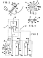
- Figure 2 illustrates a manner in which the devices of Figures 1, and 1A may be positioned between the cervical wall 60 and the vaginal wall 62 of a woman.
- Device 10 or 10' is introduced through the vagina and pressed upwardly between the cervical wall 60 and vaginal wall 62 along the posterior and lateral sides thereof.
- the sensors 14a-c on the inner concave surface of the devices 10' and 10 face toward and are pressed against the cervical wall for monitoring capillary blood flow therein
- the sensors 14d-f positioned on the outer, convex wall of the devices 10 and 10' face toward and are pressed against the vaginal wall 62 to sense capillary blood flow therein.
- the wires 34 lead through the vagina and outwardly thereof for coupling to monitoring circuitry, such as that described below in connection with Figure 5.
- the tube 25 leads through the vagina and outwardly thereof to permit the bladder to be inflated so that the device 10' fits snugly between the cervical wall 60 and the vaginal wall 62.
- Figures IB, 1C and 1D illustrate a device 100 for use in monitoring several different physiological parameters during labor, namely, cervical dilatation, intrauterine pressure, maternal ECG, and cervical capillary blood flow.
- the ability to monitor cervical capillary blood flow is provided by a sensor 14 corresponding to that described below in connection with Figures 3 and 4.
- the device 100 includes two tubes 102 and 104 in side-by-side relationship and a sponge 114 covering the distal ends of tubes 102 and 104.
- a cover 106 is disposed over the sponge ll4 and a portion of tubes 102 and 104 extending in a proximal direction from sponge 114.
- Cover 106 has a plurality of pinholes 116 therethrough adjacent its distal end to permit uterine fluids to fill the sponge 114.
- Sensor 14 is affixed to the sponge 114 adjacent its proximal end and projects outwardly of cover 106.
- Device 100 is adapted to be positioned between a fetal presenting part and the cervix during labor. Sensor 14 is disposed to face the cervical wall for monitoring capillary blood flow therein.
- the wires from sensor 14 pass through tube 104 to its proximal end which is disposed outside the vagina for coupling the wires to monitoring apparatus. After the device 100 is in place between the presenting part and the cervical wall, uterine fluids fill the sponge ll4 through pinholes ll6.
- the sensor 14 includes six infrared transmitters 24 arranged about and spaced from a photoresponsive element 26.
- the infrared transmitters 24 and the photoresponsive element 26 are embedded in a plastic base 28 and protrude through a surface 30 of the base 28 which is positioned to face one of the cervical and vaginal walls when the sensor 14 is positioned in the devices 10 and 10 1 .
- the protrusion of the transmitter 24 and the element 26 through the surface 30 aids in minimizing the effects of forces tending to separate the sensor from the tissues since they are pressed into the tissues.
- Transmitters 24 are angled inwardly of the sensor 14 to transmit infrared radiation to a point in the tissues beneath the element 26.
- the sensor 14 also includes an annular guard ring 32 defining the lateral border of the base 28.
- the guard ring 32 is adapted to press against the tissue and block the transmission of any surface waves in the tissue from the surface thereof adjacent the transmitters 24 and the element 26, since such waves may tend to temporarily separate the transmitters 24 and the element 26 from the tissue, introducing artifacts into the signal produced by the sensor 14.
- FIG. 5 a schematic diagram of a system 40 for monitoring cervical and/or vaginal capillary blood flow using the devices of Figures 1 and lA, is illustrated schematically.
- the transmitters 24 include respective light emitting diodes (the six transmitters being shown schematically as two diodes) connected in a single series arrangement having a first terminal 42 coupled through a wire 34a to the equipment ground of a blood flow signal producing circuit 44.
- a wire 34b couples the opposite end of the series connected diodes to a second terminal 46 to receive an illuminating voltage.
- the illuminating voltage is provided as a pulse train, such that the transmitters 24 produce pulses of infrared radiation 48 directed into the adjacent tissue.
- Reflected portions 50 of the pulses 48 are incident on the photoresponsive element 26, provided in the form of a phototransistor, thus to render the collector-to-emitter circuit thereof conductive in proportion to the incident radiation 50.
- the emitter of transistor 26 is connected to equipment ground at first terminal 42 and its collector is connected to a respective one of three input terminals of the circuit 44 through a wire 34c.
- Each of the three input terminals of the circuit 44 is AC coupled through a respective capacitor 52 to a respective input terminal of an adding circuit 54.
- Adding circuit 54 provides an output signal at an output terminal 56 thereof, the output signal being proportional to the sum of the input signals received by the adding circuit 54, and therefore, representative of their average value.
- This signal provided on terminal 56 may then be displayed, for example, on the screen of an non-fade oscilloscope or recorded by means of a strip chart recorder for clinical analysis, or stored in memory for future clinical analysis.
- Two systems of the type illustrated schematically in Figure 5 may be provided, a first system for providing a signal representative of capillary blood flow in the cervix which receives input signals from sensors 14a-l4c, and a second system for producing a signal representative of capillary blood flow in the vaginal wall and therefore, receiving input signals from the sensors 14d-f. Accordingly, two signals will be produced, one representative of capillary blood flow in the cervix and the other representing capillary blood flow in the vagina. These signals may be displayed and/or processed so they may be compared by the clinician to obtain valuable diagnostic information. In accordance with one method of comparison, the two signals are displayed with respect to a common time base.
- a third signal representative of differences between the first and second signals is produced to provide the clinician with a separate signal representing a comparison of the first two signals.
- This third signal is produced in accordance with one advantageous method by subtracting one of the first and second signals form the other.
- these signals provide a measure of the similarities and differences between capillary blood flow patterns in the cervix and in the vagina, in order to aid in the diagnosis of conditions specific to the uterus as well as those affecting pelvic circulation in general.
- this method is useful for diagnosing conditions such as premature labor and utero-placental insufficiency, indicated by reduced circulation in the uterus as compared to pelvic circulation in general.
- enhanced capillary blood flow in the cervix compared with capillary blood flow in the vagina serves potentially to indicate the time of ovulation when compared to the difference between cervical capillary blood flow and vaginal capillary blood flow at other times during the menstrual circle.
- a further application of the present invention is to provide a comparison of capillary blood flow in the cervix and vagina with capillary blood flow in the woman's forehead at the anastomosis of the supratrochlear branches of the ophthalmic artery, the latter representing the woman's general circulatory well being.
- the capillary blood flow in the woman's forehead may be obtained by pressing a sensor of the type shown in Figures 3 and 4 against the forehead and maintaining the sensor so positioned with the use of a head strap.
- the capillary blood flow signal is produced using a system such as that illustrated in Figure 5.
- a comparison of the first and second signals is produced by any of the methods described above for comparing the cervical capillary blood flow signal with the vaginal capillary blood flow signal.
- This method is particularly useful for comparing pelvic blood flow patterns with a blood flow pattern indicative of the woman's overall circulatory well being, and is, therefore, useful for detecting the pooling of blood in the pelvis due to the effects of conduction anesthesia, which may contribute to maternal hypotension.
- cervical capillary blood flow With a blood flow pattern indicative of the woman's overall circulatory condition, the occurence of contractions indicative of premature labor are indicated.
- Other conditions specific to the uterus such as ovulation, and in the case of a pregnant woman, utero-placental insufficiency may also be indicated.
Landscapes
- Health & Medical Sciences (AREA)
- Life Sciences & Earth Sciences (AREA)
- Physics & Mathematics (AREA)
- Molecular Biology (AREA)
- Animal Behavior & Ethology (AREA)
- Pathology (AREA)
- Engineering & Computer Science (AREA)
- Biomedical Technology (AREA)
- Heart & Thoracic Surgery (AREA)
- Medical Informatics (AREA)
- Veterinary Medicine (AREA)
- Surgery (AREA)
- Biophysics (AREA)
- General Health & Medical Sciences (AREA)
- Public Health (AREA)
- Optics & Photonics (AREA)
- Pediatric Medicine (AREA)
- Spectroscopy & Molecular Physics (AREA)
- Hematology (AREA)
- Measuring Pulse, Heart Rate, Blood Pressure Or Blood Flow (AREA)
- Measurement Of The Respiration, Hearing Ability, Form, And Blood Characteristics Of Living Organisms (AREA)
- Investigating Or Analysing Biological Materials (AREA)
- Measuring And Recording Apparatus For Diagnosis (AREA)
Applications Claiming Priority (2)
| Application Number | Priority Date | Filing Date | Title |
|---|---|---|---|
| US371370 | 1982-04-23 | ||
| US06/371,370 US4541439A (en) | 1982-04-23 | 1982-04-23 | Monitoring of capillary blood flow |
Publications (2)
| Publication Number | Publication Date |
|---|---|
| EP0094749A2 true EP0094749A2 (fr) | 1983-11-23 |
| EP0094749A3 EP0094749A3 (fr) | 1984-04-11 |
Family
ID=23463707
Family Applications (1)
| Application Number | Title | Priority Date | Filing Date |
|---|---|---|---|
| EP83302276A Withdrawn EP0094749A3 (fr) | 1982-04-23 | 1983-04-21 | Contrôle du débit sanguin capillaire |
Country Status (5)
| Country | Link |
|---|---|
| US (1) | US4541439A (fr) |
| EP (1) | EP0094749A3 (fr) |
| JP (1) | JPS58192530A (fr) |
| DK (1) | DK179783A (fr) |
| GR (1) | GR78527B (fr) |
Cited By (9)
| Publication number | Priority date | Publication date | Assignee | Title |
|---|---|---|---|---|
| EP0135840A3 (fr) * | 1983-08-30 | 1986-06-11 | Nellcor Incorporated | Oxymètre à usage périnatologique |
| US4938218A (en) * | 1983-08-30 | 1990-07-03 | Nellcor Incorporated | Perinatal pulse oximetry sensor |
| US5024226A (en) * | 1989-08-17 | 1991-06-18 | Critikon, Inc. | Epidural oxygen sensor |
| US5109849A (en) * | 1983-08-30 | 1992-05-05 | Nellcor, Inc. | Perinatal pulse oximetry sensor |
| US5228440A (en) * | 1990-08-22 | 1993-07-20 | Nellcor, Inc. | Fetal pulse oximetry apparatus and method of use |
| US5551424A (en) * | 1990-05-29 | 1996-09-03 | Phox Medical Optics, Inc. | Fetal probe apparatus |
| EP0726730A4 (fr) * | 1993-10-29 | 1997-03-26 | Raul Artal | Dispositif et procede de controle permettant de detecter le travail avant terme |
| US5839439A (en) * | 1995-11-13 | 1998-11-24 | Nellcor Puritan Bennett Incorporated | Oximeter sensor with rigid inner housing and pliable overmold |
| WO1999035968A1 (fr) * | 1998-01-13 | 1999-07-22 | Urometrics, Inc. | Procede et dispositif de surveillance de l'excitation sexuelle chez la femme |
Families Citing this family (16)
| Publication number | Priority date | Publication date | Assignee | Title |
|---|---|---|---|---|
| US6039701A (en) * | 1996-09-05 | 2000-03-21 | Ob Inovations, Inc. | Method and apparatus for monitoring cervical diameter |
| US5876357A (en) * | 1997-11-20 | 1999-03-02 | Labor Control System (L.C.S.) Ltd. | Uterine cervix dilation, effacement, and consistency monitoring system |
| IL126723A0 (en) * | 1998-10-22 | 1999-08-17 | Medoc Ltd | Vaginal probe and method |
| US6997879B1 (en) * | 2002-07-09 | 2006-02-14 | Pacesetter, Inc. | Methods and devices for reduction of motion-induced noise in optical vascular plethysmography |
| US7738935B1 (en) | 2002-07-09 | 2010-06-15 | Pacesetter, Inc. | Methods and devices for reduction of motion-induced noise in pulse oximetry |
| US7174774B2 (en) * | 2002-08-30 | 2007-02-13 | Kimberly-Clark Worldwide, Inc. | Method and apparatus of detecting pooling of fluid in disposable or non-disposable absorbent articles |
| JP5328159B2 (ja) | 2005-03-01 | 2013-10-30 | セルカコア・ラボラトリーズ・インコーポレーテッド | 多波長センサ発光体 |
| ITMI20051328A1 (it) * | 2005-07-13 | 2007-01-14 | Agristudio Srl | Apparecchiatura e procedimento per il rilevamento dello stato riproduttivo in particolare dello stato estrale di un mammifero |
| US8282612B1 (en) | 2008-03-07 | 2012-10-09 | Denise H. Miller | Methods and devices for intrauterine absorption |
| US20100004518A1 (en) | 2008-07-03 | 2010-01-07 | Masimo Laboratories, Inc. | Heat sink for noninvasive medical sensor |
| US8630691B2 (en) | 2008-08-04 | 2014-01-14 | Cercacor Laboratories, Inc. | Multi-stream sensor front ends for noninvasive measurement of blood constituents |
| US9078786B1 (en) | 2012-10-19 | 2015-07-14 | Denise H. Miller | Methods and devices for collecting body fluids |
| JP6307328B2 (ja) * | 2014-04-07 | 2018-04-04 | 浜松ホトニクス株式会社 | メタマテリアル光学部材、光検出装置、レーザ励起光源及び計測装置 |
| EP3531923B1 (fr) | 2016-10-27 | 2021-07-28 | Ava AG | Système et procédé de surveillance non invasive d'oestrogène |
| KR20220129033A (ko) | 2020-01-13 | 2022-09-22 | 마시모 코오퍼레이션 | 생리학적 파라미터 모니터링 기능이 있는 웨어러블 디바이스 |
| EP4370022A1 (fr) | 2021-07-13 | 2024-05-22 | Masimo Corporation | Dispositif portatif avec surveillance de paramètre physiologique |
Family Cites Families (15)
| Publication number | Priority date | Publication date | Assignee | Title |
|---|---|---|---|---|
| NL7016262A (fr) * | 1970-11-06 | 1972-05-09 | ||
| US3739640A (en) * | 1971-02-08 | 1973-06-19 | Wisconsin Alumni Res Found | Electromagnetic flowmeters for blood or other conductive fluids |
| US3717031A (en) * | 1971-02-22 | 1973-02-20 | Univ California | Three electrode flow meter |
| US3769974A (en) * | 1971-06-29 | 1973-11-06 | Martin Marietta Corp | Blood pulse measuring employing reflected red light |
| US3945250A (en) * | 1974-04-19 | 1976-03-23 | Statham Instruments, Inc. | Flow transducers |
| FR2365327A1 (fr) * | 1976-09-28 | 1978-04-21 | Remih Harry | Dispositif pour l'entrainement controle et la mesure de la tension des muscles vaginaux |
| DE2819128A1 (de) * | 1978-04-29 | 1979-11-08 | Raben Ralph Holger Dr | Verfahren und vorrichtung zum feststellen der durchblutung eines organs |
| US4312361A (en) * | 1979-04-20 | 1982-01-26 | Codman And Shurtleff, Inc. | Pressure monitoring system for electrofluidic sensing devices |
| EP0042405B1 (fr) * | 1979-12-27 | 1984-07-25 | Villamosipari Kutato Intezet | Appareil de mesure de la pression sanguine d'animaux de laboratoire |
| DE3029234A1 (de) * | 1980-08-01 | 1982-04-01 | Schloemann-Siemag AG, 4000 Düsseldorf | Metallstrangpresse zum indirekten und direkten verpressen von metallen mit einer mit dem aufnehmerhalter verbundenen vorrichtung zum abtrennen des pressrestes und zum auswechseln von matrizen |
| US4300570A (en) * | 1980-04-24 | 1981-11-17 | The Medical College Of Wisconsin, Inc. | Diagnostic method |
| GB2076963B (en) * | 1980-05-29 | 1984-04-11 | Mott Godfrey Thomas | Blood flow monitor |
| NL8005145A (nl) * | 1980-09-12 | 1982-04-01 | Tno | Inrichting voor de indirekte, niet-invasieve, continue meting van de bloeddruk. |
| US4332258A (en) * | 1980-09-29 | 1982-06-01 | Asajiro Arai | Portable pulse meter |
| US4369773A (en) * | 1980-11-05 | 1983-01-25 | Milos Chvapil | Contraceptive sponge - diaphragm bilayer |
-
1982
- 1982-04-23 US US06/371,370 patent/US4541439A/en not_active Expired - Fee Related
-
1983
- 1983-04-12 GR GR71066A patent/GR78527B/el unknown
- 1983-04-21 EP EP83302276A patent/EP0094749A3/fr not_active Withdrawn
- 1983-04-22 DK DK179783A patent/DK179783A/da not_active Application Discontinuation
- 1983-04-22 JP JP58072038A patent/JPS58192530A/ja active Pending
Cited By (13)
| Publication number | Priority date | Publication date | Assignee | Title |
|---|---|---|---|---|
| EP0135840A3 (fr) * | 1983-08-30 | 1986-06-11 | Nellcor Incorporated | Oxymètre à usage périnatologique |
| US4938218A (en) * | 1983-08-30 | 1990-07-03 | Nellcor Incorporated | Perinatal pulse oximetry sensor |
| US5109849A (en) * | 1983-08-30 | 1992-05-05 | Nellcor, Inc. | Perinatal pulse oximetry sensor |
| US5024226A (en) * | 1989-08-17 | 1991-06-18 | Critikon, Inc. | Epidural oxygen sensor |
| US5127407A (en) * | 1989-08-17 | 1992-07-07 | Critikon, Inc. | Epidural oxygen sensor |
| US5551424A (en) * | 1990-05-29 | 1996-09-03 | Phox Medical Optics, Inc. | Fetal probe apparatus |
| US5228440A (en) * | 1990-08-22 | 1993-07-20 | Nellcor, Inc. | Fetal pulse oximetry apparatus and method of use |
| US5743260A (en) * | 1990-08-22 | 1998-04-28 | Nellcor Puritan Bennett Incorporated | Fetal pulse oximetry apparatus and method of use |
| US6671530B2 (en) | 1990-08-22 | 2003-12-30 | Nellcor Puritan Bennett Incorporated | Positioning method for pulse oximetry fetal sensor |
| EP0726730A4 (fr) * | 1993-10-29 | 1997-03-26 | Raul Artal | Dispositif et procede de controle permettant de detecter le travail avant terme |
| US5839439A (en) * | 1995-11-13 | 1998-11-24 | Nellcor Puritan Bennett Incorporated | Oximeter sensor with rigid inner housing and pliable overmold |
| WO1999035968A1 (fr) * | 1998-01-13 | 1999-07-22 | Urometrics, Inc. | Procede et dispositif de surveillance de l'excitation sexuelle chez la femme |
| US6169914B1 (en) | 1998-01-13 | 2001-01-02 | Urometrics, Inc. | Devices and methods for monitoring female arousal |
Also Published As
| Publication number | Publication date |
|---|---|
| DK179783D0 (da) | 1983-04-22 |
| GR78527B (fr) | 1984-09-27 |
| US4541439A (en) | 1985-09-17 |
| EP0094749A3 (fr) | 1984-04-11 |
| JPS58192530A (ja) | 1983-11-10 |
| DK179783A (da) | 1983-10-24 |
Similar Documents
| Publication | Publication Date | Title |
|---|---|---|
| US4541439A (en) | Monitoring of capillary blood flow | |
| US6434418B1 (en) | Apparatus for measuring intrauterine pressure and fetal heart rate and method for using same | |
| US5431171A (en) | Monitoring fetal characteristics by radiotelemetric transmission | |
| US20210085252A1 (en) | Catheter for monitoring uterine contraction pressure | |
| EP0711125B1 (fr) | Capteur foetal | |
| US5373852A (en) | Monitoring uterine contractions by radiotelemetric transmission | |
| US5911690A (en) | Use of a pulse oxymetry sensor device | |
| US9820718B2 (en) | Enhanced electronic external fetal monitoring system | |
| US6529753B1 (en) | Fetal probe | |
| EP0262976A2 (fr) | Appareil destiné à la mesure externe de la contraction utérine | |
| EP1006882A4 (fr) | Procede et dispositif servant a controler l'evolution du travail pendant l'accouchement | |
| US8682423B2 (en) | Three-dimensional monitoring of myographic activity | |
| US6383137B1 (en) | Labor alerting device | |
| Paul et al. | A clinical fetal monitor | |
| US7447542B2 (en) | Three-dimensional monitoring of myographic activity | |
| Janbu et al. | Blood velocities in the uterine artery in humans during labour | |
| US6363271B1 (en) | Amniotic fluid alerting device | |
| WO1995012351A1 (fr) | Sonde pour foetus | |
| US20170035347A1 (en) | Method for monitoring pregnancy in mammals | |
| RU2076624C1 (ru) | Способ диагностики состояния плода во время беременности и родов | |
| Varma et al. | Ultrasonic assessment of cervix in “at risk” patients | |
| Neuman | Pressure measurements in obstetrics | |
| MILLER et al. | Intrapartum fetal heart rate monitoring | |
| ASSESSMENT | ASSESSMENT OF UTERINE CONTRACTIONS | |
| Russin et al. | Electronic monitoring of the fetus |
Legal Events
| Date | Code | Title | Description |
|---|---|---|---|
| PUAI | Public reference made under article 153(3) epc to a published international application that has entered the european phase |
Free format text: ORIGINAL CODE: 0009012 |
|
| AK | Designated contracting states |
Designated state(s): AT BE CH DE FR GB IT LI LU NL SE |
|
| PUAL | Search report despatched |
Free format text: ORIGINAL CODE: 0009013 |
|
| AK | Designated contracting states |
Designated state(s): AT BE CH DE FR GB IT LI LU NL SE |
|
| 17P | Request for examination filed |
Effective date: 19840929 |
|
| STAA | Information on the status of an ep patent application or granted ep patent |
Free format text: STATUS: THE APPLICATION IS DEEMED TO BE WITHDRAWN |
|
| 18D | Application deemed to be withdrawn |
Effective date: 19851101 |
|
| RIN1 | Information on inventor provided before grant (corrected) |
Inventor name: HON, EDWARD HARRY GEE |