EP0094812B1 - Dispositifs de fixation destinés à supporter des pièces allongées horizontales dans l'anodisation et dans des procédés semblables - Google Patents
Dispositifs de fixation destinés à supporter des pièces allongées horizontales dans l'anodisation et dans des procédés semblables Download PDFInfo
- Publication number
- EP0094812B1 EP0094812B1 EP19830302729 EP83302729A EP0094812B1 EP 0094812 B1 EP0094812 B1 EP 0094812B1 EP 19830302729 EP19830302729 EP 19830302729 EP 83302729 A EP83302729 A EP 83302729A EP 0094812 B1 EP0094812 B1 EP 0094812B1
- Authority
- EP
- European Patent Office
- Prior art keywords
- contact
- support member
- recess
- vertical
- jig according
- Prior art date
- Legal status (The legal status is an assumption and is not a legal conclusion. Google has not performed a legal analysis and makes no representation as to the accuracy of the status listed.)
- Expired
Links
- 238000007743 anodising Methods 0.000 title description 6
- 238000000034 method Methods 0.000 title description 5
- 125000006850 spacer group Chemical group 0.000 claims description 29
- 239000007788 liquid Substances 0.000 claims description 4
- 239000003792 electrolyte Substances 0.000 claims description 3
- 230000002706 hydrostatic effect Effects 0.000 claims description 3
- 239000004033 plastic Substances 0.000 claims description 2
- 229920003023 plastic Polymers 0.000 claims description 2
- 239000004411 aluminium Substances 0.000 description 6
- 229910052782 aluminium Inorganic materials 0.000 description 6
- XAGFODPZIPBFFR-UHFFFAOYSA-N aluminium Chemical compound [Al] XAGFODPZIPBFFR-UHFFFAOYSA-N 0.000 description 6
- 239000011248 coating agent Substances 0.000 description 5
- 238000000576 coating method Methods 0.000 description 5
- 239000000126 substance Substances 0.000 description 4
- HEMHJVSKTPXQMS-UHFFFAOYSA-M Sodium hydroxide Chemical compound [OH-].[Na+] HEMHJVSKTPXQMS-UHFFFAOYSA-M 0.000 description 3
- 239000010407 anodic oxide Substances 0.000 description 2
- 238000000227 grinding Methods 0.000 description 2
- 238000003780 insertion Methods 0.000 description 2
- 230000037431 insertion Effects 0.000 description 2
- 229910052751 metal Inorganic materials 0.000 description 2
- 239000002184 metal Substances 0.000 description 2
- 230000015572 biosynthetic process Effects 0.000 description 1
- 238000004040 coloring Methods 0.000 description 1
- 238000010276 construction Methods 0.000 description 1
- 230000008602 contraction Effects 0.000 description 1
- 230000002939 deleterious effect Effects 0.000 description 1
- 230000000694 effects Effects 0.000 description 1
- 230000003628 erosive effect Effects 0.000 description 1
- 238000005530 etching Methods 0.000 description 1
- 238000001125 extrusion Methods 0.000 description 1
- 238000011068 loading method Methods 0.000 description 1
- 239000000463 material Substances 0.000 description 1
- 238000003466 welding Methods 0.000 description 1
Images
Classifications
-
- C—CHEMISTRY; METALLURGY
- C25—ELECTROLYTIC OR ELECTROPHORETIC PROCESSES; APPARATUS THEREFOR
- C25D—PROCESSES FOR THE ELECTROLYTIC OR ELECTROPHORETIC PRODUCTION OF COATINGS; ELECTROFORMING; APPARATUS THEREFOR
- C25D17/00—Constructional parts, or assemblies thereof, of cells for electrolytic coating
- C25D17/06—Suspending or supporting devices for articles to be coated
Definitions
- the present invention relates to jigs for the support of elongated workpieces, such as lengths of extruded aluminium, in electrolytic treatment processes, such as anodising and electrolytic colouring which result in the application of a coating of reduced electrical conductivity on the workpieces.
- a horizontal support beam (commonly known as a flight bar) and a pair of spaced vertical current-carrying members (commonly referred to as splines), which are suspended from the flight bar.
- the flight bar is connected to one terminal of the electrical supply, which may be A.C. or D.C., according to the requirements of the process.
- the flight-bar constitutes a support beam which is not immersed in the electrolyte in operation.
- a transverse support member is attached to the lower end of each spline. The whole load of work is supported by the two transverse support members (but possibly assisted by intermediate electrically inactive supports, suspended from the flight bar).
- the whole of the anodic current is carried from the work to the splines through these two transverse members.
- the work is loaded onto the jig outside the treatment tank and is-then lifted into the cell by, for example, an overhead travelling crane.
- first layer of aluminium workpieces is placed on the transverse support members.
- metallic spacer bars are placed immediately above the transverse support members and the procedure is repeated until a complete load of work has been stacked up. The load of work is then clamped together to ensure a good electrical contact through the workpieces of the load to the transverse support members.
- an anodic oxide coating of reduced conductivity develops on the workpieces and it is necessary in such an arrangement that the metallic spacer bars also develop an electrically resistive coating during the process. Without the growth of such a coating an increasingly large proportion of the cell current would flow to the spacer bars. In consequence in anodising aluminium such spacer bars are normally formed of aluminium. Where the spacer bars and transverse support members are formed from aluminium it is necessary, in the case of a conventionally constructed jig, to strip off the anodically formed oxide coating after each treatment cycle to ensure good electrical contact between such members and the workpieces of the next load. Such stripping is effected by a chemical treatment (usually in sodium hydroxide solution) or by a mechanical treatment, such as grinding.
- the spacer bars are relatively short, uncomplicated extruded sections, rarely exceeding 60 cm. in length, and thus they are easy to handle and only require a stripping tank of modest dimensions to strip a large number of spacer bar sections in a single stripping operation.
- the assembly of flight bar, splines and transverse support members require a large stripping tank, if the stripping is to be effected without disassembly. Even where the splines are removed from the flight bar for stripping, a relatively long stripping tank is required and the removal and reconnection of the splines to the flight bar after completion of the stripping operation is time wasting.
- the depth of a tank for electrolytic treatment of horizontally arranged workpieces does not exceed 2 metres.
- the cell liquor can rise through only a small proportion of the depth of the recess under hydrostatic pressure as the jig is lowered vertically into the tank.
- the contact area between the contact pin and the transverse spacer member may remain dry and unattacked by the cell liquor.
- the pin is preferably somewhat rectangular in shape and preferably presents two mutually inclined contact surfaces at its upper end for contact with corresponding faces at the upper end of the recess.
- the major dimension of the pin is arranged to be transversely in relation to the flight bar.
- each support member may be provided with two or even more contact pins.
- Such contact pins may be disposed on opposite sides of the spline or, in some cases, on the same side of the spline.
- the pins may be cylindrical in shape and have frustro-conical upper ends for engagement in recesses of similar shape.
- contact pin is provided with a single frusto-conical contact surface
- diametrically opposite portions of such surface may be regarded as separate surfaces of equal and opposite inclination in relation to each other.
- transverse support members may be provided at more than one level on the spline. Where there are multiple transverse support members, separate clamps (not forming an integral part of the spline) are preferably provided for clamping the work to the transverse support member which carries it.
- the contact pins may have a single horizontal flat contact surface on the upper end thereof for engagement with a single horizontal surface in the recess in the spacer member.
- the only contact surface on the jig assembly (other than on the spacers; are at the upper end on the contact pins on the transverse support members. Since the contact surfaces on the contact pins are protected from the action of electrolyte, it is unnecessary to strip them. In consequence it is unnecessary to strip the jig assembly.
- the splines and transverse support members, except for the contact surfaces, may be coated with or encased in liquid-resistant plastics material to avoid such attacks as are otherwise inevitable in alkaline etching or other chemical pretreatment stages.
- the transverse spacer members which receive the pins on the support members, are preferably of distinctive appearance as compared with the remaining spacers. It is preferable to strip these special spacer members mechanically by grinding off the anodic oxide film which forms on the top edge. Chemical stripping of such spacers could lead to some erosion of the contact face or faces in the recess and thus result in a progressively less satisfactory electrical contact between the pin and its associated transverse spacer member.
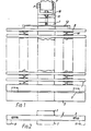
- the vertical spline bar 1 has a transverse support member 2 secured to it by welding or in any other way appropriate to produce a secure electrical contact between them.
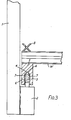
- the support member 2 carries a rectangular contact pin 3 at each end and such pin has inclined contact surfaces 4 ( Figure 3) at its top end.
- the support member 2 co-operates with a transverse spacer 5 which has a corresponding recess 6 to receive the contact pins 3 and has contact surfaces 7 to coact with contact surfaces 4.
- the recesses 6 are demensioned in such a way that a definite air gap exists between the sides of the pin 3 and the sides of the slot 6, within which liquid can rise to some extent under hydrostatic force, and through general expansion/contraction of the entrapped air due to thermal effects in the processing but cannot reach the contact surfaces 4 and 7.
- the existence of the gap between the sides of the pin below the contact surfaces 4 and the sides of the recess allows easy removal and replacement of the spacers 5.
- a layer of workpieces W are arranged on the support member 2 and a transverse spacer bar 8 is arranged on such workpieces. Further layers of workpieces W, separated by spacer bars 8, complete the stack carried by the jig.
- the spline 1 is preferably connected to its associated flight bar F by a removable pin P.
- the spline preferably carries a stirrup 10 near its top end to support a jack screw 11 and clamp member 12 for clamping the assembly of workpieces down onto the support member 2 to ensure good electrical contact between the support member and all the workpieces and transverse spacers.
- the spacer members 8 are preferably X-shaped, as shown, or of similar shape so that they are to some extent resiliently compressible under vertical pressure. It will be understood that these spacers are stripped by chemical or mechanical means (as appropriate) after each electrolytic treatment operation.
- clamping of the workpieces may be effected by means of stepped wedges inserted between a transverse member secured to the vertical spline member or members and the top spacer member 8. This achieves good electrical connection between all the workpieces and the support member 2, carrying the contact pins 3.
- the necessary clamping pressure may be generated by means of a cranked lever, inserted between the transverse member and the top spacer, and maintained by the insertion of stepped wedges.
- a single vertical spline member 1 is shown. This may be supplemented by a second vertical member inserted at the location shown in Figure 2. This is particularly suitable where clamping of workpieces is effected by leverage and insertion of stepped wedges.
- the construction of the invention may also be employed with equal advantage in a jig structure, in which one or more support members are arranged to extend transversely between two or even more vertical current-carrying members arranged at the ends of the jig, for example at the positions indicated in chain lines at 11 in Figure 2 to replace the vertical member or members 1.
- the flight bar can be replaced by another form of overhead support where appropriate.
- longitudinal structural members may be included to extend between the lower ends of the current-carrying members at opposite ends of the jig.
Landscapes
- Chemical & Material Sciences (AREA)
- Engineering & Computer Science (AREA)
- Chemical Kinetics & Catalysis (AREA)
- Electrochemistry (AREA)
- Materials Engineering (AREA)
- Metallurgy (AREA)
- Organic Chemistry (AREA)
- Electrical Discharge Machining, Electrochemical Machining, And Combined Machining (AREA)
- Physical Vapour Deposition (AREA)
- Electroplating Methods And Accessories (AREA)
Claims (6)
Applications Claiming Priority (2)
| Application Number | Priority Date | Filing Date | Title |
|---|---|---|---|
| GB8214436 | 1982-05-18 | ||
| GB8214436 | 1982-05-18 |
Publications (2)
| Publication Number | Publication Date |
|---|---|
| EP0094812A1 EP0094812A1 (fr) | 1983-11-23 |
| EP0094812B1 true EP0094812B1 (fr) | 1986-08-06 |
Family
ID=10530432
Family Applications (1)
| Application Number | Title | Priority Date | Filing Date |
|---|---|---|---|
| EP19830302729 Expired EP0094812B1 (fr) | 1982-05-18 | 1983-05-13 | Dispositifs de fixation destinés à supporter des pièces allongées horizontales dans l'anodisation et dans des procédés semblables |
Country Status (6)
| Country | Link |
|---|---|
| EP (1) | EP0094812B1 (fr) |
| JP (1) | JPS58207399A (fr) |
| AU (1) | AU1463283A (fr) |
| DE (1) | DE3365108D1 (fr) |
| ES (1) | ES522486A0 (fr) |
| NZ (1) | NZ204200A (fr) |
Cited By (2)
| Publication number | Priority date | Publication date | Assignee | Title |
|---|---|---|---|---|
| DE4117799A1 (de) * | 1991-05-30 | 1992-12-03 | Espili Amir Hassani | Rahmenartiges gestell zur aufnahme von zu eloxierenden werkstuecken aus aluminium |
| DE4218182A1 (de) * | 1992-06-02 | 1993-12-09 | Stodal Ind Service Eggelsberg | Vorrichtung zum Aufbringen galvanischer Überzüge |
Families Citing this family (5)
| Publication number | Priority date | Publication date | Assignee | Title |
|---|---|---|---|---|
| FR2792004B1 (fr) * | 1999-04-08 | 2002-02-15 | Electro Rech | Dispositif modulaire pour l'accrochage de pieces devant etre revetues de peinture par electrodeposition |
| GB0016960D0 (en) | 2000-07-12 | 2000-08-30 | Bae Systems Plc | A jig and a method and appratus of applying a surface treatment to a member on the jig |
| ITVR20110079A1 (it) * | 2011-04-22 | 2012-10-23 | Girardini S R L | Appendino per bilancella smontabile. |
| CN104762649A (zh) * | 2015-03-30 | 2015-07-08 | 苏州市新鸿基精密部品有限公司 | 快速更换铝合金阳极氧化挂具 |
| CN110257885A (zh) * | 2019-07-31 | 2019-09-20 | 河池市机务材料有限公司 | 一种松孔镀铬电镀工具 |
Family Cites Families (4)
| Publication number | Priority date | Publication date | Assignee | Title |
|---|---|---|---|---|
| AT363749B (de) * | 1979-03-02 | 1981-08-25 | Kollmorgen Tech Corp | Gestell mit einer klemmvorrichtung zur verwendung in metallisierungsbaedern |
| JPS5689327U (fr) * | 1979-12-13 | 1981-07-17 | ||
| DE3017853A1 (de) * | 1980-05-09 | 1981-11-12 | Günther 7100 Heilbronn Strecker | Galvanisiergestell mit gestellstab und gestellkopf |
| JPS5747123U (fr) * | 1980-08-30 | 1982-03-16 |
-
1983
- 1983-05-11 NZ NZ20420083A patent/NZ204200A/en unknown
- 1983-05-13 DE DE8383302729T patent/DE3365108D1/de not_active Expired
- 1983-05-13 EP EP19830302729 patent/EP0094812B1/fr not_active Expired
- 1983-05-17 ES ES522486A patent/ES522486A0/es active Granted
- 1983-05-17 AU AU14632/83A patent/AU1463283A/en not_active Abandoned
- 1983-05-18 JP JP58087390A patent/JPS58207399A/ja active Pending
Cited By (2)
| Publication number | Priority date | Publication date | Assignee | Title |
|---|---|---|---|---|
| DE4117799A1 (de) * | 1991-05-30 | 1992-12-03 | Espili Amir Hassani | Rahmenartiges gestell zur aufnahme von zu eloxierenden werkstuecken aus aluminium |
| DE4218182A1 (de) * | 1992-06-02 | 1993-12-09 | Stodal Ind Service Eggelsberg | Vorrichtung zum Aufbringen galvanischer Überzüge |
Also Published As
| Publication number | Publication date |
|---|---|
| JPS58207399A (ja) | 1983-12-02 |
| DE3365108D1 (en) | 1986-09-11 |
| ES8404425A1 (es) | 1984-04-16 |
| ES522486A0 (es) | 1984-04-16 |
| AU1463283A (en) | 1983-11-24 |
| NZ204200A (en) | 1985-07-12 |
| EP0094812A1 (fr) | 1983-11-23 |
Similar Documents
| Publication | Publication Date | Title |
|---|---|---|
| CA1082131A (fr) | Electrode pour procede d'electrodeposition | |
| CA1148894A (fr) | Traitement selectif d'un article | |
| US5256262A (en) | System and method for electrolytic deburring | |
| EP0094812A1 (fr) | Dispositifs de fixation destinés à supporter des pièces allongées horizontales dans l'anodisation et dans des procédés semblables | |
| US3090823A (en) | Tank for forming battery elements | |
| US2831808A (en) | Article supporting rack | |
| JP3977421B2 (ja) | 電解洗浄用マザープレート製造方法と該方法により製造されたマザープレート | |
| CN213945824U (zh) | 一种抛光治具及等离子抛光装置 | |
| KR101612715B1 (ko) | 2차 전지 셀 연결용 부스바의 부분도금장치 | |
| GB2089838A (en) | Jigs for electrochemical treatment of elongated workpieces | |
| KR0171642B1 (ko) | 비철금속 전해전착용 음극 | |
| JPS58189397A (ja) | 電解仕上げ処理中材料を支持するキヤリヤ | |
| CA1229817A (fr) | Anodes insolubles pour l'extraction du plomb a partir des electrolytes dans les procedes de recuperation des metaux que renferment les accumulateurs epuises | |
| CN212834073U (zh) | 一种用于蚀刻液再回收的阴极弹出架 | |
| KR102747633B1 (ko) | 태양광패널 프레임용 아노다이징 지그 | |
| JP2023099410A (ja) | 電気めっきラックの固定装置 | |
| JP3283358B2 (ja) | アルミニウムヒートシンク材の陽極酸化処理法 | |
| PL188774B1 (pl) | Uchwyt do płytki wzorcowej | |
| KR20010073546A (ko) | 전해 제련용 음극판 | |
| KR102428851B1 (ko) | 부스바의 전기도금장치 | |
| CN221297102U (zh) | 一种长铝板阳极氧化辅助支架及装置 | |
| CN111088516A (zh) | 电镀浮架及电镀装置 | |
| CN218697938U (zh) | 一种后压紧式挂钩 | |
| EP0138004A3 (fr) | Procédé pour enlever par électrolyse le dépôt de métal de la surface non plaquée d'une bande de métal plaquée sur une seule surface | |
| CN108677232B (zh) | 一种型材表面处理用的上排装置 |
Legal Events
| Date | Code | Title | Description |
|---|---|---|---|
| PUAI | Public reference made under article 153(3) epc to a published international application that has entered the european phase |
Free format text: ORIGINAL CODE: 0009012 |
|
| AK | Designated contracting states |
Designated state(s): BE CH DE FR GB IT LI LU NL |
|
| RAP1 | Party data changed (applicant data changed or rights of an application transferred) |
Owner name: ALCAN INTERNATIONAL LIMITED |
|
| 17P | Request for examination filed |
Effective date: 19840427 |
|
| RAP1 | Party data changed (applicant data changed or rights of an application transferred) |
Owner name: ALCAN INTERNATIONAL LIMITED |
|
| GRAA | (expected) grant |
Free format text: ORIGINAL CODE: 0009210 |
|
| AK | Designated contracting states |
Kind code of ref document: B1 Designated state(s): BE CH DE FR GB IT LI LU NL |
|
| PG25 | Lapsed in a contracting state [announced via postgrant information from national office to epo] |
Ref country code: NL Effective date: 19860806 Ref country code: LI Effective date: 19860806 Ref country code: IT Free format text: LAPSE BECAUSE OF FAILURE TO SUBMIT A TRANSLATION OF THE DESCRIPTION OR TO PAY THE FEE WITHIN THE PRESCRIBED TIME-LIMIT;WARNING: LAPSES OF ITALIAN PATENTS WITH EFFECTIVE DATE BEFORE 2007 MAY HAVE OCCURRED AT ANY TIME BEFORE 2007. THE CORRECT EFFECTIVE DATE MAY BE DIFFERENT FROM THE ONE RECORDED. Effective date: 19860806 Ref country code: CH Effective date: 19860806 Ref country code: BE Effective date: 19860806 |
|
| REF | Corresponds to: |
Ref document number: 3365108 Country of ref document: DE Date of ref document: 19860911 |
|
| ET | Fr: translation filed | ||
| REG | Reference to a national code |
Ref country code: CH Ref legal event code: PL |
|
| NLV1 | Nl: lapsed or annulled due to failure to fulfill the requirements of art. 29p and 29m of the patents act | ||
| PG25 | Lapsed in a contracting state [announced via postgrant information from national office to epo] |
Ref country code: LU Free format text: LAPSE BECAUSE OF NON-PAYMENT OF DUE FEES Effective date: 19870531 |
|
| PLBE | No opposition filed within time limit |
Free format text: ORIGINAL CODE: 0009261 |
|
| STAA | Information on the status of an ep patent application or granted ep patent |
Free format text: STATUS: NO OPPOSITION FILED WITHIN TIME LIMIT |
|
| 26N | No opposition filed | ||
| PG25 | Lapsed in a contracting state [announced via postgrant information from national office to epo] |
Ref country code: DE Effective date: 19890201 |
|
| PGFP | Annual fee paid to national office [announced via postgrant information from national office to epo] |
Ref country code: GB Payment date: 19910426 Year of fee payment: 9 |
|
| PGFP | Annual fee paid to national office [announced via postgrant information from national office to epo] |
Ref country code: FR Payment date: 19910430 Year of fee payment: 9 |
|
| PG25 | Lapsed in a contracting state [announced via postgrant information from national office to epo] |
Ref country code: GB Effective date: 19920513 |
|
| GBPC | Gb: european patent ceased through non-payment of renewal fee |
Effective date: 19920513 |
|
| PG25 | Lapsed in a contracting state [announced via postgrant information from national office to epo] |
Ref country code: FR Effective date: 19930129 |
|
| REG | Reference to a national code |
Ref country code: FR Ref legal event code: ST |