EP0094867B1 - Verfahren und Vorrichtung zur Erfassung und Behandlung geschriebener Daten - Google Patents
Verfahren und Vorrichtung zur Erfassung und Behandlung geschriebener Daten Download PDFInfo
- Publication number
- EP0094867B1 EP0094867B1 EP83400903A EP83400903A EP0094867B1 EP 0094867 B1 EP0094867 B1 EP 0094867B1 EP 83400903 A EP83400903 A EP 83400903A EP 83400903 A EP83400903 A EP 83400903A EP 0094867 B1 EP0094867 B1 EP 0094867B1
- Authority
- EP
- European Patent Office
- Prior art keywords
- trace
- computer
- code
- individual
- detection
- Prior art date
- Legal status (The legal status is an assumption and is not a legal conclusion. Google has not performed a legal analysis and makes no representation as to the accuracy of the status listed.)
- Expired
Links
Images

Classifications
-
- G—PHYSICS
- G06—COMPUTING OR CALCULATING; COUNTING
- G06V—IMAGE OR VIDEO RECOGNITION OR UNDERSTANDING
- G06V10/00—Arrangements for image or video recognition or understanding
- G06V10/10—Image acquisition
- G06V10/17—Image acquisition using hand-held instruments
-
- G—PHYSICS
- G06—COMPUTING OR CALCULATING; COUNTING
- G06V—IMAGE OR VIDEO RECOGNITION OR UNDERSTANDING
- G06V10/00—Arrangements for image or video recognition or understanding
- G06V10/10—Image acquisition
- G06V10/12—Details of acquisition arrangements; Constructional details thereof
Definitions
- US-A-4 241 409 which describes a device providing for deducing a trace by capturing the displacements of mechanical parts and translating these movements into electrical signals (column 4, lines 57 to 59).
- This device also requires the detection of forces and the measurement of angles (column 4 line 59 to column 5 line 2). It is clear that this device leaves practically no freedom to the writer who is forced to conform his writing to a standard writing to which the device compares the plot. This one, moreover, could not be visible since we detect movements and not the concrete result of these movements.
- the problems of contrast, in particular, between the surface receiving the trace and the trace itself are entirely foreign to this invention.
- EP-AO 035 036 which describes a read head using optical character detection means, but these means provide for apprehending all of each drawn character as a finished whole, in the manner of an image or photograph (page 4 lines 15 to 17 and 24 to 26).
- the optical means moreover, take account of the directions in which the various components of the characters are traced and each character is broken down into segments, that is to say into lines having an origin and an arrival, ie two points.
- the device includes a program stored in memory and character recognition supposes the comparison between the stored algorithms and the information collected during the plotting (page 7, lines 5 to 7 and 8 to 25).
- the problem which the invention proposes to solve is therefore different from that to which we have hitherto focused since we do not come up against the difficulty of the global recognition of a sign whose exact morphology and dimensions are different from one writer to another.
- the sign is analyzed optically as it is created, that is to say that one attaches to the course of the tracing instrument more than the overall image finished and constituting a definitive whole.
- the subject of the invention is a method of reading of the direct optical detection type for entering and processing data plotted in clear by a writing instrument known per se on any medium but the appearance of which is contrasted. with respect to the course, characterized in that the significance of the course is determined as long as this course develops by noting certain characteristic points of the course determined by the optical intersection of this course and at least one of several lines of detection and this as many times as an intersection occurs, even if the interested part of the trace has already been in intersection with at least one detection line, that a code known as “individual invariable to each detection line is assigned , that the individual code of a line is recorded each time an optical intersection occurs with it, that a sequence or sequence of individual codes is memorized until its end which is determined by an interruption of the layout for a time greater than a pre-established duration, that a so-called “global” code is assigned to each possible sequence, independently of the order in which the layout is developed, that each of the successive global codes is introduced in a computer of any known type
- the invention also relates to a device for implementing a reading method of the direct optical detection type for entering and processing data plotted in clear on any medium but whose appearance is contrasted with respect to the layout, comprising an optical detection assembly, a transcoder, a calculator, a result delivery member, such as a display dial and a source of electrical energy, characterized on the one hand in that the assembly detection comprises a frame whose so-called “active elements are arranged in radial lines and are connected to the transcoder and, on the other hand, in that an erasable type memory, a timer and a clock are placed at the input of the calculator, in addition and independently of the usual memories specific to this calculator, said detection assembly at least being placed in a pen body carrying a tracing instrument known per se disposed at the virtual center common to the radial lines.
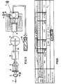
- the device has the general shape of a pen comprising a body 1, one end of which ends with a writing tip 2 of the ball-type while the the other carries two contacts 3 whose usefulness will be specified later.
- the body 1 can receive a cap 4 provided with a clip 5 and which can cooperate with the body 1 either by one end or by the other according to any known means.
- the actual end of the body 1 where the writing tip 2 is located is provided with a lens 6 pierced in its center to provide a passage for the tip 2.
- the cap 4 has a removable end 4a closing off a housing in which a battery 7 of any known type must be placed, the contacts 7a of which are intended to bear on the contacts 3 of the body 1 when the cap 4 having been removed from its position tip protection 2 (fig. 1) was placed on the other end of body 1 (fig. 2).
- the device is then powered and can operate as will be described now.
- a frame 8 In the axis of the lens 6 and in its immediate vicinity, there is a frame 8, the details of which will be given below with reference to FIGS. 3 and 4 and which is electronically connected to a transcoder 9 constituted here by a photo-detector such as a photocell. This is connected electronically to a comparator or analyzer 10 of any type known per se, connected to a clock timer 11 associated with an erasable memory 12.
- This assembly is placed and connected to the input of a computer of any known type comprising a decoder 13 and a memory microprocessor 14, all supplied from the battery 7.
- a small lighting lamp 15 is associated with the lens 6 in order to project a light ray onto the support A on which the user draws by means of the tip 2.
- the frame 8 consists of a solid disc 8a in which are formed very fine slots 8b which radiate from a virtual center which is that of the disc 8a.
- the central part of the disc 8a is occupied by a circular passage 8c intended for the tracing tip 2.
- each slot 8b has been assigned a mark assigned clockwise from A to H and from 1 to 8, so that each diametral slot is designated by the combination of a letter and a number: A-1, C-3, E-5, etc.
- FIG. 4 shows seven phases of the drawing of the figure "8 and, for clarity of the drawing, the frame 8 and the slots 8b are shown diagrammatically by simple lines.
- Phase I corresponds to the starting point, that is to say that no segment of the route is yet visible.
- Phase II represents the beginning of the first loop that the writer traces here from left to right.
- Phase III represents the end of the first loop supposed to extend from the summit to the crossing center.
- Phase IV represents the route of half of the lower loop.
- Phase V represents the continuation of the route just before the crossing point.
- Phase VI represents roughly half the route of the last upper loop.
- Phase VII represents the end of the track and, here, this end is a little above the starting point as the writer wanted.
- Each trace must, however, be recognized in order to be able to be processed in the computer so that we must, first, assign an individual invariable code to each slot, then then constitute standard sequences, or sequences, to each of which affects a global code.
- timer 11 which notes a total interruption in tracing when the tip is lifted from the support A to write the next digit or symbol for a predetermined time.
- sequences are determined not only by the presence of the individual codes but also by the order in which these individual codes appear.
- Each sequence being formed is temporarily stored in memory 12, then is then introduced into decoder 13 of the computer.
- This operation is exactly equivalent to pressing a keyboard key for a conventional calculating machine using a calculator of the same type.
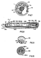
- the body 1 comprises a dial 16 of any known type, and in particular with liquid crystal, on which the result is displayed.
- FIG. 6 constitutes a diagram developing the various operations carried out.
- the memory 12 records the individual codes corresponding to the slots 8b and which correspond to the “geometric code of FIG. 3 and that for the digit“ 0 ”.
- a is at least equal to a predetermined time which is represented in figure 6 by the column x constituting the origin of the arrow F1 signifying that this time interval has the effect of transforming the sequence of individual binary code into a global binary code signifying the digit "0".
- the time interval represented by column x1 is determined by the timer 11 timer and it is therefore at the end of this time interval that the global coding and erasing of the memory 12 ready takes place, thus, to receive the following sequence.
- the order can either be provided by means of a trace such as "C” or "CE” according to international standardization.
- buttons 17 and 18 can also provide on the body 1, two buttons 17 and 18 corresponding to these conventional functions.
- the walls 20 and 21 can, in particular, be made in the form of shells of synthetic material connected by spacers (not shown) to form a whole integral with the components and which can be removed and put in place easily.
- the tracing tip 200 and its cartridge 200a are placed laterally, which allows the entire interior space of the body 100 to be used to house the various electronic components.
- the geometry of the optical detection assembly must be a little different and it can be seen that the axis a of the lens 600 makes with the axis p of the writing tip 200 an angle ⁇ .
- this particular shape of the device makes it possible to symmetrically locate, on either side of the writing tip 200, two lighting members 24 and 25 intended, as we have said with regard to the member 15, to illuminate the plane A on which the user is tracing, in view to increase the contrast between this plane A and the tracing itself.
- the tracing point partly extends over the corresponding screen 800, as can be seen in FIG. 10.
- the invention also allows other uses which consist of any combination of a plot and a calculator.
- Sockets 26 and 27 can be provided to connect the portable device according to the invention to a large computer by means of a light cable (not shown).
- the frame can, as we have said, be constituted by a solid disc notched with slots or, on the contrary, be constituted by an opaque network leaving areas through which the light passes.
- instrument to be traced can be of any known type: ballpoint, pen, felt, etc.
Landscapes
- Engineering & Computer Science (AREA)
- Physics & Mathematics (AREA)
- General Physics & Mathematics (AREA)
- Multimedia (AREA)
- Theoretical Computer Science (AREA)
- Position Input By Displaying (AREA)
- Character Discrimination (AREA)
- Analysing Materials By The Use Of Radiation (AREA)
- Investigating Or Analysing Biological Materials (AREA)
- Calculators And Similar Devices (AREA)
- Image Analysis (AREA)
Claims (7)
Priority Applications (1)
| Application Number | Priority Date | Filing Date | Title |
|---|---|---|---|
| AT83400903T ATE29608T1 (de) | 1982-05-18 | 1983-05-05 | Verfahren und vorrichtung zur erfassung und behandlung geschriebener daten. |
Applications Claiming Priority (2)
| Application Number | Priority Date | Filing Date | Title |
|---|---|---|---|
| FR8208634A FR2527362B1 (fr) | 1982-05-18 | 1982-05-18 | Procede et dispositif pour la saisie et le traitement de donnees tracees en clair |
| FR8208634 | 1982-05-18 |
Publications (2)
| Publication Number | Publication Date |
|---|---|
| EP0094867A1 EP0094867A1 (de) | 1983-11-23 |
| EP0094867B1 true EP0094867B1 (de) | 1987-09-09 |
Family
ID=9274133
Family Applications (1)
| Application Number | Title | Priority Date | Filing Date |
|---|---|---|---|
| EP83400903A Expired EP0094867B1 (de) | 1982-05-18 | 1983-05-05 | Verfahren und Vorrichtung zur Erfassung und Behandlung geschriebener Daten |
Country Status (5)
| Country | Link |
|---|---|
| EP (1) | EP0094867B1 (de) |
| JP (1) | JPS5917675A (de) |
| AT (1) | ATE29608T1 (de) |
| DE (1) | DE3373575D1 (de) |
| FR (1) | FR2527362B1 (de) |
Families Citing this family (11)
| Publication number | Priority date | Publication date | Assignee | Title |
|---|---|---|---|---|
| GB8616470D0 (en) * | 1985-11-05 | 1986-08-13 | Hilton C | Optical scanner |
| GB2208733B (en) * | 1985-11-05 | 1990-11-07 | Nat Res Dev | A writing instrument for use in capturing information in drawing or writing |
| EP0362970A3 (de) * | 1985-11-05 | 1990-08-16 | Btg International Limited | Schreibgerät zur Informationserfassung beim Zeichnen und Schreiben |
| GB8702302D0 (en) * | 1987-02-02 | 1987-03-11 | Parks J R | Capturing information in drawing & writing |
| GB2219119B (en) * | 1989-04-05 | 1993-05-19 | Richard Douglas Haigh | Processing pen |
| JPH03218149A (ja) * | 1990-01-24 | 1991-09-25 | Nec Corp | 携帯無線電話機 |
| JP2726594B2 (ja) * | 1991-04-01 | 1998-03-11 | 八洲電機株式会社 | 記憶ペン |
| JPH07287635A (ja) * | 1994-02-24 | 1995-10-31 | Yashima Denki Co Ltd | 記憶ペン |
| EP0693739A3 (de) * | 1994-07-13 | 1997-06-11 | Yashima Denki Kk | Zur Handschriftspeicherung und -wiedergabe geeignetes Verfahren und Apparat |
| US5748808A (en) * | 1994-07-13 | 1998-05-05 | Yashima Electric Co., Ltd. | Image reproducing method and apparatus capable of storing and reproducing handwriting |
| US7145556B2 (en) | 2001-10-29 | 2006-12-05 | Anoto Ab | Method and device for decoding a position-coding pattern |
Family Cites Families (11)
| Publication number | Priority date | Publication date | Assignee | Title |
|---|---|---|---|---|
| GB1012445A (de) * | 1961-08-25 | |||
| GB1494901A (en) * | 1974-04-30 | 1977-12-14 | Suisse Horlogerie | Data entry and decoding system |
| JPS51110926A (ja) * | 1975-03-26 | 1976-09-30 | Kogyo Gijutsuin | Tegakijohonyuryokuhoshiki |
| US4141073A (en) * | 1977-08-08 | 1979-02-20 | Tan Lu Jan | Keyless electronic calculating pen |
| JPS5926974B2 (ja) * | 1977-12-28 | 1984-07-02 | 富士通株式会社 | オンライン手書き文字入力装置 |
| US4241409A (en) * | 1977-12-30 | 1980-12-23 | Nolf Jean Marie | Hand held pen-size calculator |
| JPS5520575A (en) * | 1978-07-31 | 1980-02-14 | Fujitsu Ltd | Information input pen |
| JPS5533292A (en) * | 1978-08-30 | 1980-03-08 | Fujitsu Ltd | Information input pen |
| JPS5563460A (en) * | 1978-11-04 | 1980-05-13 | Dokou Tan | Keyless computer |
| WO1980002337A1 (fr) * | 1979-04-17 | 1980-10-30 | R Fujita | Dispositif d'entree pour caracteres et motifs manuscrits |
| FR2457523A2 (fr) * | 1979-05-21 | 1980-12-19 | Option Sa | Dispositif d'inscription et de traduction informatique d'un trace par effet capacitif entre la pointe d'un stylo a bille et un reseau de barres conductrices excitees sequentiellement |
-
1982
- 1982-05-18 FR FR8208634A patent/FR2527362B1/fr not_active Expired
-
1983
- 1983-05-05 AT AT83400903T patent/ATE29608T1/de not_active IP Right Cessation
- 1983-05-05 DE DE8383400903T patent/DE3373575D1/de not_active Expired
- 1983-05-05 EP EP83400903A patent/EP0094867B1/de not_active Expired
- 1983-05-18 JP JP58086020A patent/JPS5917675A/ja active Pending
Also Published As
| Publication number | Publication date |
|---|---|
| DE3373575D1 (en) | 1987-10-15 |
| FR2527362A1 (fr) | 1983-11-25 |
| ATE29608T1 (de) | 1987-09-15 |
| FR2527362B1 (fr) | 1987-10-30 |
| JPS5917675A (ja) | 1984-01-28 |
| EP0094867A1 (de) | 1983-11-23 |
Similar Documents
| Publication | Publication Date | Title |
|---|---|---|
| EP0094867B1 (de) | Verfahren und Vorrichtung zur Erfassung und Behandlung geschriebener Daten | |
| EP0211727B1 (de) | Eingabevorrichtung für graphische Daten | |
| EP0589755B1 (de) | Spielterminal | |
| EP0925570B1 (de) | Tragbare leseeinrichtung für blinde | |
| US6573887B1 (en) | Combined writing instrument and digital documentor | |
| US6686910B2 (en) | Combined writing instrument and digital documentor apparatus and method of use | |
| WO1988002586A1 (fr) | Procede et dispositif portatif pour saisir, memoriser et eventuellement traiter et reproduire des signes graphiques figurant sur un support quelconque | |
| US20030195749A1 (en) | Reading machine | |
| CN102855029A (zh) | 输入设备 | |
| JP2009163354A (ja) | 情報記録のための媒体、情報読み取り装置、情報入力システム | |
| FR2988874A1 (fr) | Procede de detection d'un point de contact entre une pointe d'un ustensile et un support d'ecriture | |
| FR2533044A1 (fr) | Procede d'introduction de donnees de modeles graphiques | |
| EP0587484B1 (de) | Vorrichtung zur Analyse von Informationsträgern von Spielscheinen | |
| FR2919937A1 (fr) | Procede de confection et d'envoi automatique d'un message electronique ecrit a la main a un destinataire designe manuellement au moyen de l'instrument d'ecriture et moyens pour sa mise en oeuvre | |
| FR2805359A1 (fr) | Systeme et procede de commande dans un environnement informatique | |
| FR2861886A1 (fr) | Dispositif et procede de traitement d'informations selectionnees dans un tableau hyperdense | |
| FR2807560A1 (fr) | Procede et appareil d'edition d'images representatives d'idees | |
| FR2513780A1 (fr) | Procede pour saisir des extraits de textes d'un modele, et dispositif pour la mise en oeuvre de ce procede | |
| NL9200329A (nl) | Werkwijze en inrichting voor het inlezen van op regel geplaatste beeldinformatie. | |
| FR2632097A1 (fr) | Dispositif d'enregistrement et de lecture d'information organisee en structure hierarchique en arbre | |
| CA1301364C (fr) | Procede et dispositif portatif pour saisir, memoriser et eventuellement traiter et reproduire des signes graphiques figurant sur un support quelconque | |
| WO1990015399A1 (fr) | Dispositif electromecanique de reconnaissance de caracteres executes manuellement | |
| EP3830753B1 (de) | Verfahren zur decodierung eines innenbearbeiteten einsatzes | |
| FR2667825A1 (fr) | Produit grave a gravure codee, notamment document, moyen pour la realisation d'un tel produit et moyen de lecture d'un tel produit. | |
| FR2746525A1 (fr) | Procede et dispositif de saisie manuelle de symboles avec guidage |
Legal Events
| Date | Code | Title | Description |
|---|---|---|---|
| PUAI | Public reference made under article 153(3) epc to a published international application that has entered the european phase |
Free format text: ORIGINAL CODE: 0009012 |
|
| AK | Designated contracting states |
Designated state(s): AT BE CH DE GB IT LI LU NL SE |
|
| 17P | Request for examination filed |
Effective date: 19840409 |
|
| GRAA | (expected) grant |
Free format text: ORIGINAL CODE: 0009210 |
|
| AK | Designated contracting states |
Kind code of ref document: B1 Designated state(s): AT BE CH DE GB IT LI LU NL SE |
|
| REF | Corresponds to: |
Ref document number: 29608 Country of ref document: AT Date of ref document: 19870915 Kind code of ref document: T |
|
| ITF | It: translation for a ep patent filed | ||
| REF | Corresponds to: |
Ref document number: 3373575 Country of ref document: DE Date of ref document: 19871015 |
|
| GBT | Gb: translation of ep patent filed (gb section 77(6)(a)/1977) | ||
| PLBE | No opposition filed within time limit |
Free format text: ORIGINAL CODE: 0009261 |
|
| STAA | Information on the status of an ep patent application or granted ep patent |
Free format text: STATUS: NO OPPOSITION FILED WITHIN TIME LIMIT |
|
| 26N | No opposition filed | ||
| ITTA | It: last paid annual fee | ||
| EPTA | Lu: last paid annual fee | ||
| EAL | Se: european patent in force in sweden |
Ref document number: 83400903.7 |
|
| PGFP | Annual fee paid to national office [announced via postgrant information from national office to epo] |
Ref country code: AT Payment date: 19981127 Year of fee payment: 16 |
|
| PGFP | Annual fee paid to national office [announced via postgrant information from national office to epo] |
Ref country code: NL Payment date: 19981130 Year of fee payment: 16 |
|
| PGFP | Annual fee paid to national office [announced via postgrant information from national office to epo] |
Ref country code: DE Payment date: 19990428 Year of fee payment: 16 |
|
| PG25 | Lapsed in a contracting state [announced via postgrant information from national office to epo] |
Ref country code: AT Free format text: LAPSE BECAUSE OF NON-PAYMENT OF DUE FEES Effective date: 19990505 |
|
| PGFP | Annual fee paid to national office [announced via postgrant information from national office to epo] |
Ref country code: GB Payment date: 19990805 Year of fee payment: 17 |
|
| PGFP | Annual fee paid to national office [announced via postgrant information from national office to epo] |
Ref country code: CH Payment date: 19990818 Year of fee payment: 17 |
|
| PGFP | Annual fee paid to national office [announced via postgrant information from national office to epo] |
Ref country code: LU Payment date: 19991104 Year of fee payment: 17 |
|
| PGFP | Annual fee paid to national office [announced via postgrant information from national office to epo] |
Ref country code: SE Payment date: 19991126 Year of fee payment: 17 |
|
| PG25 | Lapsed in a contracting state [announced via postgrant information from national office to epo] |
Ref country code: NL Free format text: LAPSE BECAUSE OF NON-PAYMENT OF DUE FEES Effective date: 19991201 |
|
| PGFP | Annual fee paid to national office [announced via postgrant information from national office to epo] |
Ref country code: BE Payment date: 19991210 Year of fee payment: 17 |
|
| NLV4 | Nl: lapsed or anulled due to non-payment of the annual fee |
Effective date: 19991201 |
|
| PG25 | Lapsed in a contracting state [announced via postgrant information from national office to epo] |
Ref country code: DE Free format text: LAPSE BECAUSE OF NON-PAYMENT OF DUE FEES Effective date: 20000301 |
|
| PG25 | Lapsed in a contracting state [announced via postgrant information from national office to epo] |
Ref country code: LU Free format text: LAPSE BECAUSE OF NON-PAYMENT OF DUE FEES Effective date: 20000505 Ref country code: GB Free format text: LAPSE BECAUSE OF NON-PAYMENT OF DUE FEES Effective date: 20000505 |
|
| PG25 | Lapsed in a contracting state [announced via postgrant information from national office to epo] |
Ref country code: SE Free format text: LAPSE BECAUSE OF NON-PAYMENT OF DUE FEES Effective date: 20000506 |
|
| PG25 | Lapsed in a contracting state [announced via postgrant information from national office to epo] |
Ref country code: LI Free format text: LAPSE BECAUSE OF NON-PAYMENT OF DUE FEES Effective date: 20000531 Ref country code: CH Free format text: LAPSE BECAUSE OF NON-PAYMENT OF DUE FEES Effective date: 20000531 Ref country code: BE Free format text: LAPSE BECAUSE OF NON-PAYMENT OF DUE FEES Effective date: 20000531 |
|
| BERE | Be: lapsed |
Owner name: SERINA DOMINIQUE Effective date: 20000531 |
|
| GBPC | Gb: european patent ceased through non-payment of renewal fee |
Effective date: 20000505 |
|
| REG | Reference to a national code |
Ref country code: CH Ref legal event code: PL |
|
| EUG | Se: european patent has lapsed |
Ref document number: 83400903.7 |