EP0094871A1 - Elektronisches Relais zur Lichtbogendetektion - Google Patents
Elektronisches Relais zur Lichtbogendetektion Download PDFInfo
- Publication number
- EP0094871A1 EP0094871A1 EP83400934A EP83400934A EP0094871A1 EP 0094871 A1 EP0094871 A1 EP 0094871A1 EP 83400934 A EP83400934 A EP 83400934A EP 83400934 A EP83400934 A EP 83400934A EP 0094871 A1 EP0094871 A1 EP 0094871A1
- Authority
- EP
- European Patent Office
- Prior art keywords
- circuit
- arc
- fault
- voltage
- trigger circuit
- Prior art date
- Legal status (The legal status is an assumption and is not a legal conclusion. Google has not performed a legal analysis and makes no representation as to the accuracy of the status listed.)
- Granted
Links
- 238000001514 detection method Methods 0.000 title description 23
- 230000004224 protection Effects 0.000 claims abstract description 18
- 239000004020 conductor Substances 0.000 claims abstract description 15
- 238000001914 filtration Methods 0.000 claims abstract description 6
- 238000000034 method Methods 0.000 claims abstract description 6
- 230000008569 process Effects 0.000 claims abstract description 6
- 238000007493 shaping process Methods 0.000 claims description 7
- 238000009434 installation Methods 0.000 claims description 6
- 238000011144 upstream manufacturing Methods 0.000 claims description 6
- 230000004075 alteration Effects 0.000 claims description 4
- 230000003068 static effect Effects 0.000 claims description 3
- 230000001934 delay Effects 0.000 claims description 2
- 238000010616 electrical installation Methods 0.000 claims description 2
- 230000005284 excitation Effects 0.000 claims description 2
- 230000008859 change Effects 0.000 abstract description 2
- 230000009466 transformation Effects 0.000 abstract 8
- 238000010586 diagram Methods 0.000 description 5
- 230000001052 transient effect Effects 0.000 description 3
- 239000003990 capacitor Substances 0.000 description 2
- 230000006378 damage Effects 0.000 description 2
- 230000002349 favourable effect Effects 0.000 description 2
- 101100536354 Drosophila melanogaster tant gene Proteins 0.000 description 1
- 240000008042 Zea mays Species 0.000 description 1
- 230000001594 aberrant effect Effects 0.000 description 1
- 230000009471 action Effects 0.000 description 1
- 230000002411 adverse Effects 0.000 description 1
- 239000000470 constituent Substances 0.000 description 1
- 238000009795 derivation Methods 0.000 description 1
- 238000010891 electric arc Methods 0.000 description 1
- 230000008030 elimination Effects 0.000 description 1
- 238000003379 elimination reaction Methods 0.000 description 1
- 238000005516 engineering process Methods 0.000 description 1
- 238000002844 melting Methods 0.000 description 1
- 230000008018 melting Effects 0.000 description 1
- 239000002184 metal Substances 0.000 description 1
- 230000010355 oscillation Effects 0.000 description 1
- 230000003071 parasitic effect Effects 0.000 description 1
- 238000011084 recovery Methods 0.000 description 1
- 230000009467 reduction Effects 0.000 description 1
- 230000000717 retained effect Effects 0.000 description 1
- 230000000630 rising effect Effects 0.000 description 1
- 239000007787 solid Substances 0.000 description 1
- 230000008646 thermal stress Effects 0.000 description 1
Images


Classifications
-
- H—ELECTRICITY
- H02—GENERATION; CONVERSION OR DISTRIBUTION OF ELECTRIC POWER
- H02H—EMERGENCY PROTECTIVE CIRCUIT ARRANGEMENTS
- H02H1/00—Details of emergency protective circuit arrangements
- H02H1/0007—Details of emergency protective circuit arrangements concerning the detecting means
- H02H1/0015—Using arc detectors
Definitions
- the invention relates to a device for protecting an electrical installation against a power arc initiated on a busbar of the installation, said device comprising an arc detecting member capable of sending, in the event of a fault d 'arc, a trip order to a breaking device located upstream of the fault.
- the criterion proposed by the present invention overcomes these drawbacks. It simply consists of a permanent analysis of the voltage between the phases of the power circuit. In the event of an arc fault on this circuit, this voltage takes on a very characteristic appearance, which is perfectly distinguished from what is can meet normally, even on a disturbed network. The role of the detection relay is to make this distinction in the shortest possible time and to send the trip order to the circuit breaker.
- the capture can be single-phase, except in very specific cases in the arrangement of the conductors. In fact, in almost all cases, these conductors are bare bars traveling side by side at distances of a few centimeters. Under these conditions, it is obvious that an arc having arisen between two phases will generalize very quickly and that it can therefore be detected between any of the three conductors.
- the arc detection relay is provided with an electronic circuit comprising means for permanent analysis of the alternating voltage U present between the conductors of the busbar, analog means for discriminating the fault sensitive to the alteration of the shape of the tension during the appearance of an arc and cooperating with processing means which develop the triggering process under predetermined conditions.
- the first criterion used in the relay for arc detection is the form criterion.
- the analog means for discriminating the fault comprises a derivative circuit associated with a filtering circuit and with a threshold circuit delivering an output signal during the appearance of a high time derivative and a significant variation in the amplitude of the voltage "U".
- the second intervention criterion used in the relay is the value of the voltage U.
- the relay includes a device for detecting the value of the voltage U, so as to issue a trip order when the effective value of U is between two limits U1 and U2 of predetermined values.
- the value "U1" can be taken quite low (a few tens of volts for example). Its role is essentially to prevent the intervention of the relay when the system is powered down.
- the value "U2" must be greater than the greatest arc voltage that can occur and less than the minimum possible of the network voltage, which leaves a sufficient window in conventional installations.
- An additional intervention criterion for the relay shows the intensity of the current I flowing in the busbar. This criterion is based on a threshold Is low enough for any fault with an arc to be greater than this threshold, for example of the order of magnitude of the nominal current. The relay will not operate as long as the current is below the Is threshold.
- the three intervention criteria of the relay using the form and value of the voltage and current intensity can be combined by an AND logic function to avoid the risks of inadvertent tripping.
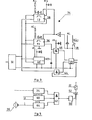
- Fig. 1 schematically shows a cabinet 10 of a Low Voltage distribution panel containing a busbar 12 with conductors L1, L2, L3 supplied by an incoming circuit breaker 14. The latter, placed at the input of the panel, is electrically connected to the supply network or to an MV / LV transformer.
- the cabinet 10 can receive any fixed or withdrawable electrical equipment, and there is shown, by way of example, a three-phase feeder 16 connected to the busbar 12 and protected by an outgoing circuit breaker 18.
- the incoming circuit breaker 14 comprises a conventional thermomagnetic or electronic trip device capable of causing the automatic opening of the contacts of the circuit breaker 14 when the current intensity exceeds a predetermined tripping threshold, for example in the event of an overload or short-term circuit.
- Auxiliary trip means can also be incorporated in the circuit breaker 14, in particular for the detection of a differential fault or a lack of voltage on the network.
- additional protection is assigned to the incoming circuit breaker 14 and includes an arc detection relay designated by the general reference 20.
- This relay 20 is used to detect, inside the cabinet 10, the presence of an arc on the busbar 12 and to send, after processing, an instantaneous tripping order to a coil 22 for controlling the opening of the incoming circuit breaker 14.
- a supply circuit AL is associated with the arc detection relay 20 and with the trip coil circuit 22.
- a first input of the relay 20 is connected by connecting conductors 24 to the various network phases upstream of the circuit breaker 14 of arrival.
- a second input of the relay 20 is electrically connected to current sensors 26 capable of delivering the image of the current flowing in the busbar 12 in the closed position of the circuit breaker 14.
- the arc 20 is detected by the relay by permanent analysis of the voltage U, for example, between the phase conductors of the network upstream of the circuit breaker 14.
- This voltage U is identical to that existing between the conductors L1, L2, L3 of the busbar 12.
- the presence of an arc on the busbar 12 results in an alteration of the shape of the voltage U compared to its shape under normal operating conditions.
- the role of relay 20 consists in making this distinction in the shortest possible time and sending the trip order to the incoming circuit breaker 14.
- the first disturbance detection function is provided by an analog part of the relay 20 which includes a filter circuit 28 with active bandpass filter associated with a threshold circuit 30, sensitive to the amplitude of the variation of the voltage U.
- the arc voltage wave is in fact characterized by a rising edge, the very high dU of which is detected by the derivation of the voltage signal U.
- the filtering circuit 28 keeps only a range of frequencies in which these steep edges are located:
- the low cut-off frequency of the bandpass filter is of the order of 300 Hz, so as to reject the fundamental frequency 50 Hz and its harmonics up to the order of 5.
- the high cutoff frequency is in the vicinity of 8 kHz to eliminate high frequencies having no correlation with an arc fault.
- the threshold circuit 30 makes it possible to eliminate certain parasitic phenomena which may exist in normal operation and to retain exclusively the stiff edges generating an abrupt variation in voltage of a predetermined amplitude.
- the threshold circuit 30 is composed of a positive threshold and a negative threshold of identical values, so as to take account of the positive and negative variations of the arc voltage.
- the threshold circuit 30 delivers an output signal which can have two logic states 0 or 1 indicating either the presence or the absence of an arc on the busbar. Several pulses close in time (less than 1 ms) are considered as a single pulse thanks to a diode and capacitor circuit associated with the output ⁇ of the threshold circuit 30.
- the second function for distinguishing between a passing incident and an actual arc fault is operated by the digital part of the relay 20 located after the threshold circuit 30.
- the pulse delivered by the threshold circuit 30 corresponds well to an arc fault on the busbar 12 and not to passenger incidents due, for example, to the opening of a circuit breaker located downstream, to the transient absence voltage, to transient voltage recovery phenomena giving rise to voltage oscillations or to the supply of the Low Voltage network by closing a circuit breaker whose contacts bounce.
- the output of the threshold circuit 30 is connected to a shaping circuit 32 connected to a logic processing circuit 34 which will be described in detail below, with reference to FIG. 3.
- the logic processing circuit 34 (FIG. 3) with sequential binary operators comprises, for example, two monostable flip-flops 36, 38 and two bistable flip-flops 40, 42 of the RS type, supplied by the supply circuit AL.
- the inputs of flip-flops 36, 38, 40 are connected to the output of the shaping circuit 32, and the output of the second flip-flop 42 has a logic level 1 or 0 which indicates the presence or absence of a fault arc.
- One of the inputs of the flip-flop 42 is connected to the shaping circuit 32 via a logic gate 44.
- the other input of the flip-flop 42 is connected to the output of an AND logic gate 46 whose the inputs are connected to the outputs of flip-flops 36 and 40.
- a reset circuit RESET with manual control button 48 is associated with flip-flop 42.
- a fleeting hole or absence of tension can also cause two pulses with stiff edges, one when the tension disappears and another, when it returns.
- the logic processing circuit 34 is arranged so that the tripping order is only issued after a count of three pulses.
- the third pulse of circuit 32 to be taken into account and trigger the relay 20, must occur, for example, at time t3 after the end of time delay T1 of the first monostable flip-flop 36 and necessarily during time delay T2 of the second monostable flip-flop 38.
- the first bistable flip-flop 40 is in state 1 and the AND logic gate 46 is unlocked. The fault is then stored in the second flip-flop 42 which goes from logic state 0 to 1.
- the third function for storing the fault and tripping the incoming circuit breaker 14 is controlled by the output flip-flop 42 of the logic processing circuit 34.
- Changing the logic state 0 to 1 of the second flip-flop 42 generates a pulse trigger applied to a pulse generator 50 connected to the unlocking trigger of a static switch 52, in particular a triac, in series with the trigger coil 22.
- the conduction of the triac ensures the excitation of the coil 22 followed by the opening of the contacts of the incoming circuit breaker 14.
- the presence of the arc fault is simultaneously signaled remotely by means of a display member 54 connected to the latch 42 of the circuit 34 by means of a control device 56.
- the detection of the arc fault by the circuit of FIG. 2 is based on the alteration of the shape of the arc voltage wave, thanks to the permanent analysis of the voltage U between power conductors, thus constituting a first intervention criterion for relay 20.
- the logic circuit 34 must count three pulses before ordering the trip.
- the value "U1" can be taken quite low (a few tens of Volts for example). Its role is essentially to prevent the intervention of the relay when the system is powered down.
- the value "U2" must be greater than the greatest arc voltage that can occur and less than the minimum possible of the network voltage, which leaves a sufficient window in conventional installations.
- This detection mode can be associated with a time delay during which the voltage must remain within the required range. This delay must be sufficient to eliminate voltage fluctuations of very short duration (cut by a downstream device for example).
- This second criterion is developed in a detector device 60 (FIG. 5).
- the two intervention criteria of relay 20 based on the form and the effective value of the voltage "U" can be combined by means of an AND logic gate 62 (FIG. 5). Both criteria must be satisfied simultaneously for the trigger order to be sent to coil 22 of the relay 20.
- This reliability can be further improved by adding a third criterion, in this case the current.
- This criterion is based on a fairly low threshold Is, such that the arc current must be greater than this threshold.
- the current criterion is developed in a comparator 64 (Fig. 5) whose input is connected to the current sensors 26 and whose output is connected to the third input of the AND logic gate 62. The action of the comparator 64 doesn’t intervenes only if the current 1 flowing in the busbar 12 is greater than the threshold Is.
- the arc detection relay 20 according to FIGS. 1 to 5 can be presented as an independent component which can be installed in the switchboard to be protected and conventionally connected, on the one hand to the busbar 12 and, on the other hand, to the circuit breaker 14 to be operated (more , if necessary, to the auxiliary source if it exists and to a current sensor 26, if this criterion is used).
- This embodiment therefore assumes wired links which must be minimized by placing the relay 20 as close as possible to the circuit breaker 14, while ensuring that it is not exposed to a possible arc.
- This last type of embodiment allows, in particular, very easy taking into account of the current criterion, this information being always present at the level of the trip device of the circuit breaker 14.
Landscapes
- Emergency Protection Circuit Devices (AREA)
- Breakers (AREA)
Applications Claiming Priority (2)
| Application Number | Priority Date | Filing Date | Title |
|---|---|---|---|
| FR8208926 | 1982-05-19 | ||
| FR8208926A FR2527381A1 (fr) | 1982-05-19 | 1982-05-19 | Relais electronique de detection d'arc |
Publications (2)
| Publication Number | Publication Date |
|---|---|
| EP0094871A1 true EP0094871A1 (de) | 1983-11-23 |
| EP0094871B1 EP0094871B1 (de) | 1985-12-18 |
Family
ID=9274251
Family Applications (1)
| Application Number | Title | Priority Date | Filing Date |
|---|---|---|---|
| EP83400934A Expired EP0094871B1 (de) | 1982-05-19 | 1983-05-09 | Elektronisches Relais zur Lichtbogendetektion |
Country Status (7)
| Country | Link |
|---|---|
| EP (1) | EP0094871B1 (de) |
| AU (1) | AU555322B2 (de) |
| CA (1) | CA1210847A (de) |
| DE (1) | DE3361547D1 (de) |
| ES (1) | ES8402980A1 (de) |
| FR (1) | FR2527381A1 (de) |
| ZA (1) | ZA833351B (de) |
Cited By (15)
| Publication number | Priority date | Publication date | Assignee | Title |
|---|---|---|---|---|
| EP0196234A3 (en) * | 1985-03-26 | 1988-07-27 | Mitsubishi Denki Kabushiki Kaisha | Gas insulated switchgear |
| EP0508638A3 (en) * | 1991-03-28 | 1993-04-07 | Eaton Corporation | Field sensing arc detection |
| EP0615327A3 (en) * | 1993-02-26 | 1994-09-21 | Westinghouse Electric Corp | Circuit breaker responsive to repeated in-rush currents produced by a sputtering arc fault. |
| US5825598A (en) * | 1997-02-11 | 1998-10-20 | Square D Company | Arcing fault detection system installed in a panelboard |
| US6377427B1 (en) | 1995-03-13 | 2002-04-23 | Square D Company | Arc fault protected electrical receptacle |
| US6452767B1 (en) | 1995-03-13 | 2002-09-17 | Square D Company | Arcing fault detection system for a secondary line of a current transformer |
| US6477021B1 (en) | 1998-02-19 | 2002-11-05 | Square D Company | Blocking/inhibiting operation in an arc fault detection system |
| US6567250B1 (en) | 1998-02-19 | 2003-05-20 | Square D Company | Arc fault protected device |
| US6621669B1 (en) | 1998-02-19 | 2003-09-16 | Square D Company | Arc fault receptacle with a feed-through connection |
| US6782329B2 (en) | 1998-02-19 | 2004-08-24 | Square D Company | Detection of arcing faults using bifurcated wiring system |
| US7068480B2 (en) | 2001-10-17 | 2006-06-27 | Square D Company | Arc detection using load recognition, harmonic content and broadband noise |
| US7136265B2 (en) | 2001-10-17 | 2006-11-14 | Square D Company | Load recognition and series arc detection using bandpass filter signatures |
| US7151656B2 (en) | 2001-10-17 | 2006-12-19 | Square D Company | Arc fault circuit interrupter system |
| US7253637B2 (en) | 2005-09-13 | 2007-08-07 | Square D Company | Arc fault circuit interrupter system |
| CN111192793A (zh) * | 2020-02-27 | 2020-05-22 | 威胜电气有限公司 | 弹操机构防跳跃装置、防跳跃方法、弹操机构和断路器 |
Families Citing this family (12)
| Publication number | Priority date | Publication date | Assignee | Title |
|---|---|---|---|---|
| US5452223A (en) * | 1993-08-20 | 1995-09-19 | Eaton Corporation | Arc detection using current variation |
| US6532424B1 (en) | 1995-03-13 | 2003-03-11 | Square D Company | Electrical fault detection circuit with dual-mode power supply |
| US6242993B1 (en) | 1995-03-13 | 2001-06-05 | Square D Company | Apparatus for use in arcing fault detection systems |
| US5691869A (en) * | 1995-06-06 | 1997-11-25 | Eaton Corporation | Low cost apparatus for detecting arcing faults and circuit breaker incorporating same |
| US5726577A (en) * | 1996-04-17 | 1998-03-10 | Eaton Corporation | Apparatus for detecting and responding to series arcs in AC electrical systems |
| US5818237A (en) * | 1996-06-10 | 1998-10-06 | Eaton Corporation | Apparatus for envelope detection of low current arcs |
| US5847913A (en) | 1997-02-21 | 1998-12-08 | Square D Company | Trip indicators for circuit protection devices |
| US6625550B1 (en) | 1998-02-19 | 2003-09-23 | Square D Company | Arc fault detection for aircraft |
| CN109478774A (zh) * | 2016-05-31 | 2019-03-15 | 西门子股份公司 | 故障电弧识别单元 |
| WO2017207029A1 (de) | 2016-05-31 | 2017-12-07 | Siemens Aktiengesellschaft | Störlichtbogenerkennungseinheit |
| WO2017207031A1 (de) | 2016-05-31 | 2017-12-07 | Siemens Aktiengesellschaft | Störlichtbogenerkennungseinheit |
| CN109496379B (zh) | 2016-05-31 | 2020-04-10 | 西门子股份公司 | 故障电弧识别单元 |
Citations (5)
| Publication number | Priority date | Publication date | Assignee | Title |
|---|---|---|---|---|
| FR799271A (fr) * | 1935-12-13 | 1936-06-10 | Appareil destiné à déceler la présence d'irrégularités anormales d'un courant électrique | |
| DE1126011B (de) * | 1961-02-03 | 1962-03-22 | Siemens Ag | Vorrichtung zur Erfassung und Ortung von Fehlerlichtboegen in elektrischen Anlagen |
| CH369815A (de) * | 1957-09-26 | 1963-06-15 | Siemens Ag | Anordnung zur Vermeidung unzulässig hoher Kurzschlusslichtbogenenergie in elektrischen Anlagen |
| US3588611A (en) * | 1969-10-31 | 1971-06-28 | Westinghouse Electric Corp | Transmission line arc detection and location system |
| DE2103472A1 (de) * | 1971-01-18 | 1972-08-03 | Siemens Ag | Schaltungsanordnung zur Erfassung von elektrischen Wechselstromlichtbogen, |
Family Cites Families (1)
| Publication number | Priority date | Publication date | Assignee | Title |
|---|---|---|---|---|
| DE3169843D1 (en) * | 1980-12-01 | 1985-05-15 | Starkstrom Anlagenbau Veb K | Method and circuit for detecting and breaking disturbing electric arcs |
-
1982
- 1982-05-19 FR FR8208926A patent/FR2527381A1/fr active Granted
-
1983
- 1983-05-09 DE DE8383400934T patent/DE3361547D1/de not_active Expired
- 1983-05-09 EP EP83400934A patent/EP0094871B1/de not_active Expired
- 1983-05-10 ZA ZA833351A patent/ZA833351B/xx unknown
- 1983-05-12 CA CA000427977A patent/CA1210847A/en not_active Expired
- 1983-05-14 ES ES522405A patent/ES8402980A1/es not_active Expired
- 1983-05-19 AU AU14859/83A patent/AU555322B2/en not_active Ceased
Patent Citations (5)
| Publication number | Priority date | Publication date | Assignee | Title |
|---|---|---|---|---|
| FR799271A (fr) * | 1935-12-13 | 1936-06-10 | Appareil destiné à déceler la présence d'irrégularités anormales d'un courant électrique | |
| CH369815A (de) * | 1957-09-26 | 1963-06-15 | Siemens Ag | Anordnung zur Vermeidung unzulässig hoher Kurzschlusslichtbogenenergie in elektrischen Anlagen |
| DE1126011B (de) * | 1961-02-03 | 1962-03-22 | Siemens Ag | Vorrichtung zur Erfassung und Ortung von Fehlerlichtboegen in elektrischen Anlagen |
| US3588611A (en) * | 1969-10-31 | 1971-06-28 | Westinghouse Electric Corp | Transmission line arc detection and location system |
| DE2103472A1 (de) * | 1971-01-18 | 1972-08-03 | Siemens Ag | Schaltungsanordnung zur Erfassung von elektrischen Wechselstromlichtbogen, |
Cited By (16)
| Publication number | Priority date | Publication date | Assignee | Title |
|---|---|---|---|---|
| EP0196234A3 (en) * | 1985-03-26 | 1988-07-27 | Mitsubishi Denki Kabushiki Kaisha | Gas insulated switchgear |
| US4835648A (en) * | 1985-03-26 | 1989-05-30 | Mitsubishi Denki Kabushiki Kaisha | Gas insulated switchgear |
| EP0508638A3 (en) * | 1991-03-28 | 1993-04-07 | Eaton Corporation | Field sensing arc detection |
| EP0615327A3 (en) * | 1993-02-26 | 1994-09-21 | Westinghouse Electric Corp | Circuit breaker responsive to repeated in-rush currents produced by a sputtering arc fault. |
| US6377427B1 (en) | 1995-03-13 | 2002-04-23 | Square D Company | Arc fault protected electrical receptacle |
| US6452767B1 (en) | 1995-03-13 | 2002-09-17 | Square D Company | Arcing fault detection system for a secondary line of a current transformer |
| US5825598A (en) * | 1997-02-11 | 1998-10-20 | Square D Company | Arcing fault detection system installed in a panelboard |
| US6567250B1 (en) | 1998-02-19 | 2003-05-20 | Square D Company | Arc fault protected device |
| US6477021B1 (en) | 1998-02-19 | 2002-11-05 | Square D Company | Blocking/inhibiting operation in an arc fault detection system |
| US6621669B1 (en) | 1998-02-19 | 2003-09-16 | Square D Company | Arc fault receptacle with a feed-through connection |
| US6782329B2 (en) | 1998-02-19 | 2004-08-24 | Square D Company | Detection of arcing faults using bifurcated wiring system |
| US7068480B2 (en) | 2001-10-17 | 2006-06-27 | Square D Company | Arc detection using load recognition, harmonic content and broadband noise |
| US7136265B2 (en) | 2001-10-17 | 2006-11-14 | Square D Company | Load recognition and series arc detection using bandpass filter signatures |
| US7151656B2 (en) | 2001-10-17 | 2006-12-19 | Square D Company | Arc fault circuit interrupter system |
| US7253637B2 (en) | 2005-09-13 | 2007-08-07 | Square D Company | Arc fault circuit interrupter system |
| CN111192793A (zh) * | 2020-02-27 | 2020-05-22 | 威胜电气有限公司 | 弹操机构防跳跃装置、防跳跃方法、弹操机构和断路器 |
Also Published As
| Publication number | Publication date |
|---|---|
| EP0094871B1 (de) | 1985-12-18 |
| ES522405A0 (es) | 1984-03-01 |
| ZA833351B (en) | 1984-02-29 |
| AU555322B2 (en) | 1986-09-18 |
| FR2527381B1 (de) | 1985-04-12 |
| DE3361547D1 (en) | 1986-01-30 |
| ES8402980A1 (es) | 1984-03-01 |
| CA1210847A (en) | 1986-09-02 |
| AU1485983A (en) | 1983-11-24 |
| FR2527381A1 (fr) | 1983-11-25 |
Similar Documents
| Publication | Publication Date | Title |
|---|---|---|
| EP0094871B1 (de) | Elektronisches Relais zur Lichtbogendetektion | |
| EP0313422B1 (de) | Statischer Auslöser für einen Schalter in einem gegossenen Gehäuse | |
| EP0244284B1 (de) | Statischer Momentanauslöser für einen begrenzenden Leistungsschalter | |
| EP0128084B1 (de) | Selektiver elektronischer Auslöser angewendet in einem strombegrenzenden Schalter | |
| EP0537084B1 (de) | Schutzschalter mit selektiver Verriegelung | |
| EP0149372A1 (de) | Fehlerstrom-Differentialeinrichtung ausgestattet mit einer Einrichtung zur Überwachung der Speisung der Elektronik | |
| EP3502721B1 (de) | Testverfahren des differentialschutzes, differentialschutzvorrichtung und elektrisches gerät, das eine solche vorrichtung umfasst | |
| EP0275857A1 (de) | Durch Halbleitern unterstützter ultra-schneller Schalter | |
| EP3577672B1 (de) | Hochspannungsgleichstromunterbrechungsvorrichtung | |
| FR2584529A1 (fr) | Disjoncteur-contacteur electrique, notamment pour des batteries de condensateurs | |
| FR3074914A1 (fr) | Procede de detection de l'etat d'un appareil de protection electrique dans une installation electrique et dispositif de detection mettant en oeuvre ledit procede | |
| EP2267465B1 (de) | Vorrichtung und Verfahren zur Anzeige von elektrischen Fehlern, Einheit und elektrische Schalttafel, die diese Vorrichtung umfassen | |
| BE1005336A0 (fr) | Telerupteur a dispositif de limitation de courant. | |
| FR2545999A1 (fr) | Dispositif de protection contre les surtensions pour une installation ou un reseau electrique a basse tension | |
| FR2497013A1 (fr) | Dispositif de delestage d'une installation electrique basse tension | |
| FR2470466A1 (fr) | Dispositif de protection contre les surtensions | |
| EP0504125B1 (de) | Feuerschutzschalter für Wechsel- und Gleichstrom durch Detektion der Punktkontaktströme | |
| WO2016131867A1 (fr) | Systeme de protection selective d'un reseau electrique et procede de protection associe | |
| EP2693585B1 (de) | Schutzsystem für eine Vielzahl von elektrischen Ableitungen gegen Kurzschlüsse, und Elektroanlage, die ein solches Schutzsystem umfasst | |
| EP0851554B1 (de) | Schutzschalter mit Vorrichtung zum Steueren des Öffnens und elektrische Verteilervorrichtung mit solchem Schalter | |
| FR3104314A1 (fr) | Ensemble d’appareils de protection electriques a deux niveaux connectes en serie. | |
| FR2750266A1 (fr) | Dispositif de protection differentielle | |
| EP0105786B1 (de) | Abzweigschalter mit einem elektronischen Auslöser und einer ferngesteuerten Einstellung | |
| EP1912303B1 (de) | Vorrichtung, die das Eingreifen an einem Abschaltelement ermöglicht, das an eine Restfehlerstrom-Schutzvorrichtung gekoppelt ist, die die Kontinuität der Stromversorgung einer nachgelagerten Ladung sicherstellt | |
| FR2832258A1 (fr) | Procede de securisation d'un systeme de protection differentielle de jeu de barres dans une ligne a isolation gazeuse, et systeme de protection de secours mettant en oeuvre le procede |
Legal Events
| Date | Code | Title | Description |
|---|---|---|---|
| PUAI | Public reference made under article 153(3) epc to a published international application that has entered the european phase |
Free format text: ORIGINAL CODE: 0009012 |
|
| AK | Designated contracting states |
Designated state(s): BE CH DE GB IT LI NL SE |
|
| 17P | Request for examination filed |
Effective date: 19831216 |
|
| ITF | It: translation for a ep patent filed | ||
| GRAA | (expected) grant |
Free format text: ORIGINAL CODE: 0009210 |
|
| AK | Designated contracting states |
Designated state(s): BE CH DE GB IT LI NL SE |
|
| REF | Corresponds to: |
Ref document number: 3361547 Country of ref document: DE Date of ref document: 19860130 |
|
| PLBI | Opposition filed |
Free format text: ORIGINAL CODE: 0009260 |
|
| 26 | Opposition filed |
Opponent name: AEG AKTIENGESELLSCHAFT, BERLIN UND FRANKFURT Effective date: 19860916 |
|
| NLR1 | Nl: opposition has been filed with the epo |
Opponent name: AEG AKTIENGESELLSCHAFT |
|
| PLBN | Opposition rejected |
Free format text: ORIGINAL CODE: 0009273 |
|
| STAA | Information on the status of an ep patent application or granted ep patent |
Free format text: STATUS: OPPOSITION REJECTED |
|
| 27O | Opposition rejected |
Effective date: 19880117 |
|
| NLR2 | Nl: decision of opposition | ||
| PGFP | Annual fee paid to national office [announced via postgrant information from national office to epo] |
Ref country code: SE Payment date: 19890517 Year of fee payment: 7 |
|
| PGFP | Annual fee paid to national office [announced via postgrant information from national office to epo] |
Ref country code: BE Payment date: 19890522 Year of fee payment: 7 |
|
| PGFP | Annual fee paid to national office [announced via postgrant information from national office to epo] |
Ref country code: CH Payment date: 19890523 Year of fee payment: 7 |
|
| ITTA | It: last paid annual fee | ||
| PGFP | Annual fee paid to national office [announced via postgrant information from national office to epo] |
Ref country code: NL Payment date: 19890531 Year of fee payment: 7 Ref country code: GB Payment date: 19890531 Year of fee payment: 7 |
|
| PGFP | Annual fee paid to national office [announced via postgrant information from national office to epo] |
Ref country code: DE Payment date: 19890630 Year of fee payment: 7 |
|
| PG25 | Lapsed in a contracting state [announced via postgrant information from national office to epo] |
Ref country code: GB Effective date: 19900509 |
|
| PG25 | Lapsed in a contracting state [announced via postgrant information from national office to epo] |
Ref country code: SE Effective date: 19900510 |
|
| PG25 | Lapsed in a contracting state [announced via postgrant information from national office to epo] |
Ref country code: LI Effective date: 19900531 Ref country code: CH Effective date: 19900531 Ref country code: BE Effective date: 19900531 |
|
| BERE | Be: lapsed |
Owner name: MERLIN GERIN Effective date: 19900531 |
|
| PG25 | Lapsed in a contracting state [announced via postgrant information from national office to epo] |
Ref country code: NL Effective date: 19901201 |
|
| GBPC | Gb: european patent ceased through non-payment of renewal fee | ||
| NLV4 | Nl: lapsed or anulled due to non-payment of the annual fee | ||
| REG | Reference to a national code |
Ref country code: CH Ref legal event code: PL |
|
| PG25 | Lapsed in a contracting state [announced via postgrant information from national office to epo] |
Ref country code: DE Effective date: 19910201 |
|
| EUG | Se: european patent has lapsed |
Ref document number: 83400934.2 Effective date: 19910115 |