EP0094894B1 - Bauaufzug - Google Patents
Bauaufzug Download PDFInfo
- Publication number
- EP0094894B1 EP0094894B1 EP83420080A EP83420080A EP0094894B1 EP 0094894 B1 EP0094894 B1 EP 0094894B1 EP 83420080 A EP83420080 A EP 83420080A EP 83420080 A EP83420080 A EP 83420080A EP 0094894 B1 EP0094894 B1 EP 0094894B1
- Authority
- EP
- European Patent Office
- Prior art keywords
- mast
- sheet metal
- panels
- elevator
- assembly
- Prior art date
- Legal status (The legal status is an assumption and is not a legal conclusion. Google has not performed a legal analysis and makes no representation as to the accuracy of the status listed.)
- Expired
Links
- 238000010276 construction Methods 0.000 title abstract description 5
- 239000002184 metal Substances 0.000 claims description 31
- 230000000295 complement effect Effects 0.000 claims description 5
- 230000014759 maintenance of location Effects 0.000 claims description 2
- 238000005452 bending Methods 0.000 claims 2
- 238000006073 displacement reaction Methods 0.000 claims 1
- 230000002787 reinforcement Effects 0.000 claims 1
- 229910000831 Steel Inorganic materials 0.000 abstract 1
- 239000010959 steel Substances 0.000 abstract 1
- 230000000694 effects Effects 0.000 description 2
- 238000004519 manufacturing process Methods 0.000 description 2
- 238000000034 method Methods 0.000 description 2
- 125000006850 spacer group Chemical group 0.000 description 2
- 238000003860 storage Methods 0.000 description 2
- 241000282341 Mustela putorius furo Species 0.000 description 1
- 239000000470 constituent Substances 0.000 description 1
- 238000009826 distribution Methods 0.000 description 1
- 230000003313 weakening effect Effects 0.000 description 1
- 238000003466 welding Methods 0.000 description 1
Images


Classifications
-
- B—PERFORMING OPERATIONS; TRANSPORTING
- B66—HOISTING; LIFTING; HAULING
- B66B—ELEVATORS; ESCALATORS OR MOVING WALKWAYS
- B66B9/00—Kinds or types of lifts in, or associated with, buildings or other structures
- B66B9/16—Mobile or transportable lifts specially adapted to be shifted from one part of a building or other structure to another part or to another building or structure
- B66B9/187—Mobile or transportable lifts specially adapted to be shifted from one part of a building or other structure to another part or to another building or structure with a liftway specially adapted for temporary connection to a building or other structure
-
- Y—GENERAL TAGGING OF NEW TECHNOLOGICAL DEVELOPMENTS; GENERAL TAGGING OF CROSS-SECTIONAL TECHNOLOGIES SPANNING OVER SEVERAL SECTIONS OF THE IPC; TECHNICAL SUBJECTS COVERED BY FORMER USPC CROSS-REFERENCE ART COLLECTIONS [XRACs] AND DIGESTS
- Y10—TECHNICAL SUBJECTS COVERED BY FORMER USPC
- Y10S—TECHNICAL SUBJECTS COVERED BY FORMER USPC CROSS-REFERENCE ART COLLECTIONS [XRACs] AND DIGESTS
- Y10S187/00—Elevator, industrial lift truck, or stationary lift for vehicle
- Y10S187/90—Temporary construction elevator for building
Definitions
- the present invention relates to a rack or cable site lift, that is to say a lift or elevator, of the type comprising a mast of polygonal section, generally rectangular or square, composed of assemblable elements and intended to be moored against the exterior face of a construction as it rises and two angles of the same face of which constitute the raceways of a cabin in which personnel and / or equipment can take place, means such as that rack or cable being provided to allow the cabin to be moved along the aforementioned face of the mast and to be stopped at any desired level.
- a rack or cable site lift that is to say a lift or elevator, of the type comprising a mast of polygonal section, generally rectangular or square, composed of assemblable elements and intended to be moored against the exterior face of a construction as it rises and two angles of the same face of which constitute the raceways of a cabin in which personnel and / or equipment can take place, means such as that rack or cable being provided to allow the cabin to be moved along the aforementioned face of the mast and to
- each element of the mast forms a one-piece assembly consisting of tubular parts assembled by welding and of which at least two angles are constituted by tubes of square section or rectangular, free on at least three of their faces, each of which receives at least one support or guide roller, carried by the cabin.
- each element ends in a cross section perpendicular to its longitudinal axis and that, consequently, all the joints between successive elements are contained in planes orthogonal to this longitudinal axis, which does not contribute to a good flexural strength of the mast.
- the assembly of the sheet metal panels is of the removable type and each panel corresponds substantially to a section of one of the lateral faces of the mast and whose longitudinal edges are folded and pierced with rows of holes for rapid assembly and disassembly at sheet metal panels of the adjacent faces, the panels of the same face of the mast being offset longitudinally with respect to the panels of the other faces of this mast, so that each joint between two panels of one face is at a level different from the joints of the panels on the other sides.
- this mast by sheets, each of which corresponds only to one of its faces allows, by a judicious offset of the sheets of two adjacent faces, to offset their respective joint planes and, consequently, avoid the mast having transverse joint planes weakening its stiffness.
- each sheet metal panel constituting a section of one of the faces of the mast has longitudinal edges bent at 90 ° and the raceways for the rollers of the cabin are constituted by folded sheet metal profiles having two longitudinal assembly wings folded at 90 ° relative to each other and rows of holes having the same distribution as those of the sheet metal panels of the lateral faces of the mast, so as to allow their assembly using the same bolts.
- the sheet metal panels of the four faces of the mast are identical, which facilitates the storage and mounting of these panels.
- the raceways for the rollers of the cabin consist of longitudinal ribs obtained by bends and counter-bends made between the central core and the assembly wings folded 90 ° sheet metal panels corresponding to the face of the mast along which the cabin moves.
- the sheet metal panels making up the mast have transverse ribs allowing their stiffening and bosses allowing the fixing of a rack.
- each sheet metal panel has an angled-shaped stamp allowing it to be clamped simultaneously with the corresponding edges of the adjacent panel, using flanges having a profile complementary to that of the two stampings placed at the end. at the end.
- the bolt through holes in the sheet metal panels as well as in the wings of the profiles possibly forming raceways are formed in frustoconical bowls capable of fitting together 'one in the other.
- recesses are provided which can occupy each part of the panel in non-ribbed sheet metal.
- the presence of these recesses has in Q utre, the advantage of reducing the wind resistance.
- each raceway a single track of trapezoidal cross section intended to receive rollers of complementary section capable of ensuring, simultaneously, the support, the retention and the guiding of the cabin.
- this site lift is of the type comprising a mast (2) of square section moored against the outside face (3a) of a building (3) under construction as the ferret rises of this building.
- Two angles (4) and (5) of the mast (2) adjacent to the same lateral face of this mast are arranged to present raceways for the rollers not visible in FIG. 1, of a cabin (6) intended to be moved along the aforementioned face of the mast (2) and along the face (3a) of the building (3).
- the driving of the cabin (6) along the mast (2) is ensured by the engagement of a driving pinion (7) carried by the cabin (6), in a rack (8) carried by the aforementioned face of the mast (2).
- a bracket (9) carried by the roof of the cabin (6) makes it possible to increase the height of the mast (2) as and when required during the construction of the building (3).
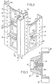
- the mast (2) of this elevator consists of the assembly of sheet metal panels (11) each of which corresponds substantially to a section of one of its lateral faces and whose longitudinal edges are folded over 90 ° to form assembly wings, respectively (11 a) and (11 b), with sparingly series of holes (12) and (13), on either side of the fold line for the passage of assembly bolts (14).
- this mast (2) using sheet metal panels (11) makes it possible to offset the panels on the same side with respect to the panels on all the other sides of the mast (2) and thus obtain, at no level, the mast (2) does not have a transverse joint plane which would weaken its holding.
- the raceways (4) and (5) are formed by folded sheet sections having two longitudinal assembly wings (4a , 4b) and (5a, 5b), bent at 90 ° to each other and each of which has a series of holes (15) and (16) intended to be placed in coincidence with the rows of holes, respectively (12) and (13), located on either side of a fold line of a longitudinal edge of a panel (11), to allow the assembly of this raceway (4) or ( 5) to the mast (2) using the same bolts (14) used to assemble the adjacent sheet metal panels (11).
- each raceway (4) or (5) has three tracks, namely two tracks (17) and (18) parallel to each other and parallel to the plane of the face of the mast (2) along which moves the cabin (6) and a third track (19) perpendicular to the previous two.
- Each track (17) is intended to receive the support rollers (21) of the cabin (6)
- each track (18) is intended to receive the retaining rollers (22) of the cabin
- each track (19) is intended to receive the lateral guide rollers (23) of the cabin.
- FIG 4 which shows a detail of the assembly of a raceway (4), illustrates a particular and interesting characteristic of this assembly, characteristic according to which each hole (12, 13, 15, 16), formed in the panels (11) and the raceways (4) or (5), is formed in a frustoconical bowl interlocking with each other and participating in the holding of the mast, so as to reduce, if not completely eliminate, the shear forces to which the assembly bolts (14) are subjected.
- each panel (11) has along its upper and lower edges, a stamped (24) in the form of an angle, allowing its attachment to the edges facing it of the panel located above or below it, using flanges (25) composed of male (25a) and female (25b) elements joined to each other by screws (26) and having a profile complementary to that of two stampings (24) placed end to end of the two elements (11) considered.
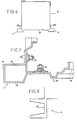
- FIGS. 6 and 7 illustrate an alternative embodiment of this mast (2) according to which the face of the mast (2), along which the cabin (6) moves, is composed of sheet metal panels (27), each, between its central core constituting the aforementioned face and each of its longitudinal assembly edges (27a) and (27b), has a raceway, respectively (4) and (5) identical to the raceways (4) and (5) of the example illustrated by FIGS. 2 to 4.
- This arrangement reduces the number of parts to be assembled in the corresponding angles of the mast (2), but requires that the panels (27) constituting the face considered of the mast (2 ) are different from the panels (11) constituting its three other faces.
- the holes for the passage of the assembly bolts (14) are advantageously located in frustoconical bowls, as illustrated in FIG. 7 in order, as in the previous example, to relieve the bolts (14) shear forces.
- FIG. 8 shows an alternative embodiment of the raceways (4) and (5) according to which the track (19) of each raceway (4) and (5) is shaped so as to have a trapezoidal section, at instead of being flat, so that the support rollers (21) and retaining (22) and the tracks (17) and (18) corresponding thereto, can be deleted.
- the panels (11) and possibly (27), forming part of the mast (2) are advantageously perforated by windows, respectively (28) and (29) having the effect, not only to lighten them, but also to reduce their wind resistance.
- each of them has one or more bosses (31) allowing the fixing of the rack (8) without it being necessary to provide spacers forming spacers, as well as stiffening ribs (32).
Landscapes
- Engineering & Computer Science (AREA)
- Structural Engineering (AREA)
- Civil Engineering (AREA)
- Transportation (AREA)
- Automation & Control Theory (AREA)
- Cage And Drive Apparatuses For Elevators (AREA)
- Types And Forms Of Lifts (AREA)
- Lift-Guide Devices, And Elevator Ropes And Cables (AREA)
- Tents Or Canopies (AREA)
- Load-Engaging Elements For Cranes (AREA)
- Joining Of Building Structures In Genera (AREA)
Claims (9)
Priority Applications (1)
| Application Number | Priority Date | Filing Date | Title |
|---|---|---|---|
| AT83420080T ATE15177T1 (de) | 1982-05-11 | 1983-05-04 | Bauaufzug. |
Applications Claiming Priority (2)
| Application Number | Priority Date | Filing Date | Title |
|---|---|---|---|
| FR8208740 | 1982-05-11 | ||
| FR8208740A FR2526774B1 (fr) | 1982-05-11 | 1982-05-11 | Elevateur de chantier |
Publications (2)
| Publication Number | Publication Date |
|---|---|
| EP0094894A1 EP0094894A1 (de) | 1983-11-23 |
| EP0094894B1 true EP0094894B1 (de) | 1985-08-28 |
Family
ID=9274176
Family Applications (1)
| Application Number | Title | Priority Date | Filing Date |
|---|---|---|---|
| EP83420080A Expired EP0094894B1 (de) | 1982-05-11 | 1983-05-04 | Bauaufzug |
Country Status (6)
| Country | Link |
|---|---|
| US (1) | US4557353A (de) |
| EP (1) | EP0094894B1 (de) |
| JP (1) | JPS58202276A (de) |
| AT (1) | ATE15177T1 (de) |
| DE (1) | DE3360661D1 (de) |
| FR (1) | FR2526774B1 (de) |
Cited By (1)
| Publication number | Priority date | Publication date | Assignee | Title |
|---|---|---|---|---|
| CN102765651A (zh) * | 2012-08-05 | 2012-11-07 | 荆州市荆工机械有限公司 | 驱动机构置于吊笼顶部并与吊笼为整体结构的人货两用施工升降机 |
Families Citing this family (35)
| Publication number | Priority date | Publication date | Assignee | Title |
|---|---|---|---|---|
| AT382849B (de) * | 1984-03-13 | 1987-04-10 | Ebbs & Radinger Maschhandel | Kabine zur personen- und lastenbefoerderung bei einem bauaufzug |
| US4804308A (en) * | 1987-01-20 | 1989-02-14 | Motor Coach Industries | Wheelchair lift |
| DE4113152A1 (de) * | 1991-04-23 | 1992-10-29 | Langer Ruth Geb Layher | Aufzug fuer baumaterialien, geruestelemente und geruestmontagen |
| US5253734A (en) * | 1992-03-11 | 1993-10-19 | Laurutis Charles J | High rise emergency elevator |
| US6079520A (en) * | 1995-04-07 | 2000-06-27 | Infinite Access Corporation | Method of retro-fitting elevators to existing buildings |
| US5626208A (en) * | 1995-07-13 | 1997-05-06 | Sprague; Randy L. | Lift assembly |
| DE19627549A1 (de) * | 1995-09-22 | 1997-03-27 | Paul Lingen | Mast für ein Baugerüst oder einen Baulift |
| US5927440A (en) * | 1996-09-11 | 1999-07-27 | Freeman; Glen D. | Mobile hoist system and method |
| KR100260648B1 (ko) * | 1997-11-27 | 2000-12-01 | 노희상 | 건축 공사용 안전 펜스 |
| WO1999040013A1 (fr) * | 1998-02-06 | 1999-08-12 | Jetwey Technology Corporation Limited | Dispositif de levage |
| US6779634B1 (en) * | 1999-12-06 | 2004-08-24 | Wayne M. Slagle | Dumb waiter elevating and lowering platform device |
| US6640934B1 (en) * | 2000-05-01 | 2003-11-04 | Ricky L. Edwards | Residential cargo lift |
| US20020139619A1 (en) * | 2000-05-16 | 2002-10-03 | Minglun Qiu | Hoistwayless elevator system |
| ES2170680B1 (es) * | 2000-07-06 | 2004-01-01 | Ttv Madrid S L | Estructura de cerramiento desmontable para ascensores. |
| KR100371052B1 (ko) * | 2000-08-05 | 2003-02-06 | 주식회사 이성건설기계 | 승강기 |
| KR20020033672A (ko) * | 2002-02-23 | 2002-05-07 | 백수곤 | 붐 호이스트 |
| US20030178259A1 (en) * | 2002-03-25 | 2003-09-25 | Henderson Russell Peter | Goods lift mechanism |
| DE10297757T5 (de) * | 2002-06-20 | 2005-06-30 | Otis Elevator Co., Farmington | Sicherheitsaufbaubalustrade für eine Kabine eines Maschinenraum-losen Aufzugs |
| US7392624B2 (en) * | 2003-02-05 | 2008-07-01 | Dwight Eric Kinzer | Modular load-bearing structural column |
| US20060196735A1 (en) * | 2005-03-07 | 2006-09-07 | Waupaca Elevator Company, Inc. | Frameless elevator cab and methods |
| FR2894237B1 (fr) * | 2005-12-02 | 2009-05-29 | Manuel Machado | Nacelle a mecanisme de propulsion et de securite embarque |
| ES2283217B1 (es) * | 2006-04-11 | 2009-02-16 | Elevadores Goian S.L. | Ascensor modular con cabina automotriz sobre mastil. |
| US8020667B2 (en) * | 2006-04-21 | 2011-09-20 | Dennis Johnson | Lift apparatus |
| US20080099283A1 (en) * | 2006-10-25 | 2008-05-01 | Robert Jacobus Reigwein | Lift Apparatus and Method for Forming Same |
| US20080230321A1 (en) * | 2007-03-19 | 2008-09-25 | Frank Csaszar | Portable freestanding elevator |
| US20090129905A1 (en) * | 2007-11-20 | 2009-05-21 | International Business Machines Corporation | Portable end-to-end installation and removal service lift tool for rack mounted it equipment |
| US20090282747A1 (en) * | 2008-05-14 | 2009-11-19 | Epp Richard J | Grain bin with person elevator |
| NL2001941C (nl) * | 2008-08-29 | 2010-03-11 | Houtveen Beheer Achterveld B V | Voertuiglift. |
| GB0907333D0 (en) * | 2009-04-29 | 2009-06-10 | Adams William M | Lifting apparatus |
| US10597274B1 (en) * | 2011-11-15 | 2020-03-24 | Homecare Products, Inc. | Tower elevating assembly |
| JP5686121B2 (ja) * | 2012-07-26 | 2015-03-18 | 村田機械株式会社 | スタッカクレーン |
| JP6256420B2 (ja) * | 2015-06-30 | 2018-01-10 | 村田機械株式会社 | スタッカクレーン |
| WO2018139924A2 (en) * | 2017-01-24 | 2018-08-02 | Raxtar B.V. | Construction elevator |
| TWI620705B (zh) * | 2017-05-02 | 2018-04-11 | He cheng yu | 升降式樓梯結構 |
| WO2021237049A1 (en) * | 2020-05-21 | 2021-11-25 | The Tisdale Group, LLC | Mast climber |
Family Cites Families (13)
| Publication number | Priority date | Publication date | Assignee | Title |
|---|---|---|---|---|
| US498859A (en) * | 1893-06-06 | Niels poulson | ||
| US1552474A (en) * | 1920-11-20 | 1925-09-08 | Dornier Claude | Hollow metal beam |
| GB285037A (en) * | 1927-02-09 | 1928-07-05 | Hans Kasch | Improvements in masts for apparatus for hoisting and pouring concrete |
| FR1568824A (de) * | 1967-12-05 | 1969-05-30 | ||
| US3517774A (en) * | 1968-01-17 | 1970-06-30 | Roy E Meyer | Tower elevator |
| CH536788A (de) * | 1970-12-29 | 1973-05-15 | Theresia Rompa Jozef Johannes | Gegen einen im wesentlichen senkrechten Bauteil anzustellender Aufzug |
| AT315419B (de) * | 1971-12-03 | 1974-05-27 | Alois Krasser | Rohrförmiger Stahlmast für Bauaufzüge |
| US3820906A (en) * | 1972-08-10 | 1974-06-28 | H Katt | Highway sign post |
| US3878916A (en) * | 1973-02-07 | 1975-04-22 | Jr Gerome R White | Rack and pinion drive counterbalanced hoist systems |
| GB1474559A (en) * | 1974-04-26 | 1977-05-25 | Ace Machinery Ltd | Tower particularly for a hoist |
| FR2293893A1 (fr) * | 1974-12-12 | 1976-07-09 | Telemecanique Electrique | Ossature pour armoire metallique |
| US4262773A (en) * | 1979-07-13 | 1981-04-21 | Basham Billy G | Portable scaffold |
| US4248025A (en) * | 1979-08-08 | 1981-02-03 | Unarco Industries, Inc. | Knock down pole construction |
-
1982
- 1982-05-11 FR FR8208740A patent/FR2526774B1/fr not_active Expired
-
1983
- 1983-05-04 EP EP83420080A patent/EP0094894B1/de not_active Expired
- 1983-05-04 AT AT83420080T patent/ATE15177T1/de not_active IP Right Cessation
- 1983-05-04 DE DE8383420080T patent/DE3360661D1/de not_active Expired
- 1983-05-11 US US06/493,743 patent/US4557353A/en not_active Expired - Fee Related
- 1983-05-11 JP JP58081032A patent/JPS58202276A/ja active Pending
Cited By (1)
| Publication number | Priority date | Publication date | Assignee | Title |
|---|---|---|---|---|
| CN102765651A (zh) * | 2012-08-05 | 2012-11-07 | 荆州市荆工机械有限公司 | 驱动机构置于吊笼顶部并与吊笼为整体结构的人货两用施工升降机 |
Also Published As
| Publication number | Publication date |
|---|---|
| FR2526774A1 (fr) | 1983-11-18 |
| DE3360661D1 (en) | 1985-10-03 |
| ATE15177T1 (de) | 1985-09-15 |
| EP0094894A1 (de) | 1983-11-23 |
| US4557353A (en) | 1985-12-10 |
| FR2526774B1 (fr) | 1986-03-07 |
| JPS58202276A (ja) | 1983-11-25 |
Similar Documents
| Publication | Publication Date | Title |
|---|---|---|
| EP0094894B1 (de) | Bauaufzug | |
| EP0085608B1 (de) | Verfahren und Vorrichtung zur Erstellung eines Brückenoberbaus und ähnlicher Bauten, sowie auf diese Art und Weise erstellte Bauwerke | |
| DE19757204C1 (de) | Fahrzeugzelle | |
| EP2674538A1 (de) | Modulkonstruktion und entsprechendes Verfahren zum Zusammenbau | |
| CA2728857A1 (en) | Decking having a removable rib | |
| FR2606123A1 (fr) | Lisse profilee destinee a supporter des charges, notamment pour casiers de stockage | |
| EP0864702B1 (de) | Traggerüst für Gebäude hergestellt von kaltgewalzten Profilen | |
| FR2565565A1 (fr) | Tapis a billes pour recevoir et transferer des charges pour gagner du poids dans des applications aux avions | |
| EP0323293B1 (de) | Vorrichtung zum Wägen von Fahrzeugen | |
| EP0194949B1 (de) | Allgemein nützliches Gebäude, insbesondere Kaufhalle | |
| EP0593365B1 (de) | Als Brückenteil ausgebildeter horizontaler Träger | |
| EP0712970B1 (de) | Fassadenstruktur für Gebaüde oder ähnliche Strukturen | |
| EP0440567A1 (de) | Einzelne und doppelte Träger und Pfosten, bestehend aus der Zusammensetzung von Z-Trägern, die insbesondere die Realisierung eines Rahmens oder einer Kniestütze für den Bau eines Gebäudes erlauben | |
| EP3931405A1 (de) | Modulare metallstruktur | |
| FR2614054A1 (fr) | Procede de construction de parois de batiments | |
| EP0193689B1 (de) | Vorgefertigtes Ständerwerk für die Herstellung von Wänden | |
| JPS5923147Y2 (ja) | ベランダ等における安全柵 | |
| EP0221217A1 (de) | Entfaltbares Holzgerippe | |
| FR2754005A1 (fr) | Tribunes et gradins demontables et procede de renforcement des tribunes et gradins | |
| FR2585048A1 (fr) | Construction prefabriquee | |
| FR2627528A1 (fr) | Ensemble d'elements pour la realisation d'auvents a trois pentes a caractere modulaire | |
| FR2484495A1 (fr) | Procede de montage d'une structure d'ouvrage d'art telle qu'une passerelle metallique et structures ainsi obtenues | |
| WO2021099734A1 (fr) | Structure métallique modulaire | |
| FR2513288A1 (fr) | Dispositif d'assemblage de panneaux de construction et panneaux equipes pour etre assembles a l'aide de ce dispositif | |
| FR2991696A1 (fr) | Ossature de plancher pour construction de preference modulaire |
Legal Events
| Date | Code | Title | Description |
|---|---|---|---|
| PUAI | Public reference made under article 153(3) epc to a published international application that has entered the european phase |
Free format text: ORIGINAL CODE: 0009012 |
|
| AK | Designated contracting states |
Designated state(s): AT BE CH DE GB IT LI LU NL SE |
|
| 17P | Request for examination filed |
Effective date: 19831014 |
|
| ITF | It: translation for a ep patent filed | ||
| GRAA | (expected) grant |
Free format text: ORIGINAL CODE: 0009210 |
|
| AK | Designated contracting states |
Designated state(s): AT BE CH DE GB IT LI LU NL SE |
|
| REF | Corresponds to: |
Ref document number: 15177 Country of ref document: AT Date of ref document: 19850915 Kind code of ref document: T |
|
| REF | Corresponds to: |
Ref document number: 3360661 Country of ref document: DE Date of ref document: 19851003 |
|
| PG25 | Lapsed in a contracting state [announced via postgrant information from national office to epo] |
Ref country code: AT Effective date: 19860504 |
|
| PG25 | Lapsed in a contracting state [announced via postgrant information from national office to epo] |
Ref country code: SE Effective date: 19860505 |
|
| PG25 | Lapsed in a contracting state [announced via postgrant information from national office to epo] |
Ref country code: LU Free format text: LAPSE BECAUSE OF NON-PAYMENT OF DUE FEES Effective date: 19860531 Ref country code: LI Effective date: 19860531 Ref country code: CH Effective date: 19860531 Ref country code: BE Effective date: 19860531 |
|
| PLBE | No opposition filed within time limit |
Free format text: ORIGINAL CODE: 0009261 |
|
| STAA | Information on the status of an ep patent application or granted ep patent |
Free format text: STATUS: NO OPPOSITION FILED WITHIN TIME LIMIT |
|
| 26N | No opposition filed | ||
| BERE | Be: lapsed |
Owner name: PICHON MICHEL ALAIN Effective date: 19860531 |
|
| PG25 | Lapsed in a contracting state [announced via postgrant information from national office to epo] |
Ref country code: NL Effective date: 19861201 |
|
| NLV4 | Nl: lapsed or anulled due to non-payment of the annual fee | ||
| REG | Reference to a national code |
Ref country code: CH Ref legal event code: PL |
|
| PG25 | Lapsed in a contracting state [announced via postgrant information from national office to epo] |
Ref country code: DE Effective date: 19870203 |
|
| GBPC | Gb: european patent ceased through non-payment of renewal fee | ||
| PG25 | Lapsed in a contracting state [announced via postgrant information from national office to epo] |
Ref country code: GB Free format text: LAPSE BECAUSE OF NON-PAYMENT OF DUE FEES Effective date: 19881122 |
|
| EUG | Se: european patent has lapsed |
Ref document number: 83420080.0 Effective date: 19870225 |