EP0193689B1 - Vorgefertigtes Ständerwerk für die Herstellung von Wänden - Google Patents
Vorgefertigtes Ständerwerk für die Herstellung von Wänden Download PDFInfo
- Publication number
- EP0193689B1 EP0193689B1 EP19850400435 EP85400435A EP0193689B1 EP 0193689 B1 EP0193689 B1 EP 0193689B1 EP 19850400435 EP19850400435 EP 19850400435 EP 85400435 A EP85400435 A EP 85400435A EP 0193689 B1 EP0193689 B1 EP 0193689B1
- Authority
- EP
- European Patent Office
- Prior art keywords
- posts
- arms
- strake
- arm
- frame according
- Prior art date
- Legal status (The legal status is an assumption and is not a legal conclusion. Google has not performed a legal analysis and makes no representation as to the accuracy of the status listed.)
- Expired - Lifetime
Links
- 238000010276 construction Methods 0.000 title description 6
- 210000000078 claw Anatomy 0.000 claims description 5
- 239000002023 wood Substances 0.000 description 6
- 238000005192 partition Methods 0.000 description 3
- 238000004873 anchoring Methods 0.000 description 2
- 238000009826 distribution Methods 0.000 description 2
- 238000006073 displacement reaction Methods 0.000 description 1
- 238000009434 installation Methods 0.000 description 1
- 238000005304 joining Methods 0.000 description 1
- 238000004519 manufacturing process Methods 0.000 description 1
- 239000002184 metal Substances 0.000 description 1
- 238000000034 method Methods 0.000 description 1
- 235000019640 taste Nutrition 0.000 description 1
Images



Classifications
-
- E—FIXED CONSTRUCTIONS
- E04—BUILDING
- E04C—STRUCTURAL ELEMENTS; BUILDING MATERIALS
- E04C2/00—Building elements of relatively thin form for the construction of parts of buildings, e.g. sheet materials, slabs, or panels
- E04C2/30—Building elements of relatively thin form for the construction of parts of buildings, e.g. sheet materials, slabs, or panels characterised by the shape or structure
- E04C2/40—Building elements of relatively thin form for the construction of parts of buildings, e.g. sheet materials, slabs, or panels characterised by the shape or structure composed of a number of smaller components rigidly or movably connected together, e.g. interlocking, hingedly connected of particular shape, e.g. not rectangular of variable shape or size, e.g. flexible or telescopic panels
-
- E—FIXED CONSTRUCTIONS
- E04—BUILDING
- E04C—STRUCTURAL ELEMENTS; BUILDING MATERIALS
- E04C2/00—Building elements of relatively thin form for the construction of parts of buildings, e.g. sheet materials, slabs, or panels
- E04C2/30—Building elements of relatively thin form for the construction of parts of buildings, e.g. sheet materials, slabs, or panels characterised by the shape or structure
- E04C2/38—Building elements of relatively thin form for the construction of parts of buildings, e.g. sheet materials, slabs, or panels characterised by the shape or structure with attached ribs, flanges, or the like, e.g. framed panels
- E04C2/386—Building elements of relatively thin form for the construction of parts of buildings, e.g. sheet materials, slabs, or panels characterised by the shape or structure with attached ribs, flanges, or the like, e.g. framed panels with a frame of unreconstituted or laminated wood
Definitions
- the present invention relates to a prefabricated framework for the construction of walls, more particularly although not exclusively partitions or walls, this framework comprising a plurality of spaced uprights, to which are articulated arms.
- Skeletons of this type are known, for example from GB-A-155 682, DE-A-385 976, DE-A-868 508, GB-A-786 884 and NL-A-72 07690.
- said articulated arms connect the uprights together so that two or more consecutive uprights form, with the associated arms, a deformable parallelogram.
- foldable frames are obtained which can be prefabricated in the factory and deployable on the site, in order to form the frame of a wall to be constructed.
- this foldable and deployable part a low rail and a high rail, to which the ends of said uprights are connected, which are then arranged vertically.
- Such frames are widely used because they greatly simplify the construction of buildings, and in particular of individual houses. However, they have drawbacks, generally due to their insufficient rigidity.
- the vertical uprights of a frame are regularly distributed according to a modular spacing, which does not necessarily correspond optimally to the distribution of vertical loads which are exerted on the frame.
- a high beam in particular when a large load is applied between two uprights, instead of being applied vertically to one of them, this results in warping of said frame.
- This drawback is aggravated by the fact that the modular spacing between two vertical uprights is generally smaller than the width of the openings which must be made in the wall for the installation of windows or doors.
- the modular framework must be interrupted at these locations, which further disrupts the distribution of the loads exerted on the wall and the risks of warping or buckling of the framework.
- any displacement of such an opening relative to a standard position of a standard framework for example to satisfy the personal tastes of a customer having his house built, entails a practically complete recalculation of said framework, to be sure that it will be able to resist the loads which will be applied to it.
- the object of the present invention is to remedy these drawbacks by making it possible to considerably increase the rigidity of such a framework.
- the prefabricated framework for the construction of walls, in particular partitions or walls, comprising on the one hand, a plurality of uprights parallel to each other and to each of which are articulated arms, and on the other hand, a high rail and a low rail to which the ends of said uprights are connected, is remarkable in that at each of said uprights is articulated at least one arm at its upper part and at least one arm at its lower part, the length of said arms being less than the spacing between two consecutive uprights and the respective articulation points being set back relative to the upper and lower ends of the upright and in that the free end of each upper arm and the free end of each lower arm are respectively connected to the top rail and the bottom rail at points arranged between two consecutive uprights.
- the assembly of the upper arm and the upper arms on the one hand, and the assembly of the lower arm and the lower arms, on the other hand, form lattice beams giving great rigidity to the mounted frame.
- the beam formed by the assembly of the top rail and the upper arms constitutes, with the rest of the framework, a real gantry.
- each upright except possibly the end uprights, comprises two upper arms and two lower arms, an upper arm and a lower arm being connected respectively to the upper heald and to the lower heald on one side of said corresponding upright, while the other upper arm and the other lower arm are respectively connected to the upper rail and to the lower rail on the other side of said upright.
- the upper arms and the lower arms respectively directed towards one another and belonging to two consecutive uprights are connected in common to the top rail and to the bottom rail, at a midpoint of the spacing between said amounts.
- ends of said upper and lower arms are shaped to bear, respectively on the top rail and on the bottom rail.
- connections between the healds and the uprights, on the one hand, and between the healds and the arms, on the other hand are produced by means of dowels, tenons or the like, passing through pre-drilled holes or mortises in said healds. and said uprights and arms.
- the prefabricated frame according to the invention may be in the form of an assembly comprising a top rail, a bottom rail and a plurality of separate individual uprights, each provided with its arms.
- this prefabricated framework may be in the form of an assembly comprising a top rail, a bottom rail and a deployable portion consisting of a plurality of uprights, each provided with its arms, the upper arms facing the two uprights consecutive being hinged to each other by their ends and the lower arms facing two consecutive uprights also being hinged to each other by their ends.
- amounts are provided each consisting of two parallel wooden posts and secured by claw connectors and the ends of said arms articulated to an amount are located between the posts thereof.
- bracing means arranged between said posts.
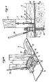
- the portion 1 of prefabricated framework for the construction of walls, in accordance with the invention and represented in FIG. 1, comprises a plurality of uprights 2, parallel and regularly spaced apart by a distance D, a high rail 3 and a low rail 4.
- Each upright 2 consists, as explained in French patent applications No. 2501807 and No. 2542048, of two wooden posts 5, parallel and spaced, assembled to each other by connectors with intermediate claws 6 and by end-claw connectors 7.
- the claw connectors 6 and 7 consist, in known manner, of metal plates, having zones 8 provided with stamped claws 9, forced into the posts 5.
- the end connectors 7 have a projection 10, beyond the end of said posts 5, but whose width is limited to the existing gap between the two posts 5.
- Each projection 10 has a passage 11, in a direction parallel to the plane defined by the posts 5.
- the rails 3 and 4 each consist of two horizontal pieces of wood 12, for example identical to the posts 5 and of square or rectangular section, assembled by an external strip 13.
- the strip 13 of the bottom rail 4 rests on a concrete base 14.
- the spacing of the pieces of wood 12 of a stringer 3 or 4 corresponds to the spacing of the posts 5 of an upright 2.
- the uprights 2 and the rails 3 and 4 are arranged so that the projections 10 of the end connectors 7 are housed in the cavity delimited by the pieces of wood 12 and the strips 13.
- the ends of each of the posts 5 are in contact of a piece of wood 12 of the top rail 3 or of the bottom rail 4, the plane defined by the two posts 5 of an upright 2 being transverse to the rails 3 and 4.
- the two pieces of wood 12 of the top rail 3 and the bottom rail 4 are pierced with a plurality of transverse holes 15 in correspondence, these holes 15 forming a series of regular steps.
- the ends of an upright 2 can be fixed to the top rails 3 and bottom 4 by means of transverse pins 16 passing through the pieces of wood 12 of said rails and the passage 11 of the end connectors 7.
- the posts 5 can also be pierced with a plurality of transverse holes 17 in correspondence, into which pegs 18 can be introduced for the fixing of stiffening beams 19, passing between the two posts of the uprights 2 and provided with a plurality of through holes 20, for the passage of the dowels 18, allowing the joining of the lon- gerons 19 and the uprights 20.
- each intermediate upright 2 are articulated at the upper part and at the lower part, two arms 21 which are located between the two posts of said upright and whose joints 22 (for example also of the type with pin) are set back from the corresponding end.
- the two end uprights may have only one arm 21 at their upper part and only one arm 21 at their lower part.
- each arm 21 is less than the spacing D between two consecutive uprights and, each time, an upper arm 21 of an upright 2 and an upper arm 21 of the neighboring upright 2 are joined to one another as well as the top rail 3, by their ends, at a point 23 equidistant from said uprights 2 consecutive. Likewise, each time, a lower arm 21 of an upright 2 and a lower arm 21 of the neighboring upright 2 are joined together, as well as at the bottom rail 4, by their ends, in a point 24 equidistant from the said 2 consecutive amounts.
- connection points 23 and 24 corresponding to holes 15 and the junctions at these points are carried out by means of pins 25 passing through the holes 5 and holes 26 made in the ends of the arms 21 simultaneously (see FIG. 7).
- ends of the arm 21 are each provided with a bevel 27 which bears against the internal face 13 of the strip 13 of the corresponding heddle 3 or 4.
- the assembly of a heddle 3 or 4 and of the arms 21 which are there. connected forms a lattice beam, ensuring great rigidity to the unfolded frame 1.
- the beam formed by the top rail 3 and the corresponding arms 21, forms with the rest of said frame, a gantry construction.
- the framework 1 is in the form of an assembly comprising a top rail 3, a bottom rail 4 and a plurality of separate uprights 2 each provided with their arms 21, articulated at 22.
- a top rail 3 a bottom rail 4
- a plurality of separate uprights 2 each provided with their arms 21, articulated at 22.
- the framework 1 is, if the beams 3 and 4 are excluded, in the form of a foldable assembly comprising a plurality of uprights 2 (including only two are shown in said figures), linked to each other by their arms 21, the opposite ends of which are articulated to each other, for example by means of a hollow axis 28, capable of being traversed subsequently by a pin 25 (see Figure 7).
- Figures 6a to 6e show different relative positions that can take two uprights 2 consecutive and their arms 21 cooperating.
- Bracing is provided by cables 29 anchored at their two ends to the end connectors 7 of different uprights 2 by means of fasteners 33 (see Figures 8, 9 and 10).
- the lower anchoring of said bracing cables 29 can be further reinforced by means of a dowel 30, itself anchored in the concrete foundation 14.
Landscapes
- Engineering & Computer Science (AREA)
- Architecture (AREA)
- Civil Engineering (AREA)
- Structural Engineering (AREA)
- Joining Of Building Structures In Genera (AREA)
Claims (9)
Priority Applications (4)
| Application Number | Priority Date | Filing Date | Title |
|---|---|---|---|
| FR8314521A FR2551788B1 (fr) | 1983-09-13 | 1983-09-13 | Ossature prefabriquee pour la construction de parois |
| AT85400435T ATE57220T1 (de) | 1985-03-06 | 1985-03-06 | Vorgefertigtes staenderwerk fuer die herstellung von waenden. |
| EP19850400435 EP0193689B1 (de) | 1983-09-13 | 1985-03-06 | Vorgefertigtes Ständerwerk für die Herstellung von Wänden |
| DE8585400435T DE3580028D1 (de) | 1985-03-06 | 1985-03-06 | Vorgefertigtes staenderwerk fuer die herstellung von waenden. |
Applications Claiming Priority (2)
| Application Number | Priority Date | Filing Date | Title |
|---|---|---|---|
| FR8314521A FR2551788B1 (fr) | 1983-09-13 | 1983-09-13 | Ossature prefabriquee pour la construction de parois |
| EP19850400435 EP0193689B1 (de) | 1983-09-13 | 1985-03-06 | Vorgefertigtes Ständerwerk für die Herstellung von Wänden |
Publications (2)
| Publication Number | Publication Date |
|---|---|
| EP0193689A1 EP0193689A1 (de) | 1986-09-10 |
| EP0193689B1 true EP0193689B1 (de) | 1990-10-03 |
Family
ID=26099908
Family Applications (1)
| Application Number | Title | Priority Date | Filing Date |
|---|---|---|---|
| EP19850400435 Expired - Lifetime EP0193689B1 (de) | 1983-09-13 | 1985-03-06 | Vorgefertigtes Ständerwerk für die Herstellung von Wänden |
Country Status (2)
| Country | Link |
|---|---|
| EP (1) | EP0193689B1 (de) |
| FR (1) | FR2551788B1 (de) |
Families Citing this family (2)
| Publication number | Priority date | Publication date | Assignee | Title |
|---|---|---|---|---|
| FR2551788B1 (fr) * | 1983-09-13 | 1987-02-20 | Vaslier Yves | Ossature prefabriquee pour la construction de parois |
| ITNO20130004A1 (it) | 2013-06-03 | 2014-12-04 | Mauro Sica | Sistema di pre-distanziamento collassabile particolarmente per gli elementi di un telaio strutturale |
Family Cites Families (8)
| Publication number | Priority date | Publication date | Assignee | Title |
|---|---|---|---|---|
| GB155682A (en) * | 1919-10-14 | 1920-12-30 | Gustave Robert Speaker | Improvements in building frames |
| DE385976C (de) * | 1920-10-23 | 1923-12-01 | Hans Zamecznik | Verfahren zur Herstellung des Traggerippes flaechenartiger Bauteile, wie Waende, Decken, Daecher |
| US1607166A (en) * | 1925-08-03 | 1926-11-16 | Mccall Benjamin Bartley | Building construction |
| FR865406A (fr) * | 1940-01-24 | 1941-05-23 | Perfectionnements aux maisons en bois | |
| DE868508C (de) * | 1950-03-17 | 1953-02-26 | Henry Dipl-Ing Lutz | Herstellung von Wandskeletten, Decken und Daechern fuer Hoch- und Tiefbauten |
| GB786884A (en) * | 1953-02-07 | 1957-11-27 | James Richard Dartford | Improvements in or relating to structural systems and parts for buildings |
| NL7207690A (de) * | 1972-06-07 | 1973-12-11 | ||
| FR2551788B1 (fr) * | 1983-09-13 | 1987-02-20 | Vaslier Yves | Ossature prefabriquee pour la construction de parois |
-
1983
- 1983-09-13 FR FR8314521A patent/FR2551788B1/fr not_active Expired
-
1985
- 1985-03-06 EP EP19850400435 patent/EP0193689B1/de not_active Expired - Lifetime
Also Published As
| Publication number | Publication date |
|---|---|
| FR2551788B1 (fr) | 1987-02-20 |
| EP0193689A1 (de) | 1986-09-10 |
| FR2551788A1 (fr) | 1985-03-15 |
Similar Documents
| Publication | Publication Date | Title |
|---|---|---|
| EP0118374B1 (de) | Bausystem mit verlorener Schalung | |
| EP0174257B1 (de) | System aus Holzelementen für Bausatzmöbel | |
| EP3323951B1 (de) | Modulare strukturplatte und anordnung, die solche platten für den bau eines gebäudes umfasst | |
| EP0094894A1 (de) | Bauaufzug | |
| CA2398882A1 (fr) | Profile de structure, notamment pour cloisons | |
| EP0063662B1 (de) | Vorgefertigte Einheit zur Herstellung eines Baugerüstes | |
| BE1011185A5 (fr) | Ossature de batiment. | |
| EP0193689A1 (de) | Vorgefertigtes Ständerwerk für die Herstellung von Wänden | |
| WO2008145856A2 (fr) | Element d'assemblage d'angle pour coffrage et coffrage ainsi obtenu | |
| FR2907478A1 (fr) | Nouvel assemblage de profiles en bois ou en materiau de synthese au moyen de pieces de jonction metalliques | |
| EP0152145A1 (de) | Platte für den Bau eines Hauses im Baukastensystem | |
| US20050144859A1 (en) | Construction kit | |
| FR2529928A1 (fr) | Batiment modulaire pliable | |
| EP0115371A2 (de) | Baupaneel aus Holz | |
| FR2993296A1 (fr) | Abri demontable | |
| FR2570748A1 (fr) | Dispositif d'assemblage simplifie des differentes parties de fenetres, portes et ouvertures similaires, en bois, ainsi que tout agencement de meubles | |
| FR2586732A1 (fr) | Ensemble de construction pour la realisation de cloisons ou de parois modulaires | |
| FR2650611A1 (fr) | Ossature en bois pour la realisation de murs ou parois d'une construction et construction obtenue a partir de ladite ossature | |
| EP0701646B1 (de) | Profil für ein sandwichförmiges wandtragendes paneel, paneel mit einem solchen profil und konstruktion mit einem solchen paneel | |
| FR2739640A1 (fr) | Procede de construction d'une maison a ossature bois | |
| FR2627528A1 (fr) | Ensemble d'elements pour la realisation d'auvents a trois pentes a caractere modulaire | |
| FR2523183A1 (fr) | Systeme de construction de maisons a ossature bois | |
| JPH0350218Y2 (de) | ||
| FR2641809A1 (fr) | Dispositif d'assemblage pour ossature de cloisons | |
| CA2063298C (fr) | Construction de plancher |
Legal Events
| Date | Code | Title | Description |
|---|---|---|---|
| PUAI | Public reference made under article 153(3) epc to a published international application that has entered the european phase |
Free format text: ORIGINAL CODE: 0009012 |
|
| 17P | Request for examination filed |
Effective date: 19860310 |
|
| AK | Designated contracting states |
Kind code of ref document: A1 Designated state(s): AT BE CH DE GB IT LI LU NL SE |
|
| 17Q | First examination report despatched |
Effective date: 19880426 |
|
| GRAA | (expected) grant |
Free format text: ORIGINAL CODE: 0009210 |
|
| AK | Designated contracting states |
Kind code of ref document: B1 Designated state(s): AT BE CH DE GB IT LI LU NL SE |
|
| PG25 | Lapsed in a contracting state [announced via postgrant information from national office to epo] |
Ref country code: IT Free format text: LAPSE BECAUSE OF FAILURE TO SUBMIT A TRANSLATION OF THE DESCRIPTION OR TO PAY THE FEE WITHIN THE PRESCRIBED TIME-LIMIT;WARNING: LAPSES OF ITALIAN PATENTS WITH EFFECTIVE DATE BEFORE 2007 MAY HAVE OCCURRED AT ANY TIME BEFORE 2007. THE CORRECT EFFECTIVE DATE MAY BE DIFFERENT FROM THE ONE RECORDED. Effective date: 19901003 Ref country code: AT Effective date: 19901003 Ref country code: SE Effective date: 19901003 Ref country code: NL Effective date: 19901003 Ref country code: GB Effective date: 19901003 |
|
| REF | Corresponds to: |
Ref document number: 57220 Country of ref document: AT Date of ref document: 19901015 Kind code of ref document: T |
|
| REF | Corresponds to: |
Ref document number: 3580028 Country of ref document: DE Date of ref document: 19901108 |
|
| NLV1 | Nl: lapsed or annulled due to failure to fulfill the requirements of art. 29p and 29m of the patents act | ||
| PG25 | Lapsed in a contracting state [announced via postgrant information from national office to epo] |
Ref country code: LU Free format text: LAPSE BECAUSE OF NON-PAYMENT OF DUE FEES Effective date: 19910331 Ref country code: CH Effective date: 19910331 Ref country code: LI Effective date: 19910331 Ref country code: BE Effective date: 19910331 |
|
| GBV | Gb: ep patent (uk) treated as always having been void in accordance with gb section 77(7)/1977 [no translation filed] | ||
| PLBE | No opposition filed within time limit |
Free format text: ORIGINAL CODE: 0009261 |
|
| STAA | Information on the status of an ep patent application or granted ep patent |
Free format text: STATUS: NO OPPOSITION FILED WITHIN TIME LIMIT |
|
| 26N | No opposition filed | ||
| BERE | Be: lapsed |
Owner name: VASLIER YVES RAOUL Effective date: 19910331 |
|
| REG | Reference to a national code |
Ref country code: CH Ref legal event code: PL |
|
| PG25 | Lapsed in a contracting state [announced via postgrant information from national office to epo] |
Ref country code: DE Effective date: 19920101 |