EP0095095A1 - Procédé par le pesage de matière en vrac et dispositif de pesage - Google Patents
Procédé par le pesage de matière en vrac et dispositif de pesage Download PDFInfo
- Publication number
- EP0095095A1 EP0095095A1 EP83104677A EP83104677A EP0095095A1 EP 0095095 A1 EP0095095 A1 EP 0095095A1 EP 83104677 A EP83104677 A EP 83104677A EP 83104677 A EP83104677 A EP 83104677A EP 0095095 A1 EP0095095 A1 EP 0095095A1
- Authority
- EP
- European Patent Office
- Prior art keywords
- metering
- belt
- weighing
- fine
- stream
- Prior art date
- Legal status (The legal status is an assumption and is not a legal conclusion. Google has not performed a legal analysis and makes no representation as to the accuracy of the status listed.)
- Withdrawn
Links
Images

Classifications
-
- G—PHYSICS
- G01—MEASURING; TESTING
- G01G—WEIGHING
- G01G13/00—Weighing apparatus with automatic feed or discharge for weighing-out batches of material
- G01G13/02—Means for automatically loading weigh pans or other receptacles, e.g. disposable containers, under control of the weighing mechanism
- G01G13/022—Material feeding devices
- G01G13/026—Material feeding devices by mechanical conveying means, e.g. belt or vibratory conveyor
-
- G—PHYSICS
- G01—MEASURING; TESTING
- G01G—WEIGHING
- G01G13/00—Weighing apparatus with automatic feed or discharge for weighing-out batches of material
- G01G13/02—Means for automatically loading weigh pans or other receptacles, e.g. disposable containers, under control of the weighing mechanism
- G01G13/04—Means for automatically loading weigh pans or other receptacles, e.g. disposable containers, under control of the weighing mechanism involving dribble-feed means controlled by the weighing mechanism to top up the receptacle to the target weight
- G01G13/08—Means for automatically loading weigh pans or other receptacles, e.g. disposable containers, under control of the weighing mechanism involving dribble-feed means controlled by the weighing mechanism to top up the receptacle to the target weight wherein the main feed is effected by mechanical conveying means, e.g. by belt conveyors, by vibratory conveyors
Definitions
- the invention relates to a method for weighing bulk goods, the bulk goods being fed to a weighing container via a metering belt.
- the invention further relates to a weighing device with a metering belt, a shut-off device which can be controlled by a balance and a balance container.
- a large part of the bulk food and feed is transported in bags and at least temporarily stored in them.
- the sack offers the advantage of scheduling for the individual customer. Any subset that can be divided by a standard bag weight can be supplied to the individual consumers via a transport system.
- the disadvantage of the bulk transport of bulk goods lies in the effort involved in filling and weighing, which is to be carried out for each individual bag at high speed.
- the experts involved are striving to carry out bagging as efficiently as possible, but especially as quickly as possible. It is obvious that several opposing issues must be combined in one system. In the foreground are e.g. the three criteria of speed, accuracy and investment for the entire bagging system.
- the scale devices are regularly checked so that they do not deviate from the calibration requirements.
- Two systems are predominant for the bagging of food and feed.
- screw feeding a coarse and a fine flow is formed for larger industrial plants in order to optimally utilize the entire bagging and weighing mechanism, via a correspondingly large or small screw.
- the scale container can be almost filled with high output, in order to then end the exact dosing phase with the small dosing screw.
- Snail feeds can be used where there is a relatively high consistency in the bulk properties, e.g. when bagging meal or bread flour. In flour mills you will mainly find snail feeds for dosing the scales. A much larger variety of products is common in the field of feed mills: feed cubes, feed flakes, feed bran and feed flour, partly mineral components, etc.
- Dosing belts are mainly used for these product classes.
- a metering belt naturally requires a relatively large amount of construction work compared to the screw conveyor.
- the object on which the invention is based is to improve a method of the type mentioned at the outset in such a way that a substantial increase in bagging capacity, for example to 600 to 800 bags per hour, is possible with unchanged metering accuracy even without using a feed screw feeder, but with the Dosing transport is as gentle on the product as with known dosing belt guides.
- this is achieved in a method of the type mentioned at the outset in that the feed quantity of the metering belt is divided into a main metering stream and a fine metering stream and that the main metering stream can be introduced into a collecting container in which the corresponding bulk material is stored and from which it is independent of the fine metering stream is fed back into the main metering flow during the next weighing process.
- the invention enables the underlying task to be solved very advantageously by the simplest means by combinatorial interaction.
- the metering belt normally provides constant performance: by dividing the feed quantity of the belt into a main metering stream and a fine metering stream, the metering function can be designed according to optimal criteria. At the same time, the feed quantity can be set to a maximum during the rough dosing phase.
- the essential change in momentum (stopping the product falling into the weighing container) after the coarse dosing has ended has an effect in the fine dosing phase, so that the fine dosing can already be used to calm the balance.
- the belt By briefly accumulating or temporarily storing the coarse flow in the fine metering phase, the belt can (at least theoretically) run at maximum performance for the entire duration of the weighing.
- the metering phase is carried out in three sections, in the first of which the bulk material stored in the collecting container and originating from the previous weighing cycle is additionally fed to the main metering stream, in the second of which only the main metering stream and the fine metering stream flow, and in the third only that Fine metering current is fed to the scale container, the second and third sections being extended until the vibrations of the balance container are balanced as a result of the previous dosing capacity reduction.
- the jam from "the previous dosing rate reduction" is eliminated, on the other hand, the jam power is gained in each subsequent weighing cycle as a gain in quantity or time for shortening the dosing phase.
- the belt speed of the metering belt is regulated to change the feed quantity, and this is preferably done in two or three stages. It is particularly advantageous if, in combination, the height of the product layer on the metering belt can be adjusted to change the feed quantity.
- the belt speed is preferably controlled according to the respective dosing cycle: a high belt speed is thus selected for the coarse metering, while a smaller belt speed, approximately in the ratio 3: 2 or 3: 1, is sufficient for the fine metering. This not only achieves even more precise fine dosing, but also the collecting container can be dimensioned somewhat smaller, since the feed quantity for intermediate storage is reduced in the same ratio. This ver Ratios can of course be adapted to the respective requirements. Experience has shown that the belt speed change has no immediate negative impact on a possible risk of breakage of the goods.
- a continuously adjustable layer thickness brings the special advantage of optimal use of the system without unnecessary safety margins.
- the scale container can be optimally filled for each product without the actual weighing cycle being adversely affected.
- the feed quantity in the region of free discharge of the metering belt is preferably divided into the main metering stream and the fine metering stream.
- the strip feed can be regarded as an almost informal feed, at least if the transition from a previous storage container to the strip is solved well.
- the product feed i.e. the controllable sizes of the dosing belt are controlled by the actual weighing process. Because the main metering stream and the fine metering stream are formed behind the free discharge, the product stream division can be carried out without using force. The product or the system components are not damaged or adversely affected.
- the fine metering stream is branched off from the central region of the metering belt and, furthermore, if the fine metering stream can be interrupted and temporarily stored in its own collecting device.
- the branching off of the fine metering stream from the central region of the metering belt allows particularly uniform results in terms of time and quantity.
- the fine metering flow is preferably stopped immediately in front of the scale and while the Do sierband continues to run for some time, temporarily stored in the mentioned further own collecting device.
- both the fine metering flow and the coarse metering flow in the area in front of the collecting device are passed over an inclined surface in order to equalize them and "pass" in the process.
- Both the time sequence of the metering sections and the other performance-determining influencing variables are preferably controlled by a scale controller.
- the invention further relates to a weighing device with a metering belt, a shut-off device which can be controlled by the balance and a balance container.
- a closable collecting device for the main metering stream and a device for forming a controllable fine stream which can be separated from the main metering stream are arranged in the region of the discharge of the metering belt.
- the weighing device according to the invention has, as a device for forming a fine metering flow, a closable collecting device by means of which the main metering flow is collected and its forwarding to the balance is prevented.
- the device for forming a fine metering flow is provided with an upper, adjustable collecting funnel.
- This collecting funnel preferably engages directly in the region of the discharge zone of the belt.
- the setting of the collecting funnel is essential for the first start-up of the overall device.
- the fine metering flow can certainly be set as a relatively larger proportion in relation to the total quantity than if certain calibration regulations are observed.
- the device for forming a fine metering stream is expediently arranged at least partially within the collecting container for the main metering stream.
- a for the metering belt Device for changing the belt speed is provided, and, furthermore, if the metering belt is assigned an adjustable scraper for remote control of the layer thickness of the bulk material on the metering belt.
- the metering belt is preferably also assigned an adjustable stowage flap for preselecting the layer width of the bulk material on the metering belt.
- automatic control means are provided in a weighing device according to the invention which directly control the shut-off devices and the speed of the metering belt.
- a remote control is preferably provided for the scraper, which, in turn, is preferably set up for stepless adjustment of the scraper.
- Such control means can be used in particular to achieve a simple and rapid correction of the influence of variable bulk weights, which is particularly advantageous in connection with a continuous adjustment of the scraper.
- the advantages of the invention become particularly apparent when the electronic control means of the scale then directly control the individual variables (e.g. the shut-off devices on the one hand and the belt speed on the other).
- the individual weighing cycles can then be carried out precisely and at high speed without any noticeable stagnation or interference in the product flow.
- the layer height is adjusted once before each product change, but can easily be corrected if necessary. All of the above processes can be easily coordinated by suitable computers, such as the dosing process depending on the weighing process or the layer height setting depending on the product properties.
- the invention enables a surprisingly simple Chen and yet "elegant” way to achieve an automation of the overall process that is particularly well adapted to the physical conditions.
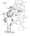
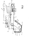
- the weighing device essentially consists of a weighing container 1, a weighing control 2, a collecting device 3, a metering belt 4 and a preliminary container 5, the weighing container 1 being shown only very schematically in the figure. It is held on its left side by a four-bar support 6, through which the horizontal force component occurring here is absorbed. Right on the scale container 1 a load cell 7 is attached, which detects the vertical force component, in particular the weight of the scale container 1, and reports it to the scale control via a corresponding line 8.
- the scale container 1 has a bottom slide 9, which can be actuated by the scale control 2 via a pneumatic cylinder 10. Under the scales container 1 is a bag 11 is shown, which is intended to symbolize an automatic A bsack- device.
- the collecting device 3 is formed by two separate units, namely a fine flow collecting device 12 and a coarse flow collecting container 13.
- the coarse flow collecting container 13 has a shut-off device 14 with an electro-pneumatic valve 15 and a pneumatic cylinder 16. Accordingly, the fine flow collecting device is equipped with a shut-off device 17 as well as an electropneumatic valve 18 and a pneumatic cylinder 19.
- a collecting funnel 20 has two adjustable flaps 21 and 21 'which (as indicated by arrows 22') about axes 22 'in an opening or closing direction :. can be moved in the sense that a corresponding change in the ratio of zones A and B occurs.
- the relative size of the two zones is usually only set once during commissioning, after which an undesired adjustment by the assembly personnel (by means not shown here) is prevented.
- Z FIG. 3 shows a scraper 30 and the corresponding mechanical structure of the metering device on a larger scale.
- the scraper 30 is set by an electromotive drive 31: two commercially available rotary capacitors 32 and 33 allow precisely reproducible settings by electrical adjustment via a remote control device 34. What is essential here is the absolute dimension "X" of the layer thickness, which is primarily intended to compensate for the variations in the bulk density of the product.
- FIG. 3 also shows a geared motor 35, each with a winding 36 or 37 for a low or a high speed. A steplessly adjustable motor could also be provided for the same purpose.
- the combination of mechanical and electronic control means described has proven to be particularly advantageous in the device shown.
- the weighing cycle can be defined by the scale controller 2 (as a time cycle: coarse flow metering / fine flow metering / calming phase for the scale) and in the assignment of high to low belt speed.
- both the scale controller 2 and the remote control device 34 can be connected to a central computer 40, which is based on the preprogrammed scale controller and corresponding empirical values to be recorded for the setting of the scraper 30 and controls the other system elements accordingly.
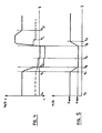
- the time t 0 is chosen arbitrarily in the weighing cycle.
- the belt speed is reduced from the value V large to V small . Accordingly, the two metering capacities (namely main and fine metering flow) are reduced, for example to a third of the full capacity.
- the shut-off device 14 is closed.
- the corresponding product output of the coarse flow metering is now temporarily stored in the main metering stream collecting container 13 until time t 4 . From time t 2 to time t 3 , only the fine flow metering works, also here because of the reduced belt speed with very low power.
- the target weight is reached and the shut-off device 17 for the fine metering flow also closes.
- the product performance of the fine flow metering is also temporarily stored in the fine flow collecting device 12 from now until time t 4 .
- the two shut-off devices 14 and 17 are opened again and the belt speed is increased again to its large value.
- the product feed into the scales container reaches a maximum again at the start of a new weighing cycle, since the temporarily stored bulk quantity is added to the full transport capacity of the belt, for example at time t 5 (when the belt speed has increased again from V small to V large ) Scale container is drained with. By locking or switching off the scale mechanism, a disruptive influence on the sensitive parts of the scale can be avoided.
- the fine flow metering and at time t 7 the main flow metering resumes at normal performance level.
- FIG. 4 and FIG. 5 are ideal, very simplified representations, in which, for example, the overshoots in the event of pulse changes on the supply side or the like. are not shown.
Landscapes
- Physics & Mathematics (AREA)
- General Physics & Mathematics (AREA)
- Weight Measurement For Supplying Or Discharging Of Specified Amounts Of Material (AREA)
Priority Applications (1)
| Application Number | Priority Date | Filing Date | Title |
|---|---|---|---|
| PCT/EP1983/000127 WO1983004306A1 (fr) | 1982-05-21 | 1983-05-20 | Procede pour peser de la matiere en vrac et dispositif de pesee |
Applications Claiming Priority (4)
| Application Number | Priority Date | Filing Date | Title |
|---|---|---|---|
| CH314982 | 1982-05-21 | ||
| CH3149/82 | 1982-05-21 | ||
| DE3244338 | 1982-11-30 | ||
| DE19823244338 DE3244338A1 (de) | 1982-05-21 | 1982-11-30 | Verfahren zum verwaegen von schuettgut und verwaegevorrichtung |
Publications (1)
| Publication Number | Publication Date |
|---|---|
| EP0095095A1 true EP0095095A1 (fr) | 1983-11-30 |
Family
ID=25692313
Family Applications (1)
| Application Number | Title | Priority Date | Filing Date |
|---|---|---|---|
| EP83104677A Withdrawn EP0095095A1 (fr) | 1982-05-21 | 1983-05-11 | Procédé par le pesage de matière en vrac et dispositif de pesage |
Country Status (2)
| Country | Link |
|---|---|
| EP (1) | EP0095095A1 (fr) |
| JP (1) | JPS59500985A (fr) |
Cited By (10)
| Publication number | Priority date | Publication date | Assignee | Title |
|---|---|---|---|---|
| EP0144497A1 (fr) * | 1983-12-13 | 1985-06-19 | Automatic Mechanical System Engineering Company | Balance pour peser des produits en vrac |
| EP0348592A3 (fr) * | 1988-07-01 | 1991-03-06 | Greif-Werk Maschinenfabrik GmbH | Procédé et balance pour le pesage en portions de matériaux en vrac |
| GB2266598A (en) * | 1992-04-18 | 1993-11-03 | Truetzschler Gmbh & Co Kg | Apparatus and method for feeding and weighing textile fibres |
| EP0618429A1 (fr) * | 1993-04-02 | 1994-10-05 | Compagnie Generale Des Etablissements Michelin-Michelin & Cie | Procédé et dispositif de dosage, en particulier pour matières conditionnées en poudre |
| EP0621467A1 (fr) * | 1993-04-23 | 1994-10-26 | LICO SpA. | Dispositif de dosage en continu |
| GB2335915A (en) * | 1998-04-01 | 1999-10-06 | Transmatic Fyllan Limited | Conveying flowable materials |
| CN105043514A (zh) * | 2015-08-14 | 2015-11-11 | 苏州隆士丹自动化技术有限公司 | 一种自动称重机 |
| CN106429213A (zh) * | 2016-09-22 | 2017-02-22 | 盐城工学院 | 一种物料输送机构 |
| CN113008343A (zh) * | 2021-02-25 | 2021-06-22 | 广东韶钢松山股份有限公司 | 密闭型电子皮带秤 |
| CN120063454A (zh) * | 2025-04-27 | 2025-05-30 | 常州均先机械有限公司 | 一种物料静态称重装置 |
Families Citing this family (2)
| Publication number | Priority date | Publication date | Assignee | Title |
|---|---|---|---|---|
| CN104229436A (zh) * | 2014-08-22 | 2014-12-24 | 北方重工集团有限公司 | 一种定量给料调节装置 |
| CN107539506A (zh) * | 2017-08-04 | 2018-01-05 | 安徽省新旭堂茶业有限公司 | 一种茶叶包装机 |
Citations (6)
| Publication number | Priority date | Publication date | Assignee | Title |
|---|---|---|---|---|
| DE580802C (de) * | 1928-05-22 | 1933-07-21 | Fr Hesser Maschinenfabrik A G | Elektrisch gesteuerte Waegevorrichtung |
| DE1274807B (de) * | 1964-08-14 | 1968-08-08 | Reuther & Reisert Chronos Werk | Grob-Feinstromzufuehrung zu einer selbsttaetigen Waage |
| DE1291526B (de) * | 1965-01-15 | 1969-03-27 | Reuther & Reisert Chronos Werk | Selbsttaetige Abwaegevorrichtung |
| DE1774348A1 (de) * | 1968-05-29 | 1972-01-13 | Dynamit Nobel Ag | Verfahren zum selbsttaetigen Dosieren von fliessfaehigen Stoffen und Dosierwaage zur Durchfuehrung dieses Verfahrens |
| US3700054A (en) * | 1971-09-13 | 1972-10-24 | Stanley A Mcclusky | Two station receptacle and weighing apparatus |
| US4010809A (en) * | 1973-07-17 | 1977-03-08 | Hobart Engineering Limited | Weighing method |
-
1983
- 1983-05-11 EP EP83104677A patent/EP0095095A1/fr not_active Withdrawn
- 1983-05-20 JP JP58501721A patent/JPS59500985A/ja active Pending
Patent Citations (6)
| Publication number | Priority date | Publication date | Assignee | Title |
|---|---|---|---|---|
| DE580802C (de) * | 1928-05-22 | 1933-07-21 | Fr Hesser Maschinenfabrik A G | Elektrisch gesteuerte Waegevorrichtung |
| DE1274807B (de) * | 1964-08-14 | 1968-08-08 | Reuther & Reisert Chronos Werk | Grob-Feinstromzufuehrung zu einer selbsttaetigen Waage |
| DE1291526B (de) * | 1965-01-15 | 1969-03-27 | Reuther & Reisert Chronos Werk | Selbsttaetige Abwaegevorrichtung |
| DE1774348A1 (de) * | 1968-05-29 | 1972-01-13 | Dynamit Nobel Ag | Verfahren zum selbsttaetigen Dosieren von fliessfaehigen Stoffen und Dosierwaage zur Durchfuehrung dieses Verfahrens |
| US3700054A (en) * | 1971-09-13 | 1972-10-24 | Stanley A Mcclusky | Two station receptacle and weighing apparatus |
| US4010809A (en) * | 1973-07-17 | 1977-03-08 | Hobart Engineering Limited | Weighing method |
Cited By (11)
| Publication number | Priority date | Publication date | Assignee | Title |
|---|---|---|---|---|
| EP0144497A1 (fr) * | 1983-12-13 | 1985-06-19 | Automatic Mechanical System Engineering Company | Balance pour peser des produits en vrac |
| EP0348592A3 (fr) * | 1988-07-01 | 1991-03-06 | Greif-Werk Maschinenfabrik GmbH | Procédé et balance pour le pesage en portions de matériaux en vrac |
| GB2266598A (en) * | 1992-04-18 | 1993-11-03 | Truetzschler Gmbh & Co Kg | Apparatus and method for feeding and weighing textile fibres |
| EP0618429A1 (fr) * | 1993-04-02 | 1994-10-05 | Compagnie Generale Des Etablissements Michelin-Michelin & Cie | Procédé et dispositif de dosage, en particulier pour matières conditionnées en poudre |
| US5938074A (en) * | 1993-04-02 | 1999-08-17 | Compagnie Generale Des Etablissments Michelin - Michelin & Cie | Metering method and metering device for powder materials |
| EP0621467A1 (fr) * | 1993-04-23 | 1994-10-26 | LICO SpA. | Dispositif de dosage en continu |
| GB2335915A (en) * | 1998-04-01 | 1999-10-06 | Transmatic Fyllan Limited | Conveying flowable materials |
| CN105043514A (zh) * | 2015-08-14 | 2015-11-11 | 苏州隆士丹自动化技术有限公司 | 一种自动称重机 |
| CN106429213A (zh) * | 2016-09-22 | 2017-02-22 | 盐城工学院 | 一种物料输送机构 |
| CN113008343A (zh) * | 2021-02-25 | 2021-06-22 | 广东韶钢松山股份有限公司 | 密闭型电子皮带秤 |
| CN120063454A (zh) * | 2025-04-27 | 2025-05-30 | 常州均先机械有限公司 | 一种物料静态称重装置 |
Also Published As
| Publication number | Publication date |
|---|---|
| JPS59500985A (ja) | 1984-05-31 |
Similar Documents
| Publication | Publication Date | Title |
|---|---|---|
| DE102007050268B4 (de) | Vorrichtung zum dosierten Mischen von schüttbaren Materialkomponenten sowie Kunststoffverarbeitungsmaschine | |
| DE69626731T2 (de) | Körnchenbarriere und Körnchenwägeapparat damit | |
| DE2807068A1 (de) | Mischanlage, insbesondere zur herstellung von beton | |
| EP0095095A1 (fr) | Procédé par le pesage de matière en vrac et dispositif de pesage | |
| DE1558551A1 (fr) | ||
| DE3309744C2 (fr) | ||
| DE3708078C2 (fr) | ||
| DE3208019C2 (de) | Vorrichtung zum Wiegen von Früchten und zum Zusammenstellen einer Menge aus diesen Früchten | |
| WO1983004306A1 (fr) | Procede pour peser de la matiere en vrac et dispositif de pesee | |
| DE3635138C2 (fr) | ||
| WO2000034557A1 (fr) | Melange de composants fibreux | |
| DE19756367C2 (de) | Fütterungsanlage für die Tierhaltung | |
| DE19518298C2 (de) | Verfahren zum Sortieren von Stückgütern | |
| DE2912937C2 (de) | Verfahren und Anlage zum Bilden von einem Mischer zuzuführenden Kautschukchargen | |
| EP0599047B1 (fr) | Procédé pour déterminer le débit de matière retirée par une extrudeuse d'une trémie d'alimentation | |
| DD251623A1 (de) | Verfahren und vorrichtung zur kontinuierlichen glaettung eines gutstromes von rieselfaehigem, pulverfoermigem bis koernigem gut | |
| EP0230483A1 (fr) | Procédé pour uniformiser des particules de dispersion et machine pour exécuter ce procédé | |
| EP0273254B1 (fr) | Procédé et dispositif pour remplir des matières en vrac, spécialement du café | |
| DE2506016B2 (de) | Verfahren und vorrichtung zum aufgeben von gruenpellets auf den wanderrost eines vorbehandlungsofens | |
| DE3244338A1 (de) | Verfahren zum verwaegen von schuettgut und verwaegevorrichtung | |
| DE2849900C2 (fr) | ||
| EP0945716B1 (fr) | Dispositif de pesage combinatoire | |
| DE1101785B (de) | Einrichtung zum Zufuehren eines kontinuierlich zugeteilten Schuettgutgemenges an einen intermittierend zu beschickenden Verbraucher | |
| EP3971115A1 (fr) | Unité de bande de séparation, ainsi que son procédé de fonctionnement | |
| DE1507887A1 (de) | Verfahren und Vorrichtung zum Herstellen eines bestimmten Mischungsverhaeltnisses verschiedener Komponenten |
Legal Events
| Date | Code | Title | Description |
|---|---|---|---|
| PUAI | Public reference made under article 153(3) epc to a published international application that has entered the european phase |
Free format text: ORIGINAL CODE: 0009012 |
|
| AK | Designated contracting states |
Designated state(s): FR GB IT NL |
|
| 17P | Request for examination filed |
Effective date: 19831031 |
|
| STAA | Information on the status of an ep patent application or granted ep patent |
Free format text: STATUS: THE APPLICATION HAS BEEN WITHDRAWN |
|
| 18W | Application withdrawn |
Withdrawal date: 19850621 |
|
| RIN1 | Information on inventor provided before grant (corrected) |
Inventor name: GMUER, BRUNO |