EP0095108A2 - Dispositif pour fermer et ouvrir simultanément un groupe de stores - Google Patents
Dispositif pour fermer et ouvrir simultanément un groupe de stores Download PDFInfo
- Publication number
- EP0095108A2 EP0095108A2 EP83104731A EP83104731A EP0095108A2 EP 0095108 A2 EP0095108 A2 EP 0095108A2 EP 83104731 A EP83104731 A EP 83104731A EP 83104731 A EP83104731 A EP 83104731A EP 0095108 A2 EP0095108 A2 EP 0095108A2
- Authority
- EP
- European Patent Office
- Prior art keywords
- slats
- blinds
- drive means
- axis
- group
- Prior art date
- Legal status (The legal status is an assumption and is not a legal conclusion. Google has not performed a legal analysis and makes no representation as to the accuracy of the status listed.)
- Granted
Links
Images


Classifications
-
- E—FIXED CONSTRUCTIONS
- E06—DOORS, WINDOWS, SHUTTERS, OR ROLLER BLINDS IN GENERAL; LADDERS
- E06B—FIXED OR MOVABLE CLOSURES FOR OPENINGS IN BUILDINGS, VEHICLES, FENCES OR LIKE ENCLOSURES IN GENERAL, e.g. DOORS, WINDOWS, BLINDS, GATES
- E06B9/00—Screening or protective devices for wall or similar openings, with or without operating or securing mechanisms; Closures of similar construction
- E06B9/24—Screens or other constructions affording protection against light, especially against sunshine; Similar screens for privacy or appearance; Slat blinds
- E06B9/26—Lamellar or like blinds, e.g. venetian blinds
- E06B9/28—Lamellar or like blinds, e.g. venetian blinds with horizontal lamellae, e.g. non-liftable
- E06B9/30—Lamellar or like blinds, e.g. venetian blinds with horizontal lamellae, e.g. non-liftable liftable
- E06B9/32—Operating, guiding, or securing devices therefor
-
- Y—GENERAL TAGGING OF NEW TECHNOLOGICAL DEVELOPMENTS; GENERAL TAGGING OF CROSS-SECTIONAL TECHNOLOGIES SPANNING OVER SEVERAL SECTIONS OF THE IPC; TECHNICAL SUBJECTS COVERED BY FORMER USPC CROSS-REFERENCE ART COLLECTIONS [XRACs] AND DIGESTS
- Y10—TECHNICAL SUBJECTS COVERED BY FORMER USPC
- Y10S—TECHNICAL SUBJECTS COVERED BY FORMER USPC CROSS-REFERENCE ART COLLECTIONS [XRACs] AND DIGESTS
- Y10S160/00—Flexible or portable closure, partition, or panel
- Y10S160/17—Venetian blinds, motor driven
Definitions
- the present invention relates to blinds for fitting inside double or . triple glass windows or, if the windows are hermetically sealed, inside the windows.
- a conventional blind has two functions, namely as sun shelter and for hindering insight through the window.
- a so called heat insulating blind has been constructed, which besides above mentioned functions also acts as an effective heat insulator in its closed position.
- Such a heat insulating blind is for instance described in Swedish Patent No. 400 601.
- blinds are usually operated by a hand-operated mechanism, and in order to obtain a simple blind construction the slats are by means of vertical cords suspended from a horizontal axis of rotation arranged above the slats, for instance as shown in above mentioned patent. It is also previously known to operate the turning of the slats and also their lowering and lifting by means of a motor provided with a gear box. This comparatively complicated drive mechanism can also be provided with a sliding clutch that slides in case of a faulty operation or other trouble in order not to damage the slats. Moreover, it is previously known to operate simultaneously several blinds arranged in a straight row by means of a common rotation shaft for these blinds.
- the object of the present invention is to be able by means of constructively simple and small driving means adapted to required torque for opening and closing the slats in each blind to simultaneously at determined points of time set the slats in a group of individually . hand-operated blinds in a closed or open position irrespectively of the existing position of the slats in each blind and without risk for damage on said drive means.
- the invention relates to an apparatus for simultaneously closing and opening a group of blinds each consisting of a number of thin slats, which are by means of vertical cords suspended from at least one horizontal axis of rotation arranged above the slats and upon rotation of said axis via the vertical cords turnably adjustable between a substantially horizontal open position and a substantially vertical closed position, said axis being connected to a hand-operated mechanism for individual adjustment of the slats in each blind, and the invention is characterized in driving means connected to said axis of each blind, said driving means being provided with means for limiting the torque excerted on said driving means upon the turning movement of the slats, and a timing device connected to all said driving means in the group of blinds for automatic actuation of said driving means at determined points of time and setting of the slats in all blinds in the group to closed or open position irrespective of their existing position set by said hand-operated mechanism.
- the present invention is a combination of blinds having hand-operated mechanisms and simultaneously operated automatic drive means. From a fully closed or open position the slats in all blinds can also by means of said drive means be adjusted to the same intermediate position by applying the necessary power for said drive means an adapted time for reaching said intermediate position. Moreover, the slats of each blind can also be manually adjusted to any positioning as required by the existing wheather conditions and individual request. The torque excerted on said drive means upon manual operation can be considerably higher than the required torque for just opening and closing the slats by said drive means.
- said drive means shall be constructively simple and adapted to said required torque
- said torque limiting means is arranged for protecting said drive means from being damaged as a result of the comparatively higher torque during manual operation. Since furthermore each blind in the group is provided with an axis of rotation, a hand-operated mechanism and drive means, there is no limitation as to an arrangement in straight rows nor concerning the number of blinds in the group.
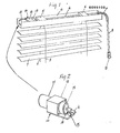
- the blinds consist of thin slats 1 attached to the vertical cords 2 and 3, which are attached to a horizontal rotation shaft 4 journalled in bearings 5 arranged in a channel 6 above the slats.
- one end of the rotation shaft 4 is via a flexible shaft 7 and a bar 8 connected to a hand-operated mechanism 9 for manual rotation of the shaft 4 and thereby a turning movement of the slats 1 via the cords 2,3.
- the other end of the shaft 4 is directly connected to a drive unit 10 arranged in the channel 5.
- the drive unit consists of an electric motor 11, a gear box 12 and a sliding clutch 13.
- the rotation of the shaft 4 upon the actuation of the drive unit 10 is limited by cooperation between a pin 14 fixed to the shaft 4 and a fixed stop 15.
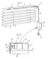
- the embodiment shown in Fig. 3 differs from the embodiment of Fig. 1 particularly in that the drive unit, here designated with the reference numeral 16, is connected to the bar 8 between the flexible shaft 7 and the hand-operated mechanism 9.
- the drive unit 16 is enclosed in a casing 17 and, as shown in Fig. 3, consists also in this embodiment of an electric motor 11, a gear box 12 and a sliding clutch 13.
- the output shaft 18 from the clutch 12 is provided with a gear 19 in engagement with a gear 20 on the bar 8.
- the rotation of the bar 8 is limited by cooperation between a pin 21 fixed to the output shaft 18 and a stop 22 attached to the casing 17.
- the required torque for opening and closing the slats in blinds of the kind schematically shown on the drawings is about 4000 gram mm.
- This torque can be obtained by means of a small electric motor 11 and gear box 12.
- the torque obtained upon manual adjustment of the slats can easily exceed 8000 gram mm. This is a considerably larger torque than permitted for the gear box. If, accordingly, the motor and gear box should be directly coupled to the rotation shaft 4, there is an obvious risk for damaging the gear box when the slats are adjusted by the hand-operated mechanism 9. This risk is eliminated by the sliding clutch 13, which limits the torque.
- Fig. 5 illustrates schematically the simultaneous automatic operation of a group of blinds, here exemplified three blinds.
- the drive units 9 or 16 are by electric cables 32 via a hand switch 33 connected to a central control box 34, which includes a timer controlled switch 35 and a transformer 36.
- the setting of the slats in the separate blinds can be unknown depending on the fact, that the blinds can have been controlled individually and the slats accordingly been set in different positions. It is presumed, that the blinds are in fully open positioned and that accordingly maximum possible turning of the slats is required for closing them. Automatic closing is obtained by supplying voltage to the motors 11 during sufficient long time for ensuring a full closing from a fully open position. In cases when a blind is not fully open, the slats reach the fully closed position prior to the motor is shut off. Thus, the motor runs even when the blind is fully closed. However, the gear box 12 is prevented from being damaged by the fact that the sliding clutch starts to func- .tion.
- the above described torque limiting unit in the form of a sliding clutch 13 protects gear box 12 when hand mechanism 9 is used, protects gearbox when stop position is reached (fully closed on open position) and motor still runs and also allows motor to run when stop position is reached.
- the opening of the blinds normally takes place in the morning. In most cases the blinds have not been manually adjusted during the night. When the blinds are opened, they will start from the same fully closed position and the actuation of all motors 11 at the same determined point of time ensures that all blinds will be opened to the same angle. The blinds can then be individually adjusted to desired positions by the hand-operated mechanism 9.
- FIG. 6 and 7 Another embodiment of a torque limiting unit is shown in Figs. 6 and 7.
- This unit generally designated with the reference numeral 23, consists of a cylindrical cam unit, one end of which consists of a bar 24 and the other end consits of a hollow tube 25.
- the output shaft 26 from the gear box 12 is threaded into the bar 12 and the blind rotating shaft 4 is rotatably journalled in the tube 25.
- a recess is cut-out in the tube 25 for providing two opposite guide surfaces 27 and 27a. These surfaces cooperate with a pin 28 fixed to the shaft 4.
- the cam unit 23 is prevented from rotation by a guide ledge 29 extending in the direction of the shaft 4 but allowed to move along the ledge between two fixed stops 30 and 31.
- the gear box 12 Upon actuation of the electric motor 11 the gear box 12 rotates the threaded output shaft 26 causing the cam unit 23 to move along the ledge 29.
- the direction of movement depends on the direction of the rotation of the shaft 26 and the movement in either direction is caused by the simple procedure of reversing the voltage supplied to the electric motor.
- the movement results in either guide surfaces 27, 27a coming into contact with the pin 28, and the cooperation between pin and guide surface causes the shaft 4 to rotate and so opening or closing the slats 1.
- the stops 30 and 31 denote that the slats have reached the fully open or fully closed position.
- the cam unit may have an effective reduction ratio of 20:1, i.e. the threaded shaft 26 rotates twenty times for one rotation of the shaft 4 (in practice the shaft 4 only completes a part of one revolution). This means, that when the cam unit reaches a stop 30 or 31, the maximum torque excerted on the gear box 12 is limited to the stall torque of the motor 11 multiplied by the reduction ratio of the gear box, which can be approx. 25:1. This the gear box can well be designed to tolerate.
- the cam unit 23 also ensures that when the hand-operated mechanism 9 is operated at the same time as the blind is being operated by the motor, the large torque from the hand-operation is not transmitted directly to the gear box 12 causing it to be damaged. Moreover, the cam unit can be returned to a central neutral position after each operation, in which neutral position the pin 28 is not in contact with either guide surface 27, 27a. In this position hand operation can occur without the pin contacting a guide surface and consequently without transmitting any torque to the gear box.
Landscapes
- Engineering & Computer Science (AREA)
- Structural Engineering (AREA)
- Architecture (AREA)
- Civil Engineering (AREA)
- Blinds (AREA)
- Specific Sealing Or Ventilating Devices For Doors And Windows (AREA)
- Wing Frames And Configurations (AREA)
Priority Applications (1)
| Application Number | Priority Date | Filing Date | Title |
|---|---|---|---|
| AT83104731T ATE27986T1 (de) | 1982-05-21 | 1983-05-13 | Vorrichtung zum gleichzeitigen schliessen und oeffnen einer gruppe von vorhaengen. |
Applications Claiming Priority (2)
| Application Number | Priority Date | Filing Date | Title |
|---|---|---|---|
| SE8203173 | 1982-05-20 | ||
| SE8203173A SE450143B (sv) | 1982-05-21 | 1982-05-21 | Anordning for samtidigt oppnande och stengande av grupp av persienner |
Publications (3)
| Publication Number | Publication Date |
|---|---|
| EP0095108A2 true EP0095108A2 (fr) | 1983-11-30 |
| EP0095108A3 EP0095108A3 (en) | 1984-02-22 |
| EP0095108B1 EP0095108B1 (fr) | 1987-06-24 |
Family
ID=20346865
Family Applications (1)
| Application Number | Title | Priority Date | Filing Date |
|---|---|---|---|
| EP83104731A Expired EP0095108B1 (fr) | 1982-05-21 | 1983-05-13 | Dispositif pour fermer et ouvrir simultanément un groupe de stores |
Country Status (6)
| Country | Link |
|---|---|
| US (1) | US4550759A (fr) |
| EP (1) | EP0095108B1 (fr) |
| AT (1) | ATE27986T1 (fr) |
| CA (1) | CA1232192A (fr) |
| DE (1) | DE3372225D1 (fr) |
| SE (1) | SE450143B (fr) |
Cited By (12)
| Publication number | Priority date | Publication date | Assignee | Title |
|---|---|---|---|---|
| EP0702855A4 (fr) * | 1993-06-11 | 1996-09-04 | Harmonic Design Inc | Actionneur pour store a mini-lamelles |
| US5698958A (en) * | 1993-06-11 | 1997-12-16 | Harmonic Design, Inc. | Head rail-mounted actuator for window coverings |
| US5729103A (en) * | 1993-06-11 | 1998-03-17 | Harmonic Design, Inc. | Head rail-mounted actuator for window coverings |
| DE19755922A1 (de) * | 1997-12-17 | 1999-06-24 | Geiger Gerhard Gmbh & Co | Antriebseinheit für Jalousien |
| US5990646A (en) * | 1996-09-06 | 1999-11-23 | Hunter Douglas Inc. | Remotely-controlled battery powered-window covering having power saving receiver |
| US6060852A (en) * | 1993-06-11 | 2000-05-09 | Harmonic Design, Inc. | Head rail-mounted actuator for window covering |
| FR2931262A1 (fr) * | 2008-05-15 | 2009-11-20 | Somfy Sas | Procede de commande groupee d'ecrans motorises, automatisme pour la mise en oeuvre de ce procede et installations domotiques comprenant un tel automatisme |
| EP2602422A1 (fr) * | 2011-12-07 | 2013-06-12 | Shih-Ming Lin | Dispositif de rotation d'un rouleau d'enroulement d'un store de fenêtre |
| KR101274661B1 (ko) * | 2008-09-18 | 2013-06-17 | 시티에스 코포레이션 | 덮개 필터를 구비한 rf 모노블록 필터 조립체 |
| WO2016078674A1 (fr) * | 2014-11-18 | 2016-05-26 | Jalousier Oü | Dispositif et procédé de commande et d'automatisation de store |
| EP3312374A1 (fr) * | 2016-10-19 | 2018-04-25 | Hunter Douglas Inc. | Couverture de structure architecturale à double mode |
| US10547190B2 (en) * | 2017-05-05 | 2020-01-28 | Hall Labs Llc | Rechargeable powered covering for a architectural opening |
Families Citing this family (24)
| Publication number | Priority date | Publication date | Assignee | Title |
|---|---|---|---|---|
| FR2572767B1 (fr) * | 1984-11-05 | 1988-04-08 | Nergeco Sa | Dispositif de fixation et de protection de l'element moteur des portes accordeon |
| DK158054C (da) * | 1985-01-10 | 1990-08-20 | Rasmussen Kann Ind As | Elektrisk drivarrangement for persienne |
| US4712104A (en) * | 1985-04-19 | 1987-12-08 | Kuron Kabushiki Kaisha | Remote control blind system |
| SE8603948L (sv) * | 1986-09-19 | 1988-03-20 | Ambient Energy Design | Anordning for lyftning och senkning av lameller i en persienn |
| US4979550A (en) * | 1989-04-25 | 1990-12-25 | Long Richard G | Window blind control apparatus |
| US5133399A (en) * | 1990-12-17 | 1992-07-28 | Hiller Jeffrey H | Apparatus by which horizontal and vertical blinds, pleated shades, drapes and the like may be balanced for "no load" operation |
| US5495153A (en) * | 1993-06-11 | 1996-02-27 | Harmonic Design, Inc. | Head rail-mounted mini-blind actuator for vertical blinds and pleated shades |
| US5517094A (en) * | 1993-07-20 | 1996-05-14 | Harmonic Design, Inc. | Head rail-mounted mini-blind actuator |
| US5413161A (en) * | 1993-09-09 | 1995-05-09 | Corazzini; Warren | Solar powered window shade |
| US5465779A (en) * | 1994-07-22 | 1995-11-14 | Rozon; David | Integrated cord loop drive means and housing for window covering |
| US5818183A (en) * | 1994-12-06 | 1998-10-06 | Auto-Tilt Enterprises, Ltd. | Blind tilt controller |
| US5547008A (en) * | 1995-02-02 | 1996-08-20 | Sullivan; Kenneth J. | Mini blind and vertical blind actuator |
| US5603371A (en) * | 1995-06-05 | 1997-02-18 | Gregg; Richard D. | Electronic power angling rod for a window blind |
| US5760558A (en) * | 1995-07-24 | 1998-06-02 | Popat; Pradeep P. | Solar-powered, wireless, retrofittable, automatic controller for venetian blinds and similar window converings |
| US6388404B1 (en) | 1996-01-03 | 2002-05-14 | Decotex 2000 Corporation | Remote controlled window treatment and/or lighting system |
| US5645685A (en) * | 1996-01-05 | 1997-07-08 | Furhman; Thomas C. | Venetian blinds |
| FR2761108B1 (fr) * | 1997-03-21 | 1999-05-28 | Somfy | Bloc baie equipe d'un produit d'occultation motorise |
| US6470951B1 (en) * | 2000-11-20 | 2002-10-29 | Hsiu-Chih Tao | Structure of a blind adjustment |
| US20040163774A1 (en) * | 2002-03-07 | 2004-08-26 | Ming Nien | Venetian blind having dual-drive mechanism |
| US20030188836A1 (en) * | 2002-04-05 | 2003-10-09 | Greg Whiting | Automated venetian blinds |
| US20050189078A1 (en) * | 2002-04-05 | 2005-09-01 | Greg Whiting | Automated venetian blinds |
| US20070144683A1 (en) * | 2005-12-27 | 2007-06-28 | Krochmal Andrew R | Door glass assembly with powered blind |
| US20090242145A1 (en) * | 2008-03-30 | 2009-10-01 | Sheu Jia Yih | Motorized shade assembly with reduced vibration and noise |
| US8981681B2 (en) * | 2011-01-28 | 2015-03-17 | Gholamali Malekpour | Motorized blind control devices, methods of use thereof |
Family Cites Families (8)
| Publication number | Priority date | Publication date | Assignee | Title |
|---|---|---|---|---|
| US1830405A (en) * | 1927-01-12 | 1931-11-03 | Ohno Tadashi | Shutter |
| US2709220A (en) * | 1954-01-25 | 1955-05-24 | Nat Electronic Mfg Corp | Extensible and retractible antenna |
| US3249148A (en) * | 1962-06-26 | 1966-05-03 | Ronald J Zablodil | Automatic venetian blinds |
| BE755183R (fr) * | 1969-08-28 | 1971-02-01 | Hueppe Justin | Dispositif de controle pour installation pare-soleil actionnee par un moteur |
| US3646985A (en) * | 1970-04-13 | 1972-03-07 | Justin Huppe Kg | Venetian blind with automatic control of room brightness |
| DE2153494A1 (de) * | 1971-10-27 | 1973-05-03 | Leonhard Holzberger | Automatische rolladenwinde fuer verschiedene anwendungsmoeglichkeiten |
| US4096903A (en) * | 1974-07-05 | 1978-06-27 | Ringle Iii John | Power drive for a venetian blind |
| US4173721A (en) * | 1978-03-17 | 1979-11-06 | Louis Emma D | Window shade controls and method associated therewith |
-
1982
- 1982-05-21 SE SE8203173A patent/SE450143B/sv unknown
-
1983
- 1983-05-13 AT AT83104731T patent/ATE27986T1/de active
- 1983-05-13 EP EP83104731A patent/EP0095108B1/fr not_active Expired
- 1983-05-13 DE DE8383104731T patent/DE3372225D1/de not_active Expired
- 1983-05-16 US US06/495,276 patent/US4550759A/en not_active Expired - Fee Related
- 1983-05-20 CA CA000428569A patent/CA1232192A/fr not_active Expired
Cited By (20)
| Publication number | Priority date | Publication date | Assignee | Title |
|---|---|---|---|---|
| EP0702855A4 (fr) * | 1993-06-11 | 1996-09-04 | Harmonic Design Inc | Actionneur pour store a mini-lamelles |
| US5698958A (en) * | 1993-06-11 | 1997-12-16 | Harmonic Design, Inc. | Head rail-mounted actuator for window coverings |
| US5714855A (en) * | 1993-06-11 | 1998-02-03 | Harmonic Design, Inc. | Head rail-mounted actuator for window coverings |
| US5729103A (en) * | 1993-06-11 | 1998-03-17 | Harmonic Design, Inc. | Head rail-mounted actuator for window coverings |
| US5907227A (en) * | 1993-06-11 | 1999-05-25 | Harmonic Design, Inc. | Head rail-mounted actuator for window coverings |
| US6060852A (en) * | 1993-06-11 | 2000-05-09 | Harmonic Design, Inc. | Head rail-mounted actuator for window covering |
| US5883480A (en) * | 1995-11-15 | 1999-03-16 | Harmonic Desing, Inc. | Window covering with head rail-mounted actuator |
| US5990646A (en) * | 1996-09-06 | 1999-11-23 | Hunter Douglas Inc. | Remotely-controlled battery powered-window covering having power saving receiver |
| DE19755922A1 (de) * | 1997-12-17 | 1999-06-24 | Geiger Gerhard Gmbh & Co | Antriebseinheit für Jalousien |
| WO2009150345A3 (fr) * | 2008-05-15 | 2010-03-04 | Somfy Sas | Procede de commande groupee d'ecrans motorises, automatisme pour la mise en oeuvre de ce procede et installations domotiques comprenant un tel automatisme |
| FR2931262A1 (fr) * | 2008-05-15 | 2009-11-20 | Somfy Sas | Procede de commande groupee d'ecrans motorises, automatisme pour la mise en oeuvre de ce procede et installations domotiques comprenant un tel automatisme |
| US8393378B2 (en) | 2008-05-15 | 2013-03-12 | Somfy Sas | Group control method for controlling motor-driven screens as a group, automatic motor control for implementing the method, and home automation installations including such automatic motor control |
| CN102027425B (zh) * | 2008-05-15 | 2013-06-12 | Somfy公司 | 机动幕帘的分组控制方法 |
| KR101274661B1 (ko) * | 2008-09-18 | 2013-06-17 | 시티에스 코포레이션 | 덮개 필터를 구비한 rf 모노블록 필터 조립체 |
| EP2602422A1 (fr) * | 2011-12-07 | 2013-06-12 | Shih-Ming Lin | Dispositif de rotation d'un rouleau d'enroulement d'un store de fenêtre |
| WO2016078674A1 (fr) * | 2014-11-18 | 2016-05-26 | Jalousier Oü | Dispositif et procédé de commande et d'automatisation de store |
| EP3312374A1 (fr) * | 2016-10-19 | 2018-04-25 | Hunter Douglas Inc. | Couverture de structure architecturale à double mode |
| US10655384B2 (en) | 2016-10-19 | 2020-05-19 | Hunter Douglas, Inc. | Dual mode architectural structure covering |
| AU2017248421B2 (en) * | 2016-10-19 | 2023-05-25 | Hunter Douglas Inc. | Dual mode architectural structure covering |
| US10547190B2 (en) * | 2017-05-05 | 2020-01-28 | Hall Labs Llc | Rechargeable powered covering for a architectural opening |
Also Published As
| Publication number | Publication date |
|---|---|
| DE3372225D1 (en) | 1987-07-30 |
| SE8203173L (sv) | 1983-11-22 |
| ATE27986T1 (de) | 1987-07-15 |
| EP0095108B1 (fr) | 1987-06-24 |
| EP0095108A3 (en) | 1984-02-22 |
| US4550759A (en) | 1985-11-05 |
| CA1232192A (fr) | 1988-02-02 |
| SE450143B (sv) | 1987-06-09 |
Similar Documents
| Publication | Publication Date | Title |
|---|---|---|
| EP0095108B1 (fr) | Dispositif pour fermer et ouvrir simultanément un groupe de stores | |
| US5547008A (en) | Mini blind and vertical blind actuator | |
| US4096903A (en) | Power drive for a venetian blind | |
| US5889377A (en) | Drapery actuator | |
| DE3801560C2 (fr) | ||
| HUT40714A (en) | Window shutter provided with electric control circuit | |
| EP0161925A2 (fr) | Dispositif d'actionnement de porte | |
| KR102003200B1 (ko) | 비닐하우스 자동개폐기 및 그 작동방법 | |
| JPS60109484A (ja) | 一群のブラインドを同時に開閉する装置 | |
| US4576440A (en) | Skylight with a remotely operable light intensity reducing mechanism | |
| KR200261181Y1 (ko) | 블라인더의 차단 각도 조절장치 | |
| US6297604B1 (en) | Drapery actuator system and method of operation | |
| US7089988B2 (en) | Window blinds opening and closing device | |
| KR0125981Y1 (ko) | 리미트 스위치 장치 | |
| EP0943774B1 (fr) | Actionneur à course réglable | |
| KR20210067397A (ko) | 비닐하우스 개폐장치 | |
| ES2228780T3 (es) | Procedimiento de control del desplazamiento de un elemento de cierre que se enrolla alrededor de un tambor motorizado y dispositivo para la puesta en practica del procedimiento. | |
| EP3830375B1 (fr) | Protection antiblocage destiné à un habillage de fenêtre motorisé | |
| KR960004034Y1 (ko) | 온실 및 건축물의 자동 개폐장치 | |
| KR200180675Y1 (ko) | 전동식 브라인드 | |
| KR0120206Y1 (ko) | 창문용 브라인더 개폐장치 | |
| KR200225320Y1 (ko) | 버티칼 타입 블라인드의 전동장치 | |
| KR200340249Y1 (ko) | 전동식 루버개폐장치 | |
| KR890000029Y1 (ko) | 형광등 갓의 개폐장치 | |
| EP4202176B1 (fr) | Dispositif d'entraînement amélioré |
Legal Events
| Date | Code | Title | Description |
|---|---|---|---|
| PUAI | Public reference made under article 153(3) epc to a published international application that has entered the european phase |
Free format text: ORIGINAL CODE: 0009012 |
|
| AK | Designated contracting states |
Designated state(s): AT BE CH DE FR GB LI NL |
|
| PUAL | Search report despatched |
Free format text: ORIGINAL CODE: 0009013 |
|
| AK | Designated contracting states |
Designated state(s): AT BE CH DE FR GB LI NL |
|
| 17P | Request for examination filed |
Effective date: 19840530 |
|
| RAP1 | Party data changed (applicant data changed or rights of an application transferred) |
Owner name: AMBIENT ENERGY DESIGN O.P.M. AB |
|
| GRAA | (expected) grant |
Free format text: ORIGINAL CODE: 0009210 |
|
| AK | Designated contracting states |
Kind code of ref document: B1 Designated state(s): AT BE CH DE FR GB LI NL |
|
| REF | Corresponds to: |
Ref document number: 27986 Country of ref document: AT Date of ref document: 19870715 Kind code of ref document: T |
|
| REF | Corresponds to: |
Ref document number: 3372225 Country of ref document: DE Date of ref document: 19870730 |
|
| ET | Fr: translation filed | ||
| PLBE | No opposition filed within time limit |
Free format text: ORIGINAL CODE: 0009261 |
|
| STAA | Information on the status of an ep patent application or granted ep patent |
Free format text: STATUS: NO OPPOSITION FILED WITHIN TIME LIMIT |
|
| 26N | No opposition filed | ||
| PGFP | Annual fee paid to national office [announced via postgrant information from national office to epo] |
Ref country code: BE Payment date: 19930430 Year of fee payment: 11 |
|
| PGFP | Annual fee paid to national office [announced via postgrant information from national office to epo] |
Ref country code: GB Payment date: 19930506 Year of fee payment: 11 |
|
| PGFP | Annual fee paid to national office [announced via postgrant information from national office to epo] |
Ref country code: FR Payment date: 19930512 Year of fee payment: 11 |
|
| PGFP | Annual fee paid to national office [announced via postgrant information from national office to epo] |
Ref country code: DE Payment date: 19930521 Year of fee payment: 11 Ref country code: CH Payment date: 19930521 Year of fee payment: 11 |
|
| PGFP | Annual fee paid to national office [announced via postgrant information from national office to epo] |
Ref country code: NL Payment date: 19930531 Year of fee payment: 11 Ref country code: AT Payment date: 19930531 Year of fee payment: 11 |
|
| PG25 | Lapsed in a contracting state [announced via postgrant information from national office to epo] |
Ref country code: GB Effective date: 19940513 Ref country code: AT Effective date: 19940513 |
|
| PG25 | Lapsed in a contracting state [announced via postgrant information from national office to epo] |
Ref country code: LI Effective date: 19940531 Ref country code: CH Effective date: 19940531 Ref country code: BE Effective date: 19940531 |
|
| BERE | Be: lapsed |
Owner name: AMBIENT ENERGY DESIGN O.P.M. A.B. Effective date: 19940531 |
|
| PG25 | Lapsed in a contracting state [announced via postgrant information from national office to epo] |
Ref country code: NL Effective date: 19941201 |
|
| GBPC | Gb: european patent ceased through non-payment of renewal fee |
Effective date: 19940513 |
|
| NLV4 | Nl: lapsed or anulled due to non-payment of the annual fee | ||
| PG25 | Lapsed in a contracting state [announced via postgrant information from national office to epo] |
Ref country code: FR Effective date: 19950131 |
|
| REG | Reference to a national code |
Ref country code: CH Ref legal event code: PL |
|
| PG25 | Lapsed in a contracting state [announced via postgrant information from national office to epo] |
Ref country code: DE Effective date: 19950201 |
|
| REG | Reference to a national code |
Ref country code: FR Ref legal event code: ST |