EP0095455A2 - Dachschneefänger - Google Patents
Dachschneefänger Download PDFInfo
- Publication number
- EP0095455A2 EP0095455A2 EP83890085A EP83890085A EP0095455A2 EP 0095455 A2 EP0095455 A2 EP 0095455A2 EP 83890085 A EP83890085 A EP 83890085A EP 83890085 A EP83890085 A EP 83890085A EP 0095455 A2 EP0095455 A2 EP 0095455A2
- Authority
- EP
- European Patent Office
- Prior art keywords
- supporting
- support
- catch
- roof
- supporting part
- Prior art date
- Legal status (The legal status is an assumption and is not a legal conclusion. Google has not performed a legal analysis and makes no representation as to the accuracy of the status listed.)
- Granted
Links
Images




Classifications
-
- E—FIXED CONSTRUCTIONS
- E04—BUILDING
- E04D—ROOF COVERINGS; SKY-LIGHTS; GUTTERS; ROOF-WORKING TOOLS
- E04D13/00—Special arrangements or devices in connection with roof coverings; Protection against birds; Roof drainage ; Sky-lights
- E04D13/10—Snow traps ; Removing snow from roofs; Snow melters
Definitions
- the invention relates to a roof snow catcher with a support part lying flat on the roof and a snow guard nose with a support part and / or with a catch part extending perpendicularly to the support part at least over part of the width of the support part.
- Such snow catchers are known.
- the closing part adjoining the triangular snow guard nose on its underside is guided parallel to the supporting part below or above and connected to the latter. It has been shown that due to the snow pressure, this attachment point is heavily loaded and there is a risk of tearing open. Likewise, there is a risk that the snow guard nose kinks the support part due to the pressure on the catching part and the snow guard nose is thereby bent.
- the present invention eliminates these disadvantages in that the supporting part and / or the catching part is supported on the supporting part by at least one supporting wall.
- the support wall is approximately perpendicular to the support and / or catch part and thereby forms a stiffening wall which prevents the support part or catch part from being bent.
- the snow guard nose can be attached to the support part not only in the area of the support part or the catch part, but over the entire length of the support wall, which means that there is a risk of the snow guard nose tearing open and tearing, i.e. the separation of the connection of the snow guard nose to the support part, is avoided.
- the support part and / or catch part are connected at their edges by two support walls. This doubles the stiffening of the nose and you get a rigid snow guard nose.
- the support part and the support walls can be rigidly connected to the support part. It is also possible for the support part, catch part and support wall to be pulled out of the support part. By pulling, the snow guard nose can be pulled, for example, from a metallic support part and is connected in one piece to the support part, absolutely securely.
- the one-piece construction provides secure stiffening.
- a further advantage is obtained if the support and catch part and the support walls are inclined to one another and the bottom surface of the catch is open to enable the noses to be stacked one inside the other.
- each curved snow guard nose required a relatively large amount of space and packaging for shipping.
- the stacking significantly reduces the space for shipping and warehousing.
- the roof snow catcher may consist of metal, for example with solid lugs, but also plastic, but also of a supporting part made of metal and a collecting part made of plastic or other variations of different suitable materials are manufactured, the two parts can be manufactured in a suitable material is p condimentter manner . It is also possible for the supporting part, catching part and / or the supporting wall or supporting walls to have fastening designs at their lower end which can be connected to corresponding fastening designs on the supporting part.
- the material of the supporting part and catch nose can be the same or different, that is metal and plastic or only metal or only plastic. This makes it possible to connect flat support parts separately and compactly and to send the snow guard lugs stacked as well.
- snow guard lugs with a shape that best corresponds to the respective roof pitch can be exchangeably attached to one and the same supporting part.
- Different snow catcher noses could be used for one type of support part.
- the supporting parts can be used to adapt to the respective roof shape, i.e. for nailing to the roof or for hanging in bricks, for hanging in roof battens or the like, and to choose the most appropriate shape of the snow guard nose for the different supporting parts.
- the attachment can be done by screws, rivets or by welding or the like.
- attachment training is a plug connection.
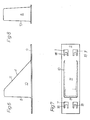
- FIG. 1 shows an oblique view
- FIG. 2 shows a side view
- FIG. 3 shows this from above
- FIG. 4 shows an embodiment of the invention.
- 5 and 13 show an oblique view
- FIG. 15 shows a nose view of variants
- FIGS. 8 and 16 show a front view
- FIGS. 6 to 14 show variants that can be connected to the supporting part by a plug connection 9 to 11 different positions of the plug connections are shown in side view and partial section.
- Fig. 12 shows a detail of the connector in an oblique view.
- 17 to 20d show schematically possible cross-sectional shapes of the catch nose, the configurations according to FIGS. 18, 20, 22 and 10, 12, 20d being stackable.
- 21 to 24 show possible configurations of the end parts of the support part.
- 25 to 27 schematically show possible variants of the side view of the catch noses.
- 28 to 31 show a side view of different variants of holding deposits of the supporting part for fastening the supporting part to the roof or roof battens or tiles in a side view.
- 32 shows a side view
- FIG. 33 a view from above
- FIG. 34 a front view of a supporting part in a plug connection alone.
- 35 to 38 show side view variants of suspension options.
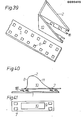
- Fig. 39 shows an oblique view of a variant of a support member and Fig. 40 in side view and Fi g . 41 a top view of another variant.
- an essentially flat supporting part 1 carries a catch lug 2 or is formed in one piece with one.
- the catch nose / has a catch part 8 extending approximately perpendicular to the supporting part and then a support part 11.
- the support part 11 and / or the catch part 8 is supported by at least one support wall 10.
- a separate fastening part can be used to hang the support part 1 into a tile or batten, this roof attachment part can also have a shape of its end parts shown in FIGS. 35 to 39 for the support parts.
- the holding part 1 is fastened directly to a roof batten or formwork 19 with nails which are punched through nail holes 12 of the holding part 1 and in FIG. 29 is fastened to the roof batten 19 with a holding shoulder 5.
- the attachment to a brick 20 is shown with a design encompassing the brick and in Fig. 19 the shape of the holding step is adapted to a particular brick shape which can be varied according to the brick shape.
- the cross section of the catch lug 2 can have one of the shapes shown in FIGS. 17 to 24. Side view possibilities are shown in FIGS. 25 to 27, passages 25 being provided for pushing through and fastening holding rods.
- an embodiment is shown, which is formed in one piece, wherein the retaining lug 2 is deep drawn from the sheet material of the supporting part 1 or is injection molded together with the supporting part from plastic. There is also a welded joint between an extra manufactured catch 2 and a support part 1 possible. A screw or adhesive connection can also be used.
- the other variants show plug connections between the supporting part 1 and the catch lug 2.
- the variants of the catch part can have a fixed connection instead of the plug connection.
- the shape of the catch nose can also be formed from a plastic instead of sheet metal.
- 5 to 8 show the variant of the catch nose shown in FIG. 1 with a plug connection, eyelets 6 being provided in the supporting part. These eyelets 6 were formed with a ramming and drawing machine. In a fastening web 9, which is integral with the catch lug 2, recesses 7 are punched into which the lugs 18 protrude. The lugs 18 serve to fasten the catch lug 2 to the support part; they are inserted into the openings of the eyelets 6, which means that they are attached.
- the support walls 10 are connected via a support part, which simultaneously forms the snow guard wall, and the retaining lugs 18 are formed on a further lower bend.
- 39 shows a variant in which the support walls 10 connect to a front support wall, the catching part 8. Further variants can be produced by punching out and bending a sheet metal part. Of course, it is possible for all plug connections to be varied as shown in FIGS. 40 and 41.
- the lugs 5 are formed from the supporting part by punching and bending and engage in openings 7 in the fastening web 9 of the catch lug.
- the cross-sectional shapes of the catch nose can be varied, as shown as an example in FIGS. 17 to 20 d, it being possible to have recesses 25 in the support walls 10, which may have the shapes shown in FIGS.
- 21 to 24 show possible configurations of the end parts of the supporting part for attachment to the roof or rafters 19 and roof tiles 20, as is shown in detail in FIGS. 28 to 31 and with bends in FIGS. 32 and 33 and 34 to 37 is shown.
- An adjustable snow guard nose in the appropriate shape can be used for a variety of slat distances will.
- the individual details shown can be interchanged.
- the support walls 10 can be inclined and meet at an edge, they can be connected to a front holding surface or an upper holding surface, as shown in the exemplary embodiments, but other connections of the supporting walls are also possible.
- the eyelet bends 6 or nose bends can be provided individually in one row or in multiple rows, it is also possible to provide several rows of fastening designs one behind the other and next to one another on the catch lug 2. This allows the catch lug 2 to be variably attached to the support part 1.
- different types of connections that are detachable, pluggable, but also adhesive r u. Like. Can be formed are possible.
Landscapes
- Engineering & Computer Science (AREA)
- Architecture (AREA)
- Civil Engineering (AREA)
- Structural Engineering (AREA)
- Buildings Adapted To Withstand Abnormal External Influences (AREA)
- Catching Or Destruction (AREA)
- Roof Covering Using Slabs Or Stiff Sheets (AREA)
Abstract
Description
- Die Erfindung bezieht sich auf einen Dachschneefänger mit einem flach auf dem Dach liegenden Tragteil und einer Schneefangnase mit einem Stützteil und/oder mit einem sich senkrecht zum Tragteil mindestens über einen Teil der Breite des Tragteiles erstreckenden Fangteil.
- Derartige Schneefanghalter sind bekannt. Bei den bekannten Ausführungen ist der an die dreieckförmige Schneefangnase an deren Unterseite anschließende Schließteil parallel zum Tragteil verlaufend unter oder über diesem geführt und mit diesem verbunden. Es hat sich gezeigt, daß, bedingt durch den Schneedruck, diese Befestigungsstelle stark belastet ist und die Gefahr eines Aufreißens besteht. Desgleichen besteht die Gefahr, daß die Schneefangnase durch den Druck auf den Fangteil den Stützteil knickt und dadurch die Schneefangnase verbogen wird.
- Die vorliegende Erfindung beseitigt diese Nachteile dadurch, daß der Stützteil und/oder der Fangteil durch mindestens eine Stützwand auf dem Tragteil abgestützt ist. Die Stützwand steht dabei etwa senkrecht auf Stütz- und/oder Fangteil und bildet dabei eine Aussteifungswand, die verhindert, daß der Stützteil oder Fangteil geknickt wird. Darüberhinaus kann die Befestigung der Schneefangnase mit dem Tragteil nicht nur im Bereich des Stützteiles bzw. des Fangteiles, sondern über die ganze Länge der Stützwand erfolgen, wodurch die Gefahr eines Aufreissens und Ausreissens der Schneefangnase, also die Trennung der Verbindung der Schneefangnase mit dem Tragteil, vermieden wird.
- Insbesondere wird vorgeschlagen, daß Stützteil und/oder Fangteil an ihren Rändern durch zwei Stützwände verbunden sind. Die Aussteifung der Nase wird dadurch verdoppelt und man erhält eine starre Schneefangnase. Der Stützteil und die Stützwände können dabei mit dem Tragteil starr verbunden sein. Es ist auch möglich, daß der Stützteil, Fangteil und Stützwand aus dem Tragteil gezogen sind. Durch einen Ziehvorgang läßt sich, bespielsweise aus einem metallischen Tragteil die Schneefangnase ziehen und ist einstückig mit dem Tragteil, absolut sicher verbunden.
- Darüberhinaus ist durch die einstückige Konstruktion eine sichere Aussteifung gegeben. Einen weiteren Vorteil erhält man, wenn Stütz- und Fangteil und die Stützwände zueinander geneigt sind und die Bodenfläche der Fangnase zur Ermöglichung eines Stapelns der Nasen ineinander offen ist.
- Bisher war es so, daß jede gebogene Schneefangnase einen relativ großen Platzbedarf und Verpackungsbedarf bei der Versendung hatte. Durch die Stapelung wird der Platz für Versand und Lagerhaltung ganz wesentlich verringert.
- Bekannt ist es, die Schneefangnasen durch Stäbe zu verbinden, die den Schnee zwischen den Nasen halten. Es mußten bisher eigene Befestigungsvorrichtungen an den Nasen angeordnet werden . Um dies zu vereinfachen, wird vorgeschlagen, daß in der oder den Stützwänden Ausnehmungen oder Durchlässe zur Befestigung von an sich bekannten Verbindungsstangen vorgesehen sind. Es sind lediglich Bohrungen oder Durchlässe, evtl. mit Verstärkungen in den bereits vorhandenen Stützwänden vorzusehen, die ohne großen Arbeitsaufwand angefertigt werden können. Falls die Schneefangnasen gespritzt werden, könnte die Spritzform bereits so ausgebildet sein, daß die Ausnehmungen vorhanden sind. Beim Tiefziehen ist es zweckmäßig, Bohrungen bzw. Stanzungen, Durchlässe vorzusehen.
- Die Dachschneefänger können aus Metall, z.B. mit gezogenen Nasen, aber auch aus Kunststoff, aber auch aus einem Tragteil aus Metall und einem Fangteil aus Kunststoff oder aus weiteren Variationen verschiedener geeigneter Materialien gefertigt werden, wobei beide Teile in geeigneter materialangepaßter Weise gefertigt werden können. Es ist auch möglich, daß Stützteil, Fangteil und/oder die Stützwand oder Stützwände an ihrem unteren Ende Befestigungsausbildungen aufweisen, die mit korrespondierenden Befestigungsausbildungen am Tragteil verbindbar sind. Dabei kann das Material vom Tragteil und Fangnase gleich oder unterschiedlich, also Metall und Kunststoff oder nur Metall oder nur Kunststoff sein. Es ist dadurch möglich, flache Tragteile getrennt und kompakt zu verbinden und die Schneefangnasen gleichfalls gestapelt zu versenden. Es können unterschiedliche Ausbildungen von Schneefangnasen mit einer der jeweiligen Dachneigung am besten entsprechenden Form auf ein- und denselben Tragteil austauschbar befestigt werden. Zu einer Art von Tragteil könnten unterschiedliche Schneefangnasen verwendet werden. Andererseits ist es möglich, auch die Tragteile zum Anpassen an die jeweilige Dachform, also zum Nageln an das Dach oder zum Einhängen in Ziegel, zum Einhängen in Dachlatten od. dgl. zu variieren und zu den unterschiedlichen Tragteilen die zweckmäßigste Form der Schneefangnase zu wählen. Die Befestigung kann durch Schrauben, Nieten aber auch durch Anschweißen od. dgl. erfolgen.
- Besonders einfach ist es, wenn die Befestigungsausbildung eine Steckverbindung ist.
- Die Erfindung ist an Hand von in den Zeichnungen dargestellten Ausführungsbeispielen näher erläutert, ohne sich darauf zu beschränken.
- Fig. 1 zeigt in Schrägansicht, Fig. 2 in Seitansicht, Fig.3 dazu in Ansicht von oben und Fig. 4 dazu in Frontansicht ein Ausführungsbeispiel der Erfindung. Fig. 5 und 13 zeigt in Schrägansicht, Fig. 15 dazu in Ansicht von unten Varianten einer Nase, Fig. 8 und 16 dazu eine Frontansicht und Fig. 6 bis 14 Varianten, die mit dem Tragteil durch eine Steckverbindung verbunden werden kann, wobei in Fig. 9 bis 11 verschiedene Stellungen der Steckverbindungen in Seitansicht und Teilschnitt gezeigt sind. Fig. 12 zeigt ein Detail der Steckverbindung in Schrägansicht. Die Fig. 17 bis 20d zeigen schematisch mögliche Querschnittsformen der Fangnase, wobei die Ausbildungen nach den Fig. 18, 20, 22 und 10, 12, 20d stapelbar sind. Fig. 21 bis 24 zeigen mögliche Ausbildungen der Endteile des Tragteiles. Die Fig. 25, 26 und 27 zeigen schematisch mögliche Varianten der Seitansicht der Fangnasen. Die Fig. 28 bis 31 zeigen in Seitansicht verschiedene Varianten von Halteabsetzungen des Tragteiles zur Befestigung des Tragteiles am Dach bzw. Dachlatten bzw. Ziegel in Seitansicht. Fig. 32 zeigt in Seitenansicht, Fig. 33 in Ansicht von oben und Fig. 34 in Frontansicht einen Tragteil in Steckverbindung allein. Die Fig. 35 bis 38 zeigen in Seitenansicht Varianten von Einhängemöglichkeiten. Fig. 39 zeigt in Schrägansicht eine Variante eines Stützteiles und Fig. 40 in Seitansicht und Fig. 41 dazu eine Ansicht von oben einer weiteren Variante.
- In den Ausführungsbeispielen trägt ein im wesentlichen flacher Tragteil 1 eine Fangnase 2 bzw. ist mit einer 2 solchen einstückig ausgebildet. Die Fangnase/weist einen etwa senkrecht zum Tragteil sich erstreckenden Fangteil 8 und daran anschließend einen Stützteil 11 auf. Der Stützteil 11 und/oder der Fangteil 8 ist durch mindestens eine Stützwand 10 abgestützt. Ein gesonderter Befestigungsteil kann zum Einhängen des Tragteils 1 in einen Ziegel oder Dachlatte dienen, wobei dieser Dachbefestigungsteil auch eine in der Fig. 35 bis 39 für die Tragteile gezeigte Form seiner Endteile haben kann. In Fig. 28 ist der Halteteil 1 direkt mit Nägeln, die durch Nagellöcher 12 des Halteteiles 1 geschlagen werden, an einer Dachlatte oder Schalung 19 befestigt und in Fig. 29 mit einer Halteabsetzung 5 an der Dachlatte 19 befestigt. In Fig. 30 ist die Befestigung an einem Ziegel 20 mit einer den Ziegel umgreifenden Gestaltung gezeigt und in Fig. 19 ist die Form der Halteabsetzung einer besonderen Ziegelform angepaßt, die entsprechend der Ziegelform variiert werden kann.
- Der Querschnitt der Fangnase 2 kann eine der in den Fig. 17 bis 24 gezeigten Formen haben. Möglichkeiten der Seitenansicht sind in den Fig. 25 bis 27 gezeigt, wobei Durchlässe 25 zum Durchschieben und Befestigen von Haltestangen vorgesehen sind.
- In den Fig. 1 bis 4 ist ein Ausführungsbeispiel gezeigt, welches einstückig ausgebildet ist, wobei die Haltenase 2 aus dem Blechmaterial des Tragteiles 1 tief gezogen ist oder samt dem Tragteil aus Kunststoff gespritzt ist. Es ist auch eine Schweißverbindung zwischen einer extra gefertigten Fangnase 2 und einem Tragteil 1 möglich. Ebenso kann eine Schraub- oder Klebeverbindung verwendet werden.
- Die weiteren Varianten zeigen Steckverbindungen zwischen dem Tragteil 1 und der Fangnase 2. Selbstverständlich können die Varianten des Fangteiles statt der Steckverbindung eine feste Verbindung haben. Die Form der Fangnase kann auch statt aus Blech aus einem Kunststoff gebildet sein. Die Fig.5 bis 8 zeigen die in Fig. 1 gezeigte Variante der Fangnase mit einer Steckverbindung, wobei ösen 6 im Tragteil vorgesehen sind. Diese ösen 6 sind mit einer Stampf- und Ziehmaschine gebildet worden. In einen Befestigungssteg 9, der einstückig mit der Fangnase 2 ist, sind Ausnehmungen 7 gestanzt, in die Nasen 18 ragen. Die Nasen 18 dienen zur Befestigung der Fangnase 2 am Tragteil; sie werden in die öffnungen der ösen 6 eingeschoben, wodurch die Befestigung erfolgt.
- Da mehrere Reihen solcher Ösen 6 vorgesehen sind, ist es möglich, die Lage der Fangnase am Befestigungsteil je nach Erfordernis zu verändern. Dies ist an Hand der Fig. 9 bis 12 im Detail gezeigt. Fig. 13 bis 16 zeigen eine Variante sowohl der Ausbildung der Fangnase 2 als auch der Steckverbindung. Die Fangnase 2 ist aus einem Blechteil gebogen.
- Die Stützwände 10 sind über einen Stützteil, der gleichzeitig die Schneefangwand bildet, verbunden und die Haltenasen 18 sind an einer weiteren unteren Abbiegung angeformt. Die Fig. 39 zeigt dazu eine Variante, bei welcher die Stützwände 10 an eine vordere Stützwand, dem Fangteil 8 anschließen. Weitere Varianten lassen sich durch Ausstanzen und Biegen eines Blechteiles herstellen. Selbstverständlich ist es bei allen Steckverbindungen möglich, diese wie in Fig. 40 und 41 gezeigt, zu variieren. Dabei sind die Nasen 5 aus dem Tragteil durch Stanzen und Biegen geformt und greifen in öffnungen 7 im Befestigungssteg 9 der Fangnase ein. Die Querschnittsformen der Fangnase können, wie in den Fig. 17 bis 20d als Beispiel gezeigt ist, variiert werden, wobei es möglich ist, in den Stützwänden 10 Ausnehmungen 25, die beispielsweise die in den Fig. 25, 26, 27 gezeigte Formen haben können, anzuordnen, durch die Verbindungsstäbe zum Halten der Schneelast geschoben werden können. Die Fig. 21 bis 24 zeigen mögliche Ausbildungen der Endteile des Tragteiles zur Bfestigung am Dach bzw. Dachsparren 19 und Dachziegel 20, wie dies im Detail in den Fig. 28 bis 31 und mit Aufbiegungen in den Fig. 32 und 33 sowie 34 bis 37 gezeigt ist.
- Eine verstellbare Schneefangnase in der jweils geeigneten Form kann für die verschiedensten Lattenabstände verwendet werden. Selbstverständlich lassen die Ausführungsbeispiele Varianten offen, die in den Rahmen der Erfindung fallen. So können die einzelnen gezeigten Details untereinander vertausctt sein. Die Stützwände 10 können schräg gestellt sein und an einer Kante zusammentreffen, sie können an einer vorderen Haltefläche oder aber einer oberen Haltefläche angeschlossen sein, wie dies in den Ausführungsbeispielen gezeigt ist, aber auch andere Verbindungen der Stützwände sind möglich. Am Tragteil 1 können die ösenaufbiegungen 6 bzw. Nasenaufbiegungen einzeln einreihig oder mehrreihig vorgesehen sein, es ist auch möglich auf der Fangnase 2 mehrere Reihen von Befestigungsausbildungen hintereinander und nebeneinander vorzusehen. Dadurch kann auf dem Tragteil 1 die Fangnase 2 variabel befestigt werden. Auch anders geartete Verbindungen, die lösbar, steckbar, aber auch klebb r u. dgl. ausgebildet sein können, sind möglich.
Claims (8)
Applications Claiming Priority (2)
| Application Number | Priority Date | Filing Date | Title |
|---|---|---|---|
| AT1955/82 | 1982-05-17 | ||
| AT0195582A AT380295B (de) | 1982-05-17 | 1982-05-17 | Dachschneefaenger |
Publications (3)
| Publication Number | Publication Date |
|---|---|
| EP0095455A2 true EP0095455A2 (de) | 1983-11-30 |
| EP0095455A3 EP0095455A3 (en) | 1984-11-07 |
| EP0095455B1 EP0095455B1 (de) | 1987-08-12 |
Family
ID=3524657
Family Applications (1)
| Application Number | Title | Priority Date | Filing Date |
|---|---|---|---|
| EP83890085A Expired EP0095455B1 (de) | 1982-05-17 | 1983-05-17 | Dachschneefänger |
Country Status (3)
| Country | Link |
|---|---|
| EP (1) | EP0095455B1 (de) |
| AT (2) | AT380295B (de) |
| DE (1) | DE3372999D1 (de) |
Cited By (6)
| Publication number | Priority date | Publication date | Assignee | Title |
|---|---|---|---|---|
| US5205088A (en) * | 1992-02-21 | 1993-04-27 | Mueller George B | Roofing snow panel and method of constructing same |
| DE29707223U1 (de) * | 1997-04-22 | 1997-07-24 | Fleck, Oskar, 45711 Datteln | Schneebremse |
| US5943826A (en) * | 1997-05-20 | 1999-08-31 | Totin; Jody J. | Snow guard |
| DE19806885C2 (de) * | 1997-02-20 | 1999-12-16 | Oskar Fleck | Schneebremse |
| US20100236155A1 (en) * | 2009-03-21 | 2010-09-23 | Carlo John Lanza | Protective covering for roof mounted systems |
| US8869470B2 (en) | 2009-03-21 | 2014-10-28 | Carlo John Lanza | Protective covering for roof device |
Families Citing this family (2)
| Publication number | Priority date | Publication date | Assignee | Title |
|---|---|---|---|---|
| AT382413B (de) * | 1985-04-01 | 1987-02-25 | Dachan Anstalt | Dachschneefaenger |
| DE102009032639A1 (de) * | 2009-07-10 | 2011-01-13 | BWK-Dachzubehör GmbH | Schneestoppbügel |
Family Cites Families (8)
| Publication number | Priority date | Publication date | Assignee | Title |
|---|---|---|---|---|
| US834081A (en) * | 1906-04-12 | 1906-10-23 | Henry N Sieger | Snow guard and fender. |
| US1366703A (en) * | 1919-09-18 | 1921-01-25 | Francis A Peter | Snow-guard |
| US1863561A (en) * | 1929-11-05 | 1932-06-21 | Richard J Brinker | Snow guard |
| CH306932A (de) * | 1952-10-07 | 1955-05-15 | Schoop Traugott | Schneefangvorrichtung an einer Metallbedachung. |
| AT359729B (de) * | 1976-11-02 | 1980-11-25 | Ess Norbert | Schneehaken |
| DE7727905U1 (de) * | 1977-09-09 | 1978-01-05 | Sauter, Ernst, 7475 Messtetten | Dachschneefänger |
| DE7800625U1 (de) * | 1978-01-11 | 1978-04-27 | Fa. Nikolaus Kopp, 7745 Schonach | Schneefanghaken für geneigte Dächer |
| DE7805740U1 (de) * | 1978-02-25 | 1978-12-21 | Glaromat Ag, Glarus (Schweiz) | Schneehalter |
-
1982
- 1982-05-17 AT AT0195582A patent/AT380295B/de not_active IP Right Cessation
-
1983
- 1983-05-17 DE DE8383890085T patent/DE3372999D1/de not_active Expired
- 1983-05-17 EP EP83890085A patent/EP0095455B1/de not_active Expired
- 1983-05-17 AT AT83890085T patent/ATE28915T1/de not_active IP Right Cessation
Cited By (7)
| Publication number | Priority date | Publication date | Assignee | Title |
|---|---|---|---|---|
| US5205088A (en) * | 1992-02-21 | 1993-04-27 | Mueller George B | Roofing snow panel and method of constructing same |
| DE19806885C2 (de) * | 1997-02-20 | 1999-12-16 | Oskar Fleck | Schneebremse |
| DE29707223U1 (de) * | 1997-04-22 | 1997-07-24 | Fleck, Oskar, 45711 Datteln | Schneebremse |
| US5943826A (en) * | 1997-05-20 | 1999-08-31 | Totin; Jody J. | Snow guard |
| US20100236155A1 (en) * | 2009-03-21 | 2010-09-23 | Carlo John Lanza | Protective covering for roof mounted systems |
| US8316592B2 (en) * | 2009-03-21 | 2012-11-27 | Carlo John Lanza | Protective covering for roof mounted systems |
| US8869470B2 (en) | 2009-03-21 | 2014-10-28 | Carlo John Lanza | Protective covering for roof device |
Also Published As
| Publication number | Publication date |
|---|---|
| DE3372999D1 (en) | 1987-09-17 |
| EP0095455B1 (de) | 1987-08-12 |
| AT380295B (de) | 1986-05-12 |
| ATE28915T1 (de) | 1987-08-15 |
| ATA195582A (de) | 1985-09-15 |
| EP0095455A3 (en) | 1984-11-07 |
Similar Documents
| Publication | Publication Date | Title |
|---|---|---|
| DE2832430C3 (de) | Aufhängevorrichtung zum Befestigen einer Gipskartonplatte an einem Trageteil eines Traggerüsts einer Wand | |
| DE9304976U1 (de) | Mit Dachziegeln versehenes Schrägdach und bei einem solchen Dach anzuwendender Dachziegelhaken | |
| EP3315874B1 (de) | Geteilt ausgebildeter dachhaken für hohe belastungen | |
| DE19623956C1 (de) | Als Blechformteil hergestellter Ausleger | |
| EP0095455B1 (de) | Dachschneefänger | |
| DE2639552C2 (de) | Halterung für eine Bauwerksverkleidung | |
| EP0356820B1 (de) | Wandhalterung für Fassadenbegrünung | |
| DE3342453C2 (de) | Reißverschlußschieber | |
| DE2207833C3 (de) | Zaun | |
| DE7800625U1 (de) | Schneefanghaken für geneigte Dächer | |
| AT508615B1 (de) | Schneefanghaken | |
| CH650824A5 (en) | Jointed strip grid ceiling | |
| EP0337461B1 (de) | Firstentlüftungssystem | |
| DE102015121145A1 (de) | First- oder Gratlattenanordnung | |
| DE4419920C2 (de) | Traufenlüftungsprofil | |
| DE3249782C2 (de) | ||
| DE3317334C1 (de) | Firstlattenhalter | |
| DE69100123T2 (de) | Aufhängesystem für ein leichtes Paneel, wie zum Beispiel ein Kalender und Vorrichtung zur Befestigung. | |
| DE3113804C2 (de) | Steigtritt für pfannen-, schiefer- oder plattengedeckte Dächer | |
| CH479783A (de) | Decken- oder Wandverkleidung nach der Trockenbauweise | |
| EP0952273B1 (de) | Dachrinnen-Laubfänger | |
| DE7703230U1 (de) | Hakenteil zum aufhaengen von gegenstaenden an lochplatten | |
| EP1469142B1 (de) | Vorrichtung zur Aufnahme von Baumaterial, insbesondere von Fassaden-Wärmedämmplatten | |
| DE2106707C3 (de) | Geflügel-Elterntier-Batterie | |
| EP0193522B1 (de) | Gegensickenverstärkte Schneefangnasen |
Legal Events
| Date | Code | Title | Description |
|---|---|---|---|
| PUAI | Public reference made under article 153(3) epc to a published international application that has entered the european phase |
Free format text: ORIGINAL CODE: 0009012 |
|
| AK | Designated contracting states |
Designated state(s): AT CH DE FR IT LI |
|
| ITCL | It: translation for ep claims filed |
Representative=s name: STUDIO LUNATI & MANZONI |
|
| EL | Fr: translation of claims filed | ||
| PUAL | Search report despatched |
Free format text: ORIGINAL CODE: 0009013 |
|
| AK | Designated contracting states |
Designated state(s): AT CH DE FR IT LI |
|
| 17P | Request for examination filed |
Effective date: 19841207 |
|
| 17Q | First examination report despatched |
Effective date: 19860122 |
|
| ITF | It: translation for a ep patent filed | ||
| GRAA | (expected) grant |
Free format text: ORIGINAL CODE: 0009210 |
|
| AK | Designated contracting states |
Kind code of ref document: B1 Designated state(s): AT CH DE FR IT LI |
|
| REF | Corresponds to: |
Ref document number: 28915 Country of ref document: AT Date of ref document: 19870815 Kind code of ref document: T |
|
| REF | Corresponds to: |
Ref document number: 3372999 Country of ref document: DE Date of ref document: 19870917 |
|
| ET | Fr: translation filed | ||
| PLBE | No opposition filed within time limit |
Free format text: ORIGINAL CODE: 0009261 |
|
| STAA | Information on the status of an ep patent application or granted ep patent |
Free format text: STATUS: NO OPPOSITION FILED WITHIN TIME LIMIT |
|
| 26N | No opposition filed | ||
| PGFP | Annual fee paid to national office [announced via postgrant information from national office to epo] |
Ref country code: CH Payment date: 19910527 Year of fee payment: 9 |
|
| PGFP | Annual fee paid to national office [announced via postgrant information from national office to epo] |
Ref country code: FR Payment date: 19910530 Year of fee payment: 9 |
|
| ITTA | It: last paid annual fee | ||
| PGFP | Annual fee paid to national office [announced via postgrant information from national office to epo] |
Ref country code: DE Payment date: 19910722 Year of fee payment: 9 |
|
| PG25 | Lapsed in a contracting state [announced via postgrant information from national office to epo] |
Ref country code: LI Effective date: 19920531 Ref country code: CH Effective date: 19920531 |
|
| PG25 | Lapsed in a contracting state [announced via postgrant information from national office to epo] |
Ref country code: FR Effective date: 19930129 |
|
| REG | Reference to a national code |
Ref country code: CH Ref legal event code: PL |
|
| PG25 | Lapsed in a contracting state [announced via postgrant information from national office to epo] |
Ref country code: DE Effective date: 19930202 |
|
| REG | Reference to a national code |
Ref country code: FR Ref legal event code: ST |
|
| PGFP | Annual fee paid to national office [announced via postgrant information from national office to epo] |
Ref country code: AT Payment date: 19931118 Year of fee payment: 11 |
|
| PG25 | Lapsed in a contracting state [announced via postgrant information from national office to epo] |
Ref country code: AT Effective date: 19940517 |