EP0095455A2 - Piège à neige pour toits - Google Patents
Piège à neige pour toits Download PDFInfo
- Publication number
- EP0095455A2 EP0095455A2 EP83890085A EP83890085A EP0095455A2 EP 0095455 A2 EP0095455 A2 EP 0095455A2 EP 83890085 A EP83890085 A EP 83890085A EP 83890085 A EP83890085 A EP 83890085A EP 0095455 A2 EP0095455 A2 EP 0095455A2
- Authority
- EP
- European Patent Office
- Prior art keywords
- supporting
- support
- catch
- roof
- supporting part
- Prior art date
- Legal status (The legal status is an assumption and is not a legal conclusion. Google has not performed a legal analysis and makes no representation as to the accuracy of the status listed.)
- Granted
Links
Images




Classifications
-
- E—FIXED CONSTRUCTIONS
- E04—BUILDING
- E04D—ROOF COVERINGS; SKY-LIGHTS; GUTTERS; ROOF-WORKING TOOLS
- E04D13/00—Special arrangements or devices in connection with roof coverings; Protection against birds; Roof drainage ; Sky-lights
- E04D13/10—Snow traps ; Removing snow from roofs; Snow melters
Definitions
- the invention relates to a roof snow catcher with a support part lying flat on the roof and a snow guard nose with a support part and / or with a catch part extending perpendicularly to the support part at least over part of the width of the support part.
- Such snow catchers are known.
- the closing part adjoining the triangular snow guard nose on its underside is guided parallel to the supporting part below or above and connected to the latter. It has been shown that due to the snow pressure, this attachment point is heavily loaded and there is a risk of tearing open. Likewise, there is a risk that the snow guard nose kinks the support part due to the pressure on the catching part and the snow guard nose is thereby bent.
- the present invention eliminates these disadvantages in that the supporting part and / or the catching part is supported on the supporting part by at least one supporting wall.
- the support wall is approximately perpendicular to the support and / or catch part and thereby forms a stiffening wall which prevents the support part or catch part from being bent.
- the snow guard nose can be attached to the support part not only in the area of the support part or the catch part, but over the entire length of the support wall, which means that there is a risk of the snow guard nose tearing open and tearing, i.e. the separation of the connection of the snow guard nose to the support part, is avoided.
- the support part and / or catch part are connected at their edges by two support walls. This doubles the stiffening of the nose and you get a rigid snow guard nose.
- the support part and the support walls can be rigidly connected to the support part. It is also possible for the support part, catch part and support wall to be pulled out of the support part. By pulling, the snow guard nose can be pulled, for example, from a metallic support part and is connected in one piece to the support part, absolutely securely.
- the one-piece construction provides secure stiffening.
- a further advantage is obtained if the support and catch part and the support walls are inclined to one another and the bottom surface of the catch is open to enable the noses to be stacked one inside the other.
- each curved snow guard nose required a relatively large amount of space and packaging for shipping.
- the stacking significantly reduces the space for shipping and warehousing.
- the roof snow catcher may consist of metal, for example with solid lugs, but also plastic, but also of a supporting part made of metal and a collecting part made of plastic or other variations of different suitable materials are manufactured, the two parts can be manufactured in a suitable material is p condimentter manner . It is also possible for the supporting part, catching part and / or the supporting wall or supporting walls to have fastening designs at their lower end which can be connected to corresponding fastening designs on the supporting part.
- the material of the supporting part and catch nose can be the same or different, that is metal and plastic or only metal or only plastic. This makes it possible to connect flat support parts separately and compactly and to send the snow guard lugs stacked as well.
- snow guard lugs with a shape that best corresponds to the respective roof pitch can be exchangeably attached to one and the same supporting part.
- Different snow catcher noses could be used for one type of support part.
- the supporting parts can be used to adapt to the respective roof shape, i.e. for nailing to the roof or for hanging in bricks, for hanging in roof battens or the like, and to choose the most appropriate shape of the snow guard nose for the different supporting parts.
- the attachment can be done by screws, rivets or by welding or the like.
- attachment training is a plug connection.
- FIG. 1 shows an oblique view
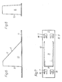
- FIG. 2 shows a side view
- FIG. 3 shows this from above
- FIG. 4 shows an embodiment of the invention.
- 5 and 13 show an oblique view
- FIG. 15 shows a nose view of variants
- FIGS. 8 and 16 show a front view
- FIGS. 6 to 14 show variants that can be connected to the supporting part by a plug connection 9 to 11 different positions of the plug connections are shown in side view and partial section.
- Fig. 12 shows a detail of the connector in an oblique view.
- 17 to 20d show schematically possible cross-sectional shapes of the catch nose, the configurations according to FIGS. 18, 20, 22 and 10, 12, 20d being stackable.
- 21 to 24 show possible configurations of the end parts of the support part.
- 25 to 27 schematically show possible variants of the side view of the catch noses.
- 28 to 31 show a side view of different variants of holding deposits of the supporting part for fastening the supporting part to the roof or roof battens or tiles in a side view.
- 32 shows a side view
- FIG. 33 a view from above
- FIG. 34 a front view of a supporting part in a plug connection alone.
- 35 to 38 show side view variants of suspension options.
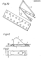
- Fig. 39 shows an oblique view of a variant of a support member and Fig. 40 in side view and Fi g . 41 a top view of another variant.
- an essentially flat supporting part 1 carries a catch lug 2 or is formed in one piece with one.
- the catch nose / has a catch part 8 extending approximately perpendicular to the supporting part and then a support part 11.
- the support part 11 and / or the catch part 8 is supported by at least one support wall 10.
- a separate fastening part can be used to hang the support part 1 into a tile or batten, this roof attachment part can also have a shape of its end parts shown in FIGS. 35 to 39 for the support parts.
- the holding part 1 is fastened directly to a roof batten or formwork 19 with nails which are punched through nail holes 12 of the holding part 1 and in FIG. 29 is fastened to the roof batten 19 with a holding shoulder 5.
- the attachment to a brick 20 is shown with a design encompassing the brick and in Fig. 19 the shape of the holding step is adapted to a particular brick shape which can be varied according to the brick shape.
- the cross section of the catch lug 2 can have one of the shapes shown in FIGS. 17 to 24. Side view possibilities are shown in FIGS. 25 to 27, passages 25 being provided for pushing through and fastening holding rods.
- an embodiment is shown, which is formed in one piece, wherein the retaining lug 2 is deep drawn from the sheet material of the supporting part 1 or is injection molded together with the supporting part from plastic. There is also a welded joint between an extra manufactured catch 2 and a support part 1 possible. A screw or adhesive connection can also be used.
- the other variants show plug connections between the supporting part 1 and the catch lug 2.
- the variants of the catch part can have a fixed connection instead of the plug connection.
- the shape of the catch nose can also be formed from a plastic instead of sheet metal.
- 5 to 8 show the variant of the catch nose shown in FIG. 1 with a plug connection, eyelets 6 being provided in the supporting part. These eyelets 6 were formed with a ramming and drawing machine. In a fastening web 9, which is integral with the catch lug 2, recesses 7 are punched into which the lugs 18 protrude. The lugs 18 serve to fasten the catch lug 2 to the support part; they are inserted into the openings of the eyelets 6, which means that they are attached.
- the support walls 10 are connected via a support part, which simultaneously forms the snow guard wall, and the retaining lugs 18 are formed on a further lower bend.
- 39 shows a variant in which the support walls 10 connect to a front support wall, the catching part 8. Further variants can be produced by punching out and bending a sheet metal part. Of course, it is possible for all plug connections to be varied as shown in FIGS. 40 and 41.
- the lugs 5 are formed from the supporting part by punching and bending and engage in openings 7 in the fastening web 9 of the catch lug.
- the cross-sectional shapes of the catch nose can be varied, as shown as an example in FIGS. 17 to 20 d, it being possible to have recesses 25 in the support walls 10, which may have the shapes shown in FIGS.
- 21 to 24 show possible configurations of the end parts of the supporting part for attachment to the roof or rafters 19 and roof tiles 20, as is shown in detail in FIGS. 28 to 31 and with bends in FIGS. 32 and 33 and 34 to 37 is shown.
- An adjustable snow guard nose in the appropriate shape can be used for a variety of slat distances will.
- the individual details shown can be interchanged.
- the support walls 10 can be inclined and meet at an edge, they can be connected to a front holding surface or an upper holding surface, as shown in the exemplary embodiments, but other connections of the supporting walls are also possible.
- the eyelet bends 6 or nose bends can be provided individually in one row or in multiple rows, it is also possible to provide several rows of fastening designs one behind the other and next to one another on the catch lug 2. This allows the catch lug 2 to be variably attached to the support part 1.
- different types of connections that are detachable, pluggable, but also adhesive r u. Like. Can be formed are possible.
Landscapes
- Engineering & Computer Science (AREA)
- Architecture (AREA)
- Civil Engineering (AREA)
- Structural Engineering (AREA)
- Buildings Adapted To Withstand Abnormal External Influences (AREA)
- Catching Or Destruction (AREA)
- Roof Covering Using Slabs Or Stiff Sheets (AREA)
Applications Claiming Priority (2)
| Application Number | Priority Date | Filing Date | Title |
|---|---|---|---|
| AT1955/82 | 1982-05-17 | ||
| AT0195582A AT380295B (de) | 1982-05-17 | 1982-05-17 | Dachschneefaenger |
Publications (3)
| Publication Number | Publication Date |
|---|---|
| EP0095455A2 true EP0095455A2 (fr) | 1983-11-30 |
| EP0095455A3 EP0095455A3 (en) | 1984-11-07 |
| EP0095455B1 EP0095455B1 (fr) | 1987-08-12 |
Family
ID=3524657
Family Applications (1)
| Application Number | Title | Priority Date | Filing Date |
|---|---|---|---|
| EP83890085A Expired EP0095455B1 (fr) | 1982-05-17 | 1983-05-17 | Piège à neige pour toits |
Country Status (3)
| Country | Link |
|---|---|
| EP (1) | EP0095455B1 (fr) |
| AT (2) | AT380295B (fr) |
| DE (1) | DE3372999D1 (fr) |
Cited By (6)
| Publication number | Priority date | Publication date | Assignee | Title |
|---|---|---|---|---|
| US5205088A (en) * | 1992-02-21 | 1993-04-27 | Mueller George B | Roofing snow panel and method of constructing same |
| DE29707223U1 (de) * | 1997-04-22 | 1997-07-24 | Fleck, Oskar, 45711 Datteln | Schneebremse |
| US5943826A (en) * | 1997-05-20 | 1999-08-31 | Totin; Jody J. | Snow guard |
| DE19806885C2 (de) * | 1997-02-20 | 1999-12-16 | Oskar Fleck | Schneebremse |
| US20100236155A1 (en) * | 2009-03-21 | 2010-09-23 | Carlo John Lanza | Protective covering for roof mounted systems |
| US8869470B2 (en) | 2009-03-21 | 2014-10-28 | Carlo John Lanza | Protective covering for roof device |
Families Citing this family (2)
| Publication number | Priority date | Publication date | Assignee | Title |
|---|---|---|---|---|
| AT382413B (de) * | 1985-04-01 | 1987-02-25 | Dachan Anstalt | Dachschneefaenger |
| DE102009032639A1 (de) * | 2009-07-10 | 2011-01-13 | BWK-Dachzubehör GmbH | Schneestoppbügel |
Family Cites Families (8)
| Publication number | Priority date | Publication date | Assignee | Title |
|---|---|---|---|---|
| US834081A (en) * | 1906-04-12 | 1906-10-23 | Henry N Sieger | Snow guard and fender. |
| US1366703A (en) * | 1919-09-18 | 1921-01-25 | Francis A Peter | Snow-guard |
| US1863561A (en) * | 1929-11-05 | 1932-06-21 | Richard J Brinker | Snow guard |
| CH306932A (de) * | 1952-10-07 | 1955-05-15 | Schoop Traugott | Schneefangvorrichtung an einer Metallbedachung. |
| AT359729B (de) * | 1976-11-02 | 1980-11-25 | Ess Norbert | Schneehaken |
| DE7727905U1 (de) * | 1977-09-09 | 1978-01-05 | Sauter, Ernst, 7475 Messtetten | Dachschneefänger |
| DE7800625U1 (de) * | 1978-01-11 | 1978-04-27 | Fa. Nikolaus Kopp, 7745 Schonach | Schneefanghaken für geneigte Dächer |
| DE7805740U1 (de) * | 1978-02-25 | 1978-12-21 | Glaromat Ag, Glarus (Schweiz) | Schneehalter |
-
1982
- 1982-05-17 AT AT0195582A patent/AT380295B/de not_active IP Right Cessation
-
1983
- 1983-05-17 DE DE8383890085T patent/DE3372999D1/de not_active Expired
- 1983-05-17 EP EP83890085A patent/EP0095455B1/fr not_active Expired
- 1983-05-17 AT AT83890085T patent/ATE28915T1/de not_active IP Right Cessation
Cited By (7)
| Publication number | Priority date | Publication date | Assignee | Title |
|---|---|---|---|---|
| US5205088A (en) * | 1992-02-21 | 1993-04-27 | Mueller George B | Roofing snow panel and method of constructing same |
| DE19806885C2 (de) * | 1997-02-20 | 1999-12-16 | Oskar Fleck | Schneebremse |
| DE29707223U1 (de) * | 1997-04-22 | 1997-07-24 | Fleck, Oskar, 45711 Datteln | Schneebremse |
| US5943826A (en) * | 1997-05-20 | 1999-08-31 | Totin; Jody J. | Snow guard |
| US20100236155A1 (en) * | 2009-03-21 | 2010-09-23 | Carlo John Lanza | Protective covering for roof mounted systems |
| US8316592B2 (en) * | 2009-03-21 | 2012-11-27 | Carlo John Lanza | Protective covering for roof mounted systems |
| US8869470B2 (en) | 2009-03-21 | 2014-10-28 | Carlo John Lanza | Protective covering for roof device |
Also Published As
| Publication number | Publication date |
|---|---|
| DE3372999D1 (en) | 1987-09-17 |
| EP0095455B1 (fr) | 1987-08-12 |
| AT380295B (de) | 1986-05-12 |
| ATE28915T1 (de) | 1987-08-15 |
| ATA195582A (de) | 1985-09-15 |
| EP0095455A3 (en) | 1984-11-07 |
Similar Documents
| Publication | Publication Date | Title |
|---|---|---|
| DE2832430C3 (de) | Aufhängevorrichtung zum Befestigen einer Gipskartonplatte an einem Trageteil eines Traggerüsts einer Wand | |
| DE9304976U1 (de) | Mit Dachziegeln versehenes Schrägdach und bei einem solchen Dach anzuwendender Dachziegelhaken | |
| EP3315874B1 (fr) | Crochet de toit conçu en plusieurs pièces pour charges élevées | |
| DE19623956C1 (de) | Als Blechformteil hergestellter Ausleger | |
| EP0095455B1 (fr) | Piège à neige pour toits | |
| DE2639552C2 (de) | Halterung für eine Bauwerksverkleidung | |
| EP0356820B1 (fr) | Treillis pour faire pousser des plantes sur des façades | |
| DE3342453C2 (de) | Reißverschlußschieber | |
| DE2207833C3 (de) | Zaun | |
| DE7800625U1 (de) | Schneefanghaken für geneigte Dächer | |
| AT508615B1 (de) | Schneefanghaken | |
| CH650824A5 (en) | Jointed strip grid ceiling | |
| EP0337461B1 (fr) | Système d'aération de faîtage | |
| DE102015121145A1 (de) | First- oder Gratlattenanordnung | |
| DE4419920C2 (de) | Traufenlüftungsprofil | |
| DE3249782C2 (fr) | ||
| DE3317334C1 (de) | Firstlattenhalter | |
| DE69100123T2 (de) | Aufhängesystem für ein leichtes Paneel, wie zum Beispiel ein Kalender und Vorrichtung zur Befestigung. | |
| DE3113804C2 (de) | Steigtritt für pfannen-, schiefer- oder plattengedeckte Dächer | |
| CH479783A (de) | Decken- oder Wandverkleidung nach der Trockenbauweise | |
| EP0952273B1 (fr) | Capteur de feuilles pour gouttières | |
| DE7703230U1 (de) | Hakenteil zum aufhaengen von gegenstaenden an lochplatten | |
| EP1469142B1 (fr) | Empaquetage pour matériaux de construction, en particulier panneaux d'isolation | |
| DE2106707C3 (de) | Geflügel-Elterntier-Batterie | |
| EP0193522B1 (fr) | Nez pièges à neige renforcés par contre rainurage |
Legal Events
| Date | Code | Title | Description |
|---|---|---|---|
| PUAI | Public reference made under article 153(3) epc to a published international application that has entered the european phase |
Free format text: ORIGINAL CODE: 0009012 |
|
| AK | Designated contracting states |
Designated state(s): AT CH DE FR IT LI |
|
| ITCL | It: translation for ep claims filed |
Representative=s name: STUDIO LUNATI & MANZONI |
|
| EL | Fr: translation of claims filed | ||
| PUAL | Search report despatched |
Free format text: ORIGINAL CODE: 0009013 |
|
| AK | Designated contracting states |
Designated state(s): AT CH DE FR IT LI |
|
| 17P | Request for examination filed |
Effective date: 19841207 |
|
| 17Q | First examination report despatched |
Effective date: 19860122 |
|
| ITF | It: translation for a ep patent filed | ||
| GRAA | (expected) grant |
Free format text: ORIGINAL CODE: 0009210 |
|
| AK | Designated contracting states |
Kind code of ref document: B1 Designated state(s): AT CH DE FR IT LI |
|
| REF | Corresponds to: |
Ref document number: 28915 Country of ref document: AT Date of ref document: 19870815 Kind code of ref document: T |
|
| REF | Corresponds to: |
Ref document number: 3372999 Country of ref document: DE Date of ref document: 19870917 |
|
| ET | Fr: translation filed | ||
| PLBE | No opposition filed within time limit |
Free format text: ORIGINAL CODE: 0009261 |
|
| STAA | Information on the status of an ep patent application or granted ep patent |
Free format text: STATUS: NO OPPOSITION FILED WITHIN TIME LIMIT |
|
| 26N | No opposition filed | ||
| PGFP | Annual fee paid to national office [announced via postgrant information from national office to epo] |
Ref country code: CH Payment date: 19910527 Year of fee payment: 9 |
|
| PGFP | Annual fee paid to national office [announced via postgrant information from national office to epo] |
Ref country code: FR Payment date: 19910530 Year of fee payment: 9 |
|
| ITTA | It: last paid annual fee | ||
| PGFP | Annual fee paid to national office [announced via postgrant information from national office to epo] |
Ref country code: DE Payment date: 19910722 Year of fee payment: 9 |
|
| PG25 | Lapsed in a contracting state [announced via postgrant information from national office to epo] |
Ref country code: LI Effective date: 19920531 Ref country code: CH Effective date: 19920531 |
|
| PG25 | Lapsed in a contracting state [announced via postgrant information from national office to epo] |
Ref country code: FR Effective date: 19930129 |
|
| REG | Reference to a national code |
Ref country code: CH Ref legal event code: PL |
|
| PG25 | Lapsed in a contracting state [announced via postgrant information from national office to epo] |
Ref country code: DE Effective date: 19930202 |
|
| REG | Reference to a national code |
Ref country code: FR Ref legal event code: ST |
|
| PGFP | Annual fee paid to national office [announced via postgrant information from national office to epo] |
Ref country code: AT Payment date: 19931118 Year of fee payment: 11 |
|
| PG25 | Lapsed in a contracting state [announced via postgrant information from national office to epo] |
Ref country code: AT Effective date: 19940517 |