EP0095556B1 - Dispositif de remplissage de sacs avec une matière fluide, spécialement une matière poussièreuse - Google Patents
Dispositif de remplissage de sacs avec une matière fluide, spécialement une matière poussièreuse Download PDFInfo
- Publication number
- EP0095556B1 EP0095556B1 EP83101449A EP83101449A EP0095556B1 EP 0095556 B1 EP0095556 B1 EP 0095556B1 EP 83101449 A EP83101449 A EP 83101449A EP 83101449 A EP83101449 A EP 83101449A EP 0095556 B1 EP0095556 B1 EP 0095556B1
- Authority
- EP
- European Patent Office
- Prior art keywords
- sack
- filling
- flaps
- suction tube
- sealing
- Prior art date
- Legal status (The legal status is an assumption and is not a legal conclusion. Google has not performed a legal analysis and makes no representation as to the accuracy of the status listed.)
- Expired
Links
- 239000000463 material Substances 0.000 title description 10
- 239000012530 fluid Substances 0.000 title 1
- 238000007789 sealing Methods 0.000 claims description 25
- 230000009969 flowable effect Effects 0.000 claims description 2
- 239000000945 filler Substances 0.000 description 19
- 230000001681 protective effect Effects 0.000 description 3
- 230000002411 adverse Effects 0.000 description 2
- 239000013013 elastic material Substances 0.000 description 2
- 238000005429 filling process Methods 0.000 description 2
- 238000007664 blowing Methods 0.000 description 1
- 239000000428 dust Substances 0.000 description 1
- 230000000694 effects Effects 0.000 description 1
- 230000002349 favourable effect Effects 0.000 description 1
- 230000001771 impaired effect Effects 0.000 description 1
- 238000003780 insertion Methods 0.000 description 1
- 230000037431 insertion Effects 0.000 description 1
- 239000002184 metal Substances 0.000 description 1
- 238000007493 shaping process Methods 0.000 description 1
- 238000003466 welding Methods 0.000 description 1
Images


Classifications
-
- B—PERFORMING OPERATIONS; TRANSPORTING
- B65—CONVEYING; PACKING; STORING; HANDLING THIN OR FILAMENTARY MATERIAL
- B65B—MACHINES, APPARATUS OR DEVICES FOR, OR METHODS OF, PACKAGING ARTICLES OR MATERIALS; UNPACKING
- B65B39/00—Nozzles, funnels or guides for introducing articles or materials into containers or wrappers
- B65B39/04—Nozzles, funnels or guides for introducing articles or materials into containers or wrappers having air-escape, or air-withdrawal, passages
-
- B—PERFORMING OPERATIONS; TRANSPORTING
- B65—CONVEYING; PACKING; STORING; HANDLING THIN OR FILAMENTARY MATERIAL
- B65B—MACHINES, APPARATUS OR DEVICES FOR, OR METHODS OF, PACKAGING ARTICLES OR MATERIALS; UNPACKING
- B65B39/00—Nozzles, funnels or guides for introducing articles or materials into containers or wrappers
- B65B39/02—Expansible or contractible nozzles, funnels, or guides
Definitions
- the present invention relates to a device for filling sacks with flowable or free-flowing, in particular dust-shaped filling material, for example for the fully automatic filling of flat and gusseted sacks made of paper, plastic or a combination of these materials, the sacks being used by means of clamping jaws to hold the lateral sack mouth areas transported to the filler neck and the bags are opened there by suction cups arranged between the jaws while simultaneously moving the jaws towards one another.
- From DE-OS 15 86 248 and DE-OS 2418 228 devices are also known in which the sack is pivoted up for placement against the filler neck and the edge of the sack is held in place by expandable clamping jaws. A complete sealing of the edge of the bag is not guaranteed.
- the ratio between the outside diameter of the sleeve and the inside diameter of the bag is determined by the inflating capacity of the sleeve. If the outer diameter of the sleeve is chosen to be only slightly smaller than the inner diameter of the sack, there is a risk of the sack edge turning over when the sack is automatically pushed onto the filler neck. The bags are therefore pushed on by hand. The disadvantage of the possible turning over of the sack edge could be largely avoided by choosing the outside diameter of the sleeve to be considerably smaller than the inside diameter of the sack.
- the object of the present invention is to avoid the disadvantages of the known devices and to create a simple mechanical, preferably fully automatic device, in which a perfect seal is produced during the filling process, so that even when filling bags with dusty, with Protective gas treated or odorous material can be safely avoided.
- this is achieved in a device with devices for holding, transporting and opening the bag by means of expandable flaps which can be lowered into the area of the opened bag edge and a telescopically displaceable surrounding the filler neck and arranged on the filler neck in the extended position, sealed between them, between the spreaders Shaped flaps that can be lowered into the edge of the sack, provided at their lower end with a sealing sleeve, which is arranged on the outside and is known per se.
- the retraction of the unspread mold flaps in the bag edge which is held in a manner known per se by clamping and opened by means of suction cups, ensures that the edge of the bag cannot be folded over and that a crease-free shape of the edge of the bag is achieved in accordance with the cross-section of the filler or sealing nozzle, which preferably have a circular cross-section and the flaps are accordingly designed as semicircular shell segments.
- the dimensionally stable molded flaps which are preferably made from optionally surface-treated sheet metal, plastic or the like, make it possible to make the outer dimensions of the sealing connector or the inflation ring arranged on it only slightly smaller than the internal dimensions of the expanded molded flaps or the sack, so that on the one hand the largest possible filling cross-section of the filling or sealing nozzle can be realized and on the other hand a secure seal is guaranteed.
- sealing segments on the outside in the region of the edge of the sack, with a fixed and stable outer ring at times, against which the sack is pressed by the inflation ring after exposure to a pressure medium.
- an inflatable cuff on the sealing socket, one could also be provided on the outer ring or both on the sealing socket and on the outer ring.
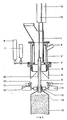
- the sealing nozzle 2 which is telescopically displaceable via the actuator or the like 8, is arranged on the filling nozzle 1.
- the elastic seal 3 is arranged on the lower end of the filler neck in the form of an annular collar, and the stop ring 4 is provided on the upper end of the sealing connector, which could also be designed as an elastic seal or instead of the seal 3.
- the inflating ring which is arranged on the lower end of the sealing socket and is to be connected to a compressed air source, not shown, is designated by 5.
- the pivoted flaps 6 are provided, which are actuated via the actuator or the like 7.
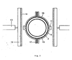
- the sack 15 is held in the still closed state between the supports 14 made of elastic material which are arranged on the inner sides of the transport clamps 12 which preferably extend over most of the sack width and can be actuated by means of the actuators or the like 13.
- 11 denotes the suction cups for opening the sack 15 and 9, the suction pipe 9 which is guided through the filler neck 1 and which can be lowered and raised by means of the actuator or the like 10.
- the bag 15 clamped between the transport clamps 12 with a support 14 was here automatically transported to the filling device and transferred in this position to the lateral clamps 17 (FIG. 7).
- the clamps 17 are closed, the suction devices 11 are placed on the side wall of the bag and, after the transport clamps 12 have been opened, the suction air is switched on via the actuators or the like 13.
- An actuator or the like, not shown, moves the clamps 17 towards one another, while at the same time the suction cups 11 move away from one another and the bag 15 opens.
- the form flaps 6 have been pivoted into the sack edge region and spread apart via the actuator 7, as shown in FIG. 2, so that the sack edge region has an opening cross section corresponding to the design of the form flaps.
- the suction air for the suction cups 11 can be switched off and the sealing neck 2 can now be lowered into the area of the spread-out flaps 6, the stop ring 4 of the sealing neck 2 being pressed onto the elastic sealing ring 3 of the filler neck 1 in the lower end position and thereby filling neck 1 and sealing socket 2 are tightly connected.
- the molded flaps 6 are then moved upwards out of the sack edge area which is still held by the side clamps 17 and thus prevented from collapsing.
- the inflation ring 5 is pressurized with compressed air and the sack 15 is thereby completely sealed from the inside.
- the outer wall of the bag is pressed against the outer segments 16 (FIG. 7) and the bag is thus additionally kept tight from the outside.
- the bag 15 is then filled with a predetermined quantity of filling material.
- the suction pipe 9 is inserted via the actuator 10 into the position shown in FIG. 4, ie into the upper edge of the sack.
- the sealing nozzle 2 is now raised by the actuator 8 and moved out of the bag edge area, tightened the bag edge area by moving the side clamps 17 apart and clamped the bag edge area again by moving the transport clamps 12, the elastic covering 14 of the transport clamps enclosing the suction tube 9 and hermetically sealing it from the outside, so that no air from the outside more can get into the sack ( Figures 5 and 6).
- the part of the suction tube 9 which dips into the edge of the bag is, as shown in FIG. 6, preferably of oval cross-section.
- a flat, slit-shaped cross-section could also be provided, or a larger number of correspondingly small, circular suction openings could be provided in the direction of the sack edge, whereby in any case overstretching of the sack material is avoided and a fold-free return of the sack edge region to an extended position is ensured.
- the vacuum supply line is closed by means of a valve (not shown) before the suction pipe 9 is moved out of the bag edge area and a short compressed air pulse through the suction pipe to free the suction pipe mouth from any adhering contents cleverly.
- the elastic material of the supports 14 seals the edge of the bag immediately behind the end of the suction pipe without creases, so that no air can reach the contents from the outside.
- the flaps 6 are closed, covering the cross section of the filler neck 1 with one another in a tightly closing manner and thus preventing any filling material that may trickle in between the sack walls and into the sack rim area and thereby impair the subsequent closing of the sack in a downstream closing station or by a closing device that can be moved up to it.
- spreading elements such as wedges or the like, which can be inserted into the sack edge area above the transport clamps 12, by means of which this part of the sack edge area is spread apart and makes it possible, for example by blowing out by means of a strong compressed air pulse, to cover this area of approximately to free existing contents.
- the suction pipe 9 does not necessarily have to be arranged passing through the filler neck 1; rather, it could also be provided in a subsequent position in order to increase the performance of the device.
- the suction tube 9 can also be surrounded by a protective tube 18 which can be displaced by means of an actuator 19 and which prevents the filling material adhering to the filling material adhering to this, for example, from becoming dirty when the suction tube is pulled out, and the subsequent closing, for example by welding adversely affected.
- the transport clamps 12 do not necessarily have to be continuous, as can be seen in particular from FIG. 7, but in many cases two clamps arranged only on the side are sufficient, which do not hold the bag in its full width during transport, but only at the ends.
Landscapes
- Engineering & Computer Science (AREA)
- Mechanical Engineering (AREA)
- Supplying Of Containers To The Packaging Station (AREA)
- Basic Packing Technique (AREA)
Claims (8)
Applications Claiming Priority (2)
| Application Number | Priority Date | Filing Date | Title |
|---|---|---|---|
| DE3220780 | 1982-06-02 | ||
| DE19823220780 DE3220780A1 (de) | 1982-06-02 | 1982-06-02 | Vorrichtung zum befuellen von saecken mit fliess- bzw. rieselfoermigem, insbesondere staubfoermigem fuellgut |
Publications (3)
| Publication Number | Publication Date |
|---|---|
| EP0095556A2 EP0095556A2 (fr) | 1983-12-07 |
| EP0095556A3 EP0095556A3 (en) | 1985-03-27 |
| EP0095556B1 true EP0095556B1 (fr) | 1987-01-14 |
Family
ID=6165112
Family Applications (1)
| Application Number | Title | Priority Date | Filing Date |
|---|---|---|---|
| EP83101449A Expired EP0095556B1 (fr) | 1982-06-02 | 1983-02-16 | Dispositif de remplissage de sacs avec une matière fluide, spécialement une matière poussièreuse |
Country Status (2)
| Country | Link |
|---|---|
| EP (1) | EP0095556B1 (fr) |
| DE (2) | DE3220780A1 (fr) |
Families Citing this family (14)
| Publication number | Priority date | Publication date | Assignee | Title |
|---|---|---|---|---|
| DE3427394C2 (de) * | 1984-07-25 | 1987-01-15 | Haver & Boecker, 4740 Oelde | Vorrichtung zum Füllen von offenen Säcken |
| DE3618981A1 (de) * | 1985-07-04 | 1987-01-15 | Duerbeck Papiersackfab | Vorrichtung zum befuellen von ventilsaecken |
| DE3634890A1 (de) * | 1986-10-14 | 1988-04-28 | Haver & Boecker | Vorrichtung zum fuellen und verschliessen von offenen saecken |
| DE3726137A1 (de) * | 1987-08-06 | 1989-02-16 | Haver & Boecker | Vorrichtung zum fuellen von oben offenen saecken |
| DE3814337A1 (de) * | 1988-04-28 | 1989-11-09 | Fix Peter Steimel Gmbh & Co Kg | Verfahren und vorrichtung zur befuellung eines kunststoffsacks |
| IT1280332B1 (it) * | 1995-06-01 | 1998-01-15 | Marco Santucci | Meccanismo per la manipolazione automatica dei sacchi da riempire nelle insaccatrici |
| DE19934148A1 (de) * | 1999-07-26 | 2001-02-01 | Neuhaeuser Gmbh Umwelt Dosier | Vorrichtung zur gasdichten Abdichtung |
| DE20120628U1 (de) | 2001-11-07 | 2002-03-21 | Haver & Boecker, 59302 Oelde | Füllmaschine zum Füllen von Säcken |
| DE10247291A1 (de) * | 2002-10-10 | 2004-04-22 | Weber-Waagenbau und Wägeelektronik GmbH | Füllstation für eine Sackherstellungs- und Befüllmaschine |
| DE102005011813A1 (de) * | 2005-03-15 | 2006-09-21 | Nordenia Deutschland Emsdetten Gmbh | Flexibler Behälter und Vorrichtung zum Befüllen eines flexiblen Behälters |
| DE102011012879A1 (de) | 2011-03-02 | 2012-09-06 | Haver & Boecker Ohg | Vorrichtung und Verfahren zum Befüllen von Ventilsäcken mit schüttfähigen Gütern |
| DK179045B1 (da) | 2016-02-17 | 2017-09-18 | Panpac Eng As | Fremgangsmåde til justering af anlæg for fyldning af storsække, samt anlæg til fyldning af storsække |
| CN105819028B (zh) * | 2016-06-07 | 2019-02-19 | 南通恒力医药设备有限公司 | 用于颗粒物料灌装的可变形漏斗 |
| CN119534048B (zh) * | 2024-10-30 | 2025-12-02 | 自然资源部第二海洋研究所 | 近海沉积物捕获装置 |
Family Cites Families (5)
| Publication number | Priority date | Publication date | Assignee | Title |
|---|---|---|---|---|
| CH308711A (de) * | 1951-10-02 | 1955-07-31 | Continental Can Co | Einrichtung zum Abfüllen von faltbaren Behältern. |
| CH376045A (de) * | 1959-01-24 | 1964-03-15 | Roller Erwin | Pneumatisch wirkende Haltevorrichtung für schlauchartige Verpackungen wie Beutel, Säcke und dergleichen |
| SE378226B (fr) * | 1972-04-26 | 1975-08-25 | Librawerk Pelz & Nagel Kg | |
| US3830266A (en) * | 1973-03-23 | 1974-08-20 | Okinkraft Inc | Drop-down fill spout for bag filling machine |
| US4322932A (en) * | 1980-05-05 | 1982-04-06 | Mcgregor Harold R | Bag filling and handling apparatus |
-
1982
- 1982-06-02 DE DE19823220780 patent/DE3220780A1/de not_active Withdrawn
-
1983
- 1983-02-16 EP EP83101449A patent/EP0095556B1/fr not_active Expired
- 1983-02-16 DE DE8383101449T patent/DE3369103D1/de not_active Expired
Also Published As
| Publication number | Publication date |
|---|---|
| EP0095556A3 (en) | 1985-03-27 |
| EP0095556A2 (fr) | 1983-12-07 |
| DE3220780A1 (de) | 1983-12-08 |
| DE3369103D1 (en) | 1987-02-19 |
Similar Documents
| Publication | Publication Date | Title |
|---|---|---|
| DE2007747C3 (de) | Verfahren und Vorrichtung zum Aufblasen eines auf einer Radfelge aufgezogenen schlauchlosen Reifens | |
| DE2301817A1 (de) | Verfahren und vorrichtung zur vollautomatischen herstellung von gefuellten seitenfaltensaecken aus kunststoff | |
| EP2134608B1 (fr) | Dispositif d'emballage et procédé d'emballage | |
| EP0095556A2 (fr) | Dispositif de remplissage de sacs avec une matière fluide, spécialement une matière poussièreuse | |
| DE69511826T2 (de) | Verfahren und Vorrichtung zum Evakuieren einer mit körnigem Material gefüllten Vakuumverpackung | |
| DE2947872A1 (de) | Absackvorrichtung | |
| EP2103520B1 (fr) | Dispositif de traitement et procédé de traitement d'un sac ouvert rempli de produits au détail | |
| EP1858778A1 (fr) | Contenant souple, procede et dispositif pour remplir un contenant souple | |
| EP3826831B1 (fr) | Dispositif et procédé de fabrication d'au moins un sac ouvert vide | |
| DE3814337C2 (fr) | ||
| EP0726202A1 (fr) | Machine pour la fabrication de sachets plats | |
| EP2132093B1 (fr) | Machine pour remplisser et fermer des sacs, comportant un élément joint polyvalent | |
| EP0498047A1 (fr) | Sachet à fond croisé ou plat avec valve | |
| EP1232850B1 (fr) | Procédé et appareil pour le formage et/ou la fermeture d'un unité d'emballage | |
| DE3441947A1 (de) | Verfahren und vorrichtung zum oeffnen eines flachbeutels | |
| DE3618981C2 (fr) | ||
| DE20001005U1 (de) | Verschlußorgan für Entleerbehälter | |
| DE2834187C2 (de) | Tüten-Abpackmaschine | |
| DE2058652A1 (de) | Verfahren und Vorrichtung zum Entfernen der Luft aus einem Ventilsack | |
| DE8805620U1 (de) | Vorrichtung zur Befüllung eines Kunststoffsacks | |
| EP1145999A1 (fr) | Dispositif de remplissage d' un récipient, récipient et couvercle correspodantes | |
| DE2214164A1 (de) | Vorrichtung zum anlegen und fuellen eines oben offenen sackes od. dgl | |
| DE1940783B1 (de) | Vorrichtung zum Umhuellen von Stapeln,insbesondere von Ziegelstapeln,mittels Folienschlauch | |
| DE2402589A1 (de) | Verfahren und vorrichtung zur vollautomatischen herstellung von gefuellten seitenfaltensaecken aus kunststoff | |
| EP0630818B1 (fr) | Procédé et dispositif pour remplir des sacs |
Legal Events
| Date | Code | Title | Description |
|---|---|---|---|
| PUAI | Public reference made under article 153(3) epc to a published international application that has entered the european phase |
Free format text: ORIGINAL CODE: 0009012 |
|
| AK | Designated contracting states |
Designated state(s): DE FR GB IT |
|
| PUAL | Search report despatched |
Free format text: ORIGINAL CODE: 0009013 |
|
| AK | Designated contracting states |
Designated state(s): DE FR GB IT |
|
| 17P | Request for examination filed |
Effective date: 19850801 |
|
| GRAA | (expected) grant |
Free format text: ORIGINAL CODE: 0009210 |
|
| AK | Designated contracting states |
Kind code of ref document: B1 Designated state(s): DE FR GB IT |
|
| ITF | It: translation for a ep patent filed | ||
| REF | Corresponds to: |
Ref document number: 3369103 Country of ref document: DE Date of ref document: 19870219 |
|
| ET | Fr: translation filed | ||
| PLBE | No opposition filed within time limit |
Free format text: ORIGINAL CODE: 0009261 |
|
| STAA | Information on the status of an ep patent application or granted ep patent |
Free format text: STATUS: NO OPPOSITION FILED WITHIN TIME LIMIT |
|
| 26N | No opposition filed | ||
| PG25 | Lapsed in a contracting state [announced via postgrant information from national office to epo] |
Ref country code: GB Effective date: 19890216 |
|
| GBPC | Gb: european patent ceased through non-payment of renewal fee | ||
| PG25 | Lapsed in a contracting state [announced via postgrant information from national office to epo] |
Ref country code: FR Free format text: LAPSE BECAUSE OF NON-PAYMENT OF DUE FEES Effective date: 19891027 |
|
| REG | Reference to a national code |
Ref country code: FR Ref legal event code: ST |
|
| PGFP | Annual fee paid to national office [announced via postgrant information from national office to epo] |
Ref country code: DE Payment date: 19900126 Year of fee payment: 8 |
|
| PG25 | Lapsed in a contracting state [announced via postgrant information from national office to epo] |
Ref country code: DE Effective date: 19911101 |