EP0095750A2 - Batteriesparschaltung für einen tragbaren Radioempfänger - Google Patents
Batteriesparschaltung für einen tragbaren Radioempfänger Download PDFInfo
- Publication number
- EP0095750A2 EP0095750A2 EP83105276A EP83105276A EP0095750A2 EP 0095750 A2 EP0095750 A2 EP 0095750A2 EP 83105276 A EP83105276 A EP 83105276A EP 83105276 A EP83105276 A EP 83105276A EP 0095750 A2 EP0095750 A2 EP 0095750A2
- Authority
- EP
- European Patent Office
- Prior art keywords
- control signal
- signal
- receiver section
- power
- preamble
- Prior art date
- Legal status (The legal status is an assumption and is not a legal conclusion. Google has not performed a legal analysis and makes no representation as to the accuracy of the status listed.)
- Granted
Links
Images


Classifications
-
- H—ELECTRICITY
- H04—ELECTRIC COMMUNICATION TECHNIQUE
- H04W—WIRELESS COMMUNICATION NETWORKS
- H04W52/00—Power management, e.g. Transmission Power Control [TPC] or power classes
- H04W52/02—Power saving arrangements
- H04W52/0209—Power saving arrangements in terminal devices
- H04W52/0261—Power saving arrangements in terminal devices managing power supply demand, e.g. depending on battery level
- H04W52/0274—Power saving arrangements in terminal devices managing power supply demand, e.g. depending on battery level by switching on or off the equipment or parts thereof
- H04W52/028—Power saving arrangements in terminal devices managing power supply demand, e.g. depending on battery level by switching on or off the equipment or parts thereof switching on or off only a part of the equipment circuit blocks
- H04W52/0283—Power saving arrangements in terminal devices managing power supply demand, e.g. depending on battery level by switching on or off the equipment or parts thereof switching on or off only a part of the equipment circuit blocks with sequential power up or power down of successive circuit blocks, e.g. switching on the local oscillator before RF or mixer stages
-
- H—ELECTRICITY
- H04—ELECTRIC COMMUNICATION TECHNIQUE
- H04W—WIRELESS COMMUNICATION NETWORKS
- H04W52/00—Power management, e.g. Transmission Power Control [TPC] or power classes
- H04W52/02—Power saving arrangements
- H04W52/0209—Power saving arrangements in terminal devices
- H04W52/0261—Power saving arrangements in terminal devices managing power supply demand, e.g. depending on battery level
-
- H—ELECTRICITY
- H04—ELECTRIC COMMUNICATION TECHNIQUE
- H04B—TRANSMISSION
- H04B1/00—Details of transmission systems, not covered by a single one of groups H04B3/00 - H04B13/00; Details of transmission systems not characterised by the medium used for transmission
- H04B1/06—Receivers
- H04B1/16—Circuits
- H04B1/1607—Supply circuits
- H04B1/1615—Switching on; Switching off, e.g. remotely
-
- H—ELECTRICITY
- H04—ELECTRIC COMMUNICATION TECHNIQUE
- H04W—WIRELESS COMMUNICATION NETWORKS
- H04W88/00—Devices specially adapted for wireless communication networks, e.g. terminals, base stations or access point devices
- H04W88/02—Terminal devices
- H04W88/022—Selective call receivers
-
- Y—GENERAL TAGGING OF NEW TECHNOLOGICAL DEVELOPMENTS; GENERAL TAGGING OF CROSS-SECTIONAL TECHNOLOGIES SPANNING OVER SEVERAL SECTIONS OF THE IPC; TECHNICAL SUBJECTS COVERED BY FORMER USPC CROSS-REFERENCE ART COLLECTIONS [XRACs] AND DIGESTS
- Y02—TECHNOLOGIES OR APPLICATIONS FOR MITIGATION OR ADAPTATION AGAINST CLIMATE CHANGE
- Y02D—CLIMATE CHANGE MITIGATION TECHNOLOGIES IN INFORMATION AND COMMUNICATION TECHNOLOGIES [ICT], I.E. INFORMATION AND COMMUNICATION TECHNOLOGIES AIMING AT THE REDUCTION OF THEIR OWN ENERGY USE
- Y02D30/00—Reducing energy consumption in communication networks
- Y02D30/70—Reducing energy consumption in communication networks in wireless communication networks
Definitions
- the present invention relates to a battery saving circuit circuit for use in a communication apparatus, such as a portable pager receiver.
- the so-called battery saving system which periodically supplies and cuts off power to their receiver sections with a view to saving power consumption.
- a transmitted signal in a paging system contains a preamble signal preceding a plurality of subscriber identification (ID) signals so that the receiver can be placed in a battery saving mode.
- the receiver periodically repeating turning on and off the power supply, receives signals during each time period (TonI) that the power is on and does during each time period (Toff) that the power is off. If a preamble signal is detected during Ton 1 , the ensuing time period of "power on" (Ton 2 ) will be extended to receive the subscriber ID signal that is to follow.
- this battery saving system supplies power to the receiver section for a prescribed period of time regardless of the result of the first detection of the preamble signal. Therefore, this system yet has a disadvantage of lower battery saving efficiency.
- An object of the present invention is to provide a battery saving circuit which eliminates the foregoing disadvantages and further improves the efficiency of battery saving.
- a battery saving circuit for use in a portable radio communication apparatus, the circuit comprising receiver section means for receiving a carrier wave which is modulated with a preamble and a subscriber identification signal, power supply means for supplying power to the receiver section means in response to a first control signal, and decoder means responsive to the output of the receiver section means for detecting the received preamble and the received identification signal and selectively providing the first control signal to the power supply means, characterized in that the decoder means periodically begins the provision of the first control signal to the power supply means, suspends the provision of the first control signal in response to a second control signal, continues said provision of said first control signal in response to a third control signal, immediately produces the second control signal in the absence of the preamble signal, and produces the third control signal for a first predetermined period of time in response to detection of the preamble signal.
- a preamble signal is positioned before a plurality of subscriber ID signals.
- the receiver as illustrated in FIG. 1B, is intermittently actuated for receiving operation only during time periods Ton 1 . If a preamble signal is detected in one of these time periods Ton, the duration of power supply will be extended so that the subscriber ID signal can be detected during the next time period Ton 2 :
- the battery saving efficiency (Ton l /Toff) can be improved without deteriorating the capability of the preamble signal detection.
- a radio carrier wave received by an antenna 1 is amplified and demodulated by a receiver section 2.
- the carrier wave is modulated with a preamble and subscriber ID codes or signals.
- the demodulated signal is converted by a waveform shaper 3 into a pulse signal decipherable by a decoder 4.
- the decoder 4 feeds a power supply control section 7 with a control signal for turning on and off power supply to the receiver section 2 and to the waveform shaper 3.
- the control signal is at a high level
- the power supply control section 7 turns on power supply to the receiver section 2 and to the waveform shaper 3.
- the control signal is at a low level
- the control section 7 turns power supply off.
- the decoder 4 accomplishes decoding and, if necessary, extends the duration of the power supply.
- the decoder 4 compares, during its decoding operation, a demodulated ID signal from the waveform shaper 3 with the call number of the receiver stored in advance into a programmable read only memory (P-ROM) 5. If the demodulated signal is found identical with the call number, the decoder 4 supplies a tone signal to an amplifier 6 to drive a speaker 8 to thereby alert the bearer of the receiver.
- a quartz oscillation element 9 is intended for generating a clock signal to actuate the decoder 4.
- a battery 10 is a power source for driving the whole receiver.
- a preamble signal here consists of repetitions of 1 and 0, and is so composed as can be used for clock synchronization as well.
- the decoder 4 is a single-chip central processing unit (CPU), which may be ⁇ PD7502 or uPD7503 manufactured and marketed by NEC Corporation.
- CPU central processing unit
- a sequence of commands on decoding operation is written into a program memory 401, whose content at an address corresponding to the count of a program counter 402 is supplied to a control section 403.
- the control section 403 sends control signals C to different parts of the decoder 4 according to the commands written in the memory 401.
- the program counter 402 normally adds +1 every time a content of the program memory 401 is sent to the control section 403, but it will follow any jumping command or the like that may be given.
- Interface between external circuits and a data bus 408 is achieved through an input port 404, an output 405, an output port 406 and an input port 407.
- the data bus 408 is further conmected to the program counter 402, a data memory 409, an accumulator 410 and an arithmetic and logic unit (ALU) 411 for transferring data.
- a synchronizing clock signal required for taking data in is generated by the quartz oscillation element 9, an oscillator 413 and a timer 412.
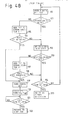
- FIGS. 4A and 4B are flow charts for describing the signal receiving and battery saving operations of the decoder 4.
- reference numerals to steps in the flow charts will be parenthesized after the corresponding phrases or clauses thereof.
- a first timer having a time duration Tl is started (103) to monitor data transit points (DTPs) (104).
- the decoder is synchronized with input data so that the leading or trailing edge of the clock pulse which is generated by the timer 412 for data writing-in, is placed at the center between DTPs (105). This step is continued until the first timer completes its time duration Tl (106).
- the last bit which is supplied at the completion timing of the first timer is stored into the decoder, and it is checked whether or not the bit is "1" (107). If it is not "1", the decoder 4 will wait one bit (108).
- a second timer having a time duration T2 is started (109) to detect the preamble signal.
- First one bit of data is written in to be checked whether or not it is "0" (111) and, if it is "0", the process will move on to the writing-in of the next bit of data (112). If it is not "0", +1 is added to an error counter Cl (115), and if the error counter Cl overflows (116), the power supply is suspended (119). If it does not overflow, the next bit of data is written in (112).
- the error counter Cl is intended for correcting any error in data. If the error counter Cl is so set as to overflow at "3" for example, it can correct two bits of error.
- a third timer with time duration T3 starts after the power supply is suspended, the process, if the duration T3 lapses, returns to step 100 (120 to 122).
- the time duration T3 corresponds to the time duration Toff in FIG. 1.
- the decoder detects the coincidence between the received preamble signal and a I/O pattern on a bit-by-bit basis. If the coincidence ceases to be detected while the timer T2 is at work, the power supply is immediately suspended (119), and the third timer (T3) is started (120). Upon completion of the time duration T3 (121), the process returns to the step 101.
- the decoder 4 will shift to the next step to receive the subscriber ID signal or call signal (123).
- the time duration T2 corresponds to the time during Ton 1 of FIG. 1B and has to be long enough to avoid erroneous operation due to noise or some other signal.
- the power supply is immediately suspended when the preamble signal ceases to be detected during the timing operation by this second timer (T2). Therefore, the period during which the power supply is actually on is much shorter than the time during T2 without sacrificing immunity to erroneous operation due to noise or the like.
- the period during which the power supply is on without any signal being received is mostly determined by the duration of stand-by to prepare for data writing-in (102) and that (Tl) of the first timer's operation (103). Accordingly, the period from the start of preamble signal detection until the power turning-off upon confirmation of the absence of the preamble signal have to be no longer than one or two bits of data unless any error has to be corrected.
- the present invention obviates the limitation of the conventional system which necessarily requires a considerable length of time until the detection of the preamble signal and which accordingly the period during which the power supply is on cannot be substantially reduced.
- the battery saver circuit of the invention can improve its battery saving efficiency. Furthermore, as it permits the period during which the preamble signal is detected to be extended, erroneous operation owing to noise or some other signal can be prevented as well.
Landscapes
- Engineering & Computer Science (AREA)
- Computer Networks & Wireless Communication (AREA)
- Signal Processing (AREA)
- Mobile Radio Communication Systems (AREA)
- Circuits Of Receivers In General (AREA)
Applications Claiming Priority (2)
| Application Number | Priority Date | Filing Date | Title |
|---|---|---|---|
| JP57090649A JPS58207733A (ja) | 1982-05-28 | 1982-05-28 | バツテリ−セ−ビング回路 |
| JP90649/82 | 1982-05-28 |
Publications (3)
| Publication Number | Publication Date |
|---|---|
| EP0095750A2 true EP0095750A2 (de) | 1983-12-07 |
| EP0095750A3 EP0095750A3 (en) | 1984-07-18 |
| EP0095750B1 EP0095750B1 (de) | 1989-03-08 |
Family
ID=14004355
Family Applications (1)
| Application Number | Title | Priority Date | Filing Date |
|---|---|---|---|
| EP83105276A Expired EP0095750B1 (de) | 1982-05-28 | 1983-05-27 | Batteriesparschaltung für einen tragbaren Radioempfänger |
Country Status (9)
| Country | Link |
|---|---|
| US (1) | US4506386A (de) |
| EP (1) | EP0095750B1 (de) |
| JP (1) | JPS58207733A (de) |
| KR (1) | KR860001461B1 (de) |
| AU (1) | AU552697B2 (de) |
| CA (1) | CA1207393A (de) |
| DE (1) | DE3379372D1 (de) |
| HK (1) | HK19291A (de) |
| SG (1) | SG8191G (de) |
Cited By (10)
| Publication number | Priority date | Publication date | Assignee | Title |
|---|---|---|---|---|
| EP0189089A1 (de) * | 1985-01-14 | 1986-07-30 | Nec Corporation | Funkrufsystem mit Fähigkeit zur gemeinsamen Informationsübertragung und Empfänger dafür |
| EP0175255A3 (en) * | 1984-09-17 | 1986-08-13 | Tateco Ab | Transmission method in staff location systems |
| EP0154288A3 (en) * | 1984-02-29 | 1987-09-16 | Nippon Telegraph And Telephone Corporation | Method of transmitting terminating call signals within a restricted duration and a base station and a portable unit for use in the same |
| US4761830A (en) * | 1986-07-23 | 1988-08-02 | Alps Electric Co., Ltd. | Communication device |
| EP0234201A3 (en) * | 1986-01-10 | 1989-04-05 | Nec Corporation | Paging receiver having battery saving circuit |
| EP0251007A3 (en) * | 1986-06-18 | 1989-08-02 | Nec Corporation | Paging receiver having a noise-immune verification circuit for disabling battery saving operation |
| EP0298575A3 (de) * | 1987-07-10 | 1990-04-18 | Koninklijke Philips Electronics N.V. | Selektivrufempfänger mit Versorgungsspannungsverteiler |
| EP0446248A4 (en) * | 1988-12-01 | 1992-09-09 | Motorola Inc. | Power conservation method and apparatus for a portion of a synchronous information signal |
| AU669395B2 (en) * | 1992-10-23 | 1996-06-06 | Nec Corporation | A method of saving power consumption in a battery operated radio pager |
| AU686936B2 (en) * | 1995-06-28 | 1998-02-12 | Samsung Electronics Co., Ltd. | Battery saving method of a paging receiver |
Families Citing this family (82)
| Publication number | Priority date | Publication date | Assignee | Title |
|---|---|---|---|---|
| JPS6027241A (ja) * | 1983-07-25 | 1985-02-12 | Nec Corp | 無線中継方式のバツテリセ−ビング方式 |
| GB8320979D0 (en) * | 1983-08-03 | 1983-09-07 | Multitone Electronics Plc | Decoding arrangements |
| JPS60170344A (ja) * | 1984-02-14 | 1985-09-03 | Matsushita Electric Ind Co Ltd | 選択呼出受信装置 |
| JPS60182229A (ja) * | 1984-02-29 | 1985-09-17 | Nippon Telegr & Teleph Corp <Ntt> | バツテリセ−ビング方式 |
| JPS6143025A (ja) * | 1984-08-07 | 1986-03-01 | Nec Corp | 無線通信方式 |
| JPS61191638U (de) * | 1985-05-20 | 1986-11-28 | ||
| JPH0683090B2 (ja) * | 1986-05-16 | 1994-10-19 | アルプス電気株式会社 | 通信装置 |
| JPS62267807A (ja) * | 1986-05-16 | 1987-11-20 | Alps Electric Co Ltd | 自動車用遠隔制御装置 |
| US4914716A (en) * | 1986-07-05 | 1990-04-03 | Ricoh Company, Ltd. | Battery-operated facsimile machine |
| US4853674A (en) * | 1986-07-21 | 1989-08-01 | Kiss Michael Z | Signalling apparatus for hearing impaired persons |
| US5204656A (en) * | 1987-07-10 | 1993-04-20 | U. S. Philips Corporation | Paging receiver with power supply divider |
| US5274843A (en) * | 1987-11-28 | 1993-12-28 | Kabushiki Kaisha Toshiba | Paging apparatus having a battery saving function |
| US5203020A (en) * | 1988-06-14 | 1993-04-13 | Kabushiki Kaisha Toshiba | Method and apparatus for reducing power consumption in a radio telecommunication apparatus |
| US4961073A (en) * | 1989-02-27 | 1990-10-02 | Motorola, Inc. | Battery saving apparatus and method providing optimum synchronization codeword detection |
| US5032835A (en) * | 1989-04-24 | 1991-07-16 | Motorola, Inc. | Out of range indication for radio receivers |
| KR910009665B1 (ko) * | 1989-05-31 | 1991-11-25 | 삼성전자 주식회사 | 무선 수신기의 전원 절약회로 및 그 제어방법 |
| JPH0832084B2 (ja) * | 1989-07-13 | 1996-03-27 | 日本電気株式会社 | 無線選択呼出し受信機 |
| US5422626A (en) * | 1989-08-15 | 1995-06-06 | Fish; David | Electrical monitoring system |
| US5049884A (en) * | 1990-10-10 | 1991-09-17 | Cincinnati Microwave, Inc. | Battery powered police radar warning receiver |
| US5231273A (en) * | 1991-04-09 | 1993-07-27 | Comtec Industries | Inventory management system |
| JPH04328919A (ja) * | 1991-04-26 | 1992-11-17 | Fujitsu Ltd | 無線呼出し信号方式 |
| US5507039A (en) * | 1991-05-10 | 1996-04-09 | Matsushita Electric Industrial Co., Ltd. | Mobile wireless apparatus with power consumption reduction circuitry |
| JP2730347B2 (ja) * | 1991-10-09 | 1998-03-25 | 松下電器産業株式会社 | 受信機の自動利得制御方法 |
| TW198782B (de) * | 1991-11-26 | 1993-01-21 | Samsung Electronics Co Ltd | |
| US5384564A (en) * | 1992-01-23 | 1995-01-24 | Keith H. Wycoff | Battery saving arrangement for selectively addressable, portable receivers |
| KR0138973B1 (ko) * | 1992-11-23 | 1998-06-15 | 죤 에이취.무어 | 클럭 주파수를 제어하여 전자 회로의 전력 소모를 최소화시키는 방법 및 장치 |
| US5440559A (en) * | 1993-11-10 | 1995-08-08 | Seiko Communications Holding N.V. | Portable wireless communication device |
| CA2135856A1 (en) * | 1993-12-10 | 1995-06-11 | Steven Peter Allen | Low power, addressable data communication device and method |
| JPH07177130A (ja) * | 1993-12-21 | 1995-07-14 | Fujitsu Ltd | エラーカウント回路 |
| CA2184286C (en) * | 1994-03-04 | 2000-06-06 | Ronald L. Bane | Remote meter reading power reduction method |
| JP2710554B2 (ja) * | 1994-04-13 | 1998-02-10 | 静岡日本電気株式会社 | 無線選択呼出し受信機のバッテリセービング方式 |
| US5650785A (en) * | 1994-11-01 | 1997-07-22 | Trimble Navigation Limited | Low power GPS receiver |
| US6359547B1 (en) * | 1994-11-15 | 2002-03-19 | William D. Denison | Electronic access control device |
| US5745860A (en) * | 1994-12-16 | 1998-04-28 | Telefonaktiebolaget Lm Ericsson | Method and system of data transmission and reception in a mobile station within a radio telecommunications system |
| WO1996038010A1 (en) * | 1995-05-23 | 1996-11-28 | Telefonaktiebolaget Lm Ericsson (Publ) | Method and apparatus for supporting delivery of short message service messages to sleeping mobile stations in a cellular communications system |
| US6064299A (en) | 1995-11-09 | 2000-05-16 | Vehicle Enhancement Systems, Inc. | Apparatus and method for data communication between heavy duty vehicle and remote data communication terminal |
| US7015800B2 (en) * | 1995-11-09 | 2006-03-21 | Vehicle Enhancement Systems Inc. | System, apparatus and methods for data communication between vehicle and remote data communication terminal, between portions of vehicle and other portions of vehicle, between two or more vehicles, and between vehicle and communications network |
| US6744352B2 (en) | 1995-11-09 | 2004-06-01 | Vehicle Enhancement Systems, Inc. | System, apparatus and methods for data communication between vehicle and remote data communication terminal, between portions of vehicle and other portions of vehicle, between two or more vehicles, and between vehicle and communications network |
| US7449993B2 (en) * | 1995-11-09 | 2008-11-11 | Vehicle Enhancement Systems, Inc. | System, apparatus and methods for data communication between vehicle and remote data communication terminal, between portions of vehicle and other portions of vehicle, between two or more vehicles, and between vehicle and communications network |
| US6111524A (en) * | 1995-11-09 | 2000-08-29 | Vehicle Enhancement Systems, Inc. | Systems and methods for identifying tractor/trailers and components thereof |
| US6005885A (en) * | 1995-12-12 | 1999-12-21 | Intermec Ip Corp. | Methodology for discontinuous radio reception utilizing embedded frame length words |
| US5793174A (en) * | 1996-09-06 | 1998-08-11 | Hunter Douglas Inc. | Electrically powered window covering assembly |
| US6396839B1 (en) * | 1997-02-12 | 2002-05-28 | Abb Automation Inc. | Remote access to electronic meters using a TCP/IP protocol suite |
| US7046682B2 (en) | 1997-02-12 | 2006-05-16 | Elster Electricity, Llc. | Network-enabled, extensible metering system |
| US6075807A (en) * | 1997-03-25 | 2000-06-13 | Intermec Ip Corp. | Windowed digital matched filter circuit for power reduction in battery-powered CDMA radios |
| US6009119A (en) * | 1997-03-25 | 1999-12-28 | Intermec Ip Corp. | Adaptive power leveling of an RF transceiver utilizing information stored in non-volatile memory |
| US6088659A (en) * | 1997-09-11 | 2000-07-11 | Abb Power T&D Company Inc. | Automated meter reading system |
| US6700902B1 (en) | 1998-10-19 | 2004-03-02 | Elster Electricity, Llc | Method and system for improving wireless data packet delivery |
| GB9920615D0 (en) * | 1999-09-02 | 1999-11-03 | Koninkl Philips Electronics Nv | Battery economising in a communications system |
| US6604038B1 (en) | 1999-11-09 | 2003-08-05 | Power Talk, Inc. | Apparatus, method, and computer program product for establishing a remote data link with a vehicle with minimal data transmission delay |
| US7040435B1 (en) * | 1999-11-17 | 2006-05-09 | Vehicle Enhancement Systems Inc. | Method for data communication between a vehicle and a remote terminal |
| US6867707B1 (en) | 2002-04-24 | 2005-03-15 | Elster Electricity, Llc | Automated on-site meter registration confirmation using a portable, wireless computing device |
| US7119713B2 (en) * | 2002-06-27 | 2006-10-10 | Elster Electricity, Llc | Dynamic self-configuring metering network |
| US20040113810A1 (en) * | 2002-06-28 | 2004-06-17 | Mason Robert T. | Data collector for an automated meter reading system |
| JP3815482B2 (ja) * | 2004-03-09 | 2006-08-30 | セイコーエプソン株式会社 | データ転送制御装置及び電子機器 |
| US7227350B2 (en) * | 2004-03-18 | 2007-06-05 | Elster Electricity, Llc | Bias technique for electric utility meter |
| US7315162B2 (en) * | 2004-03-18 | 2008-01-01 | Elster Electricity, Llc | Reducing power consumption of electrical meters |
| US7262709B2 (en) * | 2004-04-26 | 2007-08-28 | Elster Electricity, Llc | System and method for efficient configuration in a fixed network automated meter reading system |
| US7187906B2 (en) * | 2004-04-26 | 2007-03-06 | Elster Electricity, Llc | Method and system for configurable qualification and registration in a fixed network automated meter reading system |
| US7239250B2 (en) * | 2004-04-26 | 2007-07-03 | Elster Electricity, Llc | System and method for improved transmission of meter data |
| US20050251403A1 (en) * | 2004-05-10 | 2005-11-10 | Elster Electricity, Llc. | Mesh AMR network interconnecting to TCP/IP wireless mesh network |
| US20050251401A1 (en) * | 2004-05-10 | 2005-11-10 | Elster Electricity, Llc. | Mesh AMR network interconnecting to mesh Wi-Fi network |
| US7142106B2 (en) * | 2004-06-15 | 2006-11-28 | Elster Electricity, Llc | System and method of visualizing network layout and performance characteristics in a wireless network |
| US7176807B2 (en) * | 2004-09-24 | 2007-02-13 | Elster Electricity, Llc | System for automatically enforcing a demand reset in a fixed network of electricity meters |
| US7170425B2 (en) * | 2004-09-24 | 2007-01-30 | Elster Electricity, Llc | System and method for creating multiple operating territories within a meter reading system |
| US7702594B2 (en) * | 2004-09-24 | 2010-04-20 | Elster Electricity, Llc | System and method for automated configuration of meters |
| US7742430B2 (en) * | 2004-09-24 | 2010-06-22 | Elster Electricity, Llc | System for automated management of spontaneous node migration in a distributed fixed wireless network |
| US7327998B2 (en) * | 2004-12-22 | 2008-02-05 | Elster Electricity, Llc | System and method of providing a geographic view of nodes in a wireless network |
| US20060206433A1 (en) * | 2005-03-11 | 2006-09-14 | Elster Electricity, Llc. | Secure and authenticated delivery of data from an automated meter reading system |
| US7308370B2 (en) | 2005-03-22 | 2007-12-11 | Elster Electricity Llc | Using a fixed network wireless data collection system to improve utility responsiveness to power outages |
| US20060224335A1 (en) * | 2005-03-29 | 2006-10-05 | Elster Electricity, Llc | Collecting interval data from a relative time battery powered automated meter reading devices |
| US7495578B2 (en) * | 2005-09-02 | 2009-02-24 | Elster Electricity, Llc | Multipurpose interface for an automated meter reading device |
| US7308369B2 (en) * | 2005-09-28 | 2007-12-11 | Elster Electricity Llc | Ensuring automatic season change demand resets in a mesh type network of telemetry devices |
| US20070147268A1 (en) * | 2005-12-23 | 2007-06-28 | Elster Electricity, Llc | Distributing overall control of mesh AMR LAN networks to WAN interconnected collectors |
| US7545285B2 (en) * | 2006-02-16 | 2009-06-09 | Elster Electricity, Llc | Load control unit in communication with a fixed network meter reading system |
| US7427927B2 (en) | 2006-02-16 | 2008-09-23 | Elster Electricity, Llc | In-home display communicates with a fixed network meter reading system |
| US8073384B2 (en) * | 2006-12-14 | 2011-12-06 | Elster Electricity, Llc | Optimization of redundancy and throughput in an automated meter data collection system using a wireless network |
| US8320302B2 (en) * | 2007-04-20 | 2012-11-27 | Elster Electricity, Llc | Over the air microcontroller flash memory updates |
| WO2009082761A1 (en) | 2007-12-26 | 2009-07-02 | Elster Electricity, Llc. | Optimized data collection in a wireless fixed network metering system |
| US8525692B2 (en) * | 2008-06-13 | 2013-09-03 | Elster Solutions, Llc | Techniques for limiting demand from an electricity meter with an installed relay |
| US8203463B2 (en) | 2009-02-13 | 2012-06-19 | Elster Electricity Llc | Wakeup and interrogation of meter-reading devices using licensed narrowband and unlicensed wideband radio communication |
| GB2480847B (en) * | 2010-06-03 | 2014-12-10 | St Microelectronics Res & Dev | Remote testing system |
Family Cites Families (10)
| Publication number | Priority date | Publication date | Assignee | Title |
|---|---|---|---|---|
| US3824548A (en) * | 1973-01-15 | 1974-07-16 | Us Navy | Satellite communications link monitor |
| US4181893A (en) * | 1975-06-26 | 1980-01-01 | Motorola, Inc. | Battery saver for a tone coded signalling system |
| JPS5937612B2 (ja) * | 1976-04-05 | 1984-09-11 | 日本電気株式会社 | パルス検出回路 |
| JPS6013588B2 (ja) * | 1977-09-16 | 1985-04-08 | 日本電気株式会社 | 無線個別呼出受信機 |
| JPS5652440U (de) * | 1979-09-29 | 1981-05-09 | ||
| JPS593635Y2 (ja) * | 1979-09-29 | 1984-02-01 | 日本電気株式会社 | 選択呼出受信機 |
| US4419765A (en) * | 1979-10-12 | 1983-12-06 | Keith H. Wycoff | Signal absence detector |
| JPS56136050A (en) * | 1980-03-28 | 1981-10-23 | Nec Corp | Individual selective call reception system |
| KR900007702B1 (ko) * | 1980-10-01 | 1990-10-18 | 모토로라 인코포레이티드 | 통신 시스템에서의 메세이지 수신 장치 |
| JPS5792932A (en) * | 1980-12-01 | 1982-06-09 | Nec Corp | Selective calling receiver with display |
-
1982
- 1982-05-28 JP JP57090649A patent/JPS58207733A/ja active Granted
-
1983
- 1983-05-24 US US06/497,638 patent/US4506386A/en not_active Expired - Lifetime
- 1983-05-27 EP EP83105276A patent/EP0095750B1/de not_active Expired
- 1983-05-27 CA CA000429101A patent/CA1207393A/en not_active Expired
- 1983-05-27 AU AU15033/83A patent/AU552697B2/en not_active Ceased
- 1983-05-27 DE DE8383105276T patent/DE3379372D1/de not_active Expired
- 1983-05-28 KR KR1019830002373A patent/KR860001461B1/ko not_active Expired
-
1991
- 1991-02-18 SG SG81/91A patent/SG8191G/en unknown
- 1991-03-14 HK HK192/91A patent/HK19291A/en not_active IP Right Cessation
Cited By (12)
| Publication number | Priority date | Publication date | Assignee | Title |
|---|---|---|---|---|
| EP0154288A3 (en) * | 1984-02-29 | 1987-09-16 | Nippon Telegraph And Telephone Corporation | Method of transmitting terminating call signals within a restricted duration and a base station and a portable unit for use in the same |
| EP0175255A3 (en) * | 1984-09-17 | 1986-08-13 | Tateco Ab | Transmission method in staff location systems |
| EP0189089A1 (de) * | 1985-01-14 | 1986-07-30 | Nec Corporation | Funkrufsystem mit Fähigkeit zur gemeinsamen Informationsübertragung und Empfänger dafür |
| US4783654A (en) * | 1985-01-14 | 1988-11-08 | Nec Corporation | Radio paging system capable of transmitting common information and receiver therefor |
| AU591884B2 (en) * | 1985-01-14 | 1989-12-21 | Nec Corporation | Radio paging system capable of transmitting common information and receiver therefor |
| EP0234201A3 (en) * | 1986-01-10 | 1989-04-05 | Nec Corporation | Paging receiver having battery saving circuit |
| EP0251007A3 (en) * | 1986-06-18 | 1989-08-02 | Nec Corporation | Paging receiver having a noise-immune verification circuit for disabling battery saving operation |
| US4761830A (en) * | 1986-07-23 | 1988-08-02 | Alps Electric Co., Ltd. | Communication device |
| EP0298575A3 (de) * | 1987-07-10 | 1990-04-18 | Koninklijke Philips Electronics N.V. | Selektivrufempfänger mit Versorgungsspannungsverteiler |
| EP0446248A4 (en) * | 1988-12-01 | 1992-09-09 | Motorola Inc. | Power conservation method and apparatus for a portion of a synchronous information signal |
| AU669395B2 (en) * | 1992-10-23 | 1996-06-06 | Nec Corporation | A method of saving power consumption in a battery operated radio pager |
| AU686936B2 (en) * | 1995-06-28 | 1998-02-12 | Samsung Electronics Co., Ltd. | Battery saving method of a paging receiver |
Also Published As
| Publication number | Publication date |
|---|---|
| EP0095750B1 (de) | 1989-03-08 |
| SG8191G (en) | 1991-04-05 |
| DE3379372D1 (en) | 1989-04-13 |
| KR840004993A (ko) | 1984-10-31 |
| KR860001461B1 (ko) | 1986-09-25 |
| AU552697B2 (en) | 1986-06-12 |
| JPS6330818B2 (de) | 1988-06-21 |
| JPS58207733A (ja) | 1983-12-03 |
| EP0095750A3 (en) | 1984-07-18 |
| US4506386A (en) | 1985-03-19 |
| CA1207393A (en) | 1986-07-08 |
| AU1503383A (en) | 1983-12-01 |
| HK19291A (en) | 1991-03-22 |
Similar Documents
| Publication | Publication Date | Title |
|---|---|---|
| EP0095750A2 (de) | Batteriesparschaltung für einen tragbaren Radioempfänger | |
| EP0091695B1 (de) | Stromsparschaltung für einen Rufempfänger | |
| US4479125A (en) | Radio paging receiver capable of muting battery saving function | |
| US4803703A (en) | Apparatus and method for fine synchronization of a communication receiver | |
| EP0124788B1 (de) | Personenrufsystem über Funk und zugehöriger Empfänger | |
| US6633753B1 (en) | Radio communication apparatus with power consumption reduced | |
| KR880002163B1 (ko) | 수신기용 디코더 및 디코딩 방법 | |
| GB2072908A (en) | Digital radio paging communication system | |
| EP0040249A1 (de) | Personenrufempfänger und seine arbeitsweise | |
| US5187471A (en) | Radio telecommunication apparatus | |
| JPS6313432A (ja) | 選択呼出信号方式における受信装置のバツテリ・セ−ビング方法 | |
| EP0696877B1 (de) | Verfahren und Einrichtung zur Steuerung von Empfangsunterbrechungen in Funkgeräten | |
| CA1217821A (en) | Paging receiver having a plurality of test modes | |
| US5430437A (en) | Transmission and reception of pager signals without useless sampling operation | |
| JP2712868B2 (ja) | 選択呼出受信機 | |
| EP0649209B1 (de) | Stromversorgungsregelung für einen Empfänger | |
| JPS6324573B2 (de) | ||
| JP3006150B2 (ja) | 選択呼出受信機 | |
| JPS5835414B2 (ja) | 移動無線機の間欠受信方式 | |
| EP0726684A2 (de) | Intermittierende Empfangssteuereinrichtung für einen Selektivrufempfänger | |
| JPH04304041A (ja) | 選択呼出受信機 | |
| JPH05347577A (ja) | 選択呼出受信機 | |
| JPH11252607A (ja) | 無線選択呼出受信機のバッテリーセービング方法及び無線選択呼出受信機 | |
| WO1991010292A1 (en) | A method and apparatus for battery conservation in a selective call receiver | |
| JPH04349724A (ja) | 選択呼出受信機 |
Legal Events
| Date | Code | Title | Description |
|---|---|---|---|
| PUAI | Public reference made under article 153(3) epc to a published international application that has entered the european phase |
Free format text: ORIGINAL CODE: 0009012 |
|
| AK | Designated contracting states |
Designated state(s): DE FR GB NL SE |
|
| PUAL | Search report despatched |
Free format text: ORIGINAL CODE: 0009013 |
|
| AK | Designated contracting states |
Designated state(s): DE FR GB NL SE |
|
| 17P | Request for examination filed |
Effective date: 19840816 |
|
| GRAA | (expected) grant |
Free format text: ORIGINAL CODE: 0009210 |
|
| AK | Designated contracting states |
Kind code of ref document: B1 Designated state(s): DE FR GB NL SE |
|
| REF | Corresponds to: |
Ref document number: 3379372 Country of ref document: DE Date of ref document: 19890413 |
|
| ET | Fr: translation filed | ||
| PLBE | No opposition filed within time limit |
Free format text: ORIGINAL CODE: 0009261 |
|
| STAA | Information on the status of an ep patent application or granted ep patent |
Free format text: STATUS: NO OPPOSITION FILED WITHIN TIME LIMIT |
|
| 26N | No opposition filed | ||
| EAL | Se: european patent in force in sweden |
Ref document number: 83105276.6 |
|
| PGFP | Annual fee paid to national office [announced via postgrant information from national office to epo] |
Ref country code: SE Payment date: 20000508 Year of fee payment: 18 |
|
| PGFP | Annual fee paid to national office [announced via postgrant information from national office to epo] |
Ref country code: FR Payment date: 20000510 Year of fee payment: 18 |
|
| PGFP | Annual fee paid to national office [announced via postgrant information from national office to epo] |
Ref country code: DE Payment date: 20000522 Year of fee payment: 18 |
|
| PGFP | Annual fee paid to national office [announced via postgrant information from national office to epo] |
Ref country code: GB Payment date: 20000524 Year of fee payment: 18 |
|
| PGFP | Annual fee paid to national office [announced via postgrant information from national office to epo] |
Ref country code: NL Payment date: 20000531 Year of fee payment: 18 |
|
| PG25 | Lapsed in a contracting state [announced via postgrant information from national office to epo] |
Ref country code: GB Free format text: LAPSE BECAUSE OF NON-PAYMENT OF DUE FEES Effective date: 20010527 |
|
| PG25 | Lapsed in a contracting state [announced via postgrant information from national office to epo] |
Ref country code: SE Free format text: LAPSE BECAUSE OF NON-PAYMENT OF DUE FEES Effective date: 20010528 |
|
| PG25 | Lapsed in a contracting state [announced via postgrant information from national office to epo] |
Ref country code: NL Free format text: LAPSE BECAUSE OF NON-PAYMENT OF DUE FEES Effective date: 20011201 |
|
| GBPC | Gb: european patent ceased through non-payment of renewal fee |
Effective date: 20010527 |
|
| PG25 | Lapsed in a contracting state [announced via postgrant information from national office to epo] |
Ref country code: FR Free format text: LAPSE BECAUSE OF NON-PAYMENT OF DUE FEES Effective date: 20020131 |
|
| NLV4 | Nl: lapsed or anulled due to non-payment of the annual fee |
Effective date: 20011201 |
|
| PG25 | Lapsed in a contracting state [announced via postgrant information from national office to epo] |
Ref country code: DE Free format text: LAPSE BECAUSE OF NON-PAYMENT OF DUE FEES Effective date: 20020301 |