EP0095962B1 - Procédé de formage de chignons sur un stator de moteur électrique, et stator de moteur électrique ainsi réalisé - Google Patents
Procédé de formage de chignons sur un stator de moteur électrique, et stator de moteur électrique ainsi réalisé Download PDFInfo
- Publication number
- EP0095962B1 EP0095962B1 EP83400990A EP83400990A EP0095962B1 EP 0095962 B1 EP0095962 B1 EP 0095962B1 EP 83400990 A EP83400990 A EP 83400990A EP 83400990 A EP83400990 A EP 83400990A EP 0095962 B1 EP0095962 B1 EP 0095962B1
- Authority
- EP
- European Patent Office
- Prior art keywords
- stator
- matrix
- winding
- bun
- cylindrical body
- Prior art date
- Legal status (The legal status is an assumption and is not a legal conclusion. Google has not performed a legal analysis and makes no representation as to the accuracy of the status listed.)
- Expired
Links
- 238000004804 winding Methods 0.000 title claims description 19
- 238000000034 method Methods 0.000 title claims description 10
- 239000011159 matrix material Substances 0.000 claims description 19
- 238000003780 insertion Methods 0.000 claims description 5
- 230000037431 insertion Effects 0.000 claims description 5
- 210000005069 ears Anatomy 0.000 claims description 2
- 238000009740 moulding (composite fabrication) Methods 0.000 description 10
- RYGMFSIKBFXOCR-UHFFFAOYSA-N Copper Chemical compound [Cu] RYGMFSIKBFXOCR-UHFFFAOYSA-N 0.000 description 5
- 238000004519 manufacturing process Methods 0.000 description 5
- 229910052802 copper Inorganic materials 0.000 description 3
- 239000010949 copper Substances 0.000 description 3
- 238000003825 pressing Methods 0.000 description 3
- 239000004020 conductor Substances 0.000 description 2
- 238000009826 distribution Methods 0.000 description 2
- 239000012530 fluid Substances 0.000 description 2
- 238000010586 diagram Methods 0.000 description 1
- 230000009977 dual effect Effects 0.000 description 1
- 238000009434 installation Methods 0.000 description 1
- 238000012423 maintenance Methods 0.000 description 1
- 230000000717 retained effect Effects 0.000 description 1
- 238000007789 sealing Methods 0.000 description 1
- 238000007493 shaping process Methods 0.000 description 1
Images


Classifications
-
- H—ELECTRICITY
- H02—GENERATION; CONVERSION OR DISTRIBUTION OF ELECTRIC POWER
- H02K—DYNAMO-ELECTRIC MACHINES
- H02K15/00—Processes or apparatus specially adapted for manufacturing, assembling, maintaining or repairing of dynamo-electric machines
- H02K15/20—Shaping or compacting conductors or winding heads after the installation of the winding in the cores or machines; Applying fastening means on winding heads
- H02K15/24—Shaping or compacting winding heads
- H02K15/26—Applying fastening means on winding heads
-
- H—ELECTRICITY
- H02—GENERATION; CONVERSION OR DISTRIBUTION OF ELECTRIC POWER
- H02K—DYNAMO-ELECTRIC MACHINES
- H02K3/00—Details of windings
- H02K3/04—Windings characterised by the conductor shape, form or construction, e.g. with bar conductors
- H02K3/12—Windings characterised by the conductor shape, form or construction, e.g. with bar conductors arranged in slots
-
- H—ELECTRICITY
- H02—GENERATION; CONVERSION OR DISTRIBUTION OF ELECTRIC POWER
- H02K—DYNAMO-ELECTRIC MACHINES
- H02K3/00—Details of windings
- H02K3/46—Fastening of windings on the stator or rotor structure
- H02K3/50—Fastening of winding heads, equalising connectors, or connections thereto
Definitions
- the present invention relates to a p rocédéde forming winding heads on a stator of the electric motor. It also relates to an electric motor stator produced according to the present method. The invention finds application in the field of electric motors of small and medium powers.
- the stators of electric motors have two main parts.
- the first part is constituted by a cylinder pierced with a hole called stator bore and constituted by a carcass of stacked magnetic sheets.
- the second part consists of a set of coils made with conductive wires.
- the serial production of wound stator motors requires automatic assembly of these components. It is thus known a certain number of methods and machines for carrying out the introduction of the coils into the carcass of the stator and the forming of the ends of the coils also called updos.
- document presses US-A-3 593 405 are known in particular for forming presses which, for each of the buns, form an interior and form an exterior.
- stator windings are pulled from one side of the package of stator sheets so as to constitute a bun of reduced size largely freeing the stator bore for the installation of the rotor.
- this document if one reduces the quantity of conductors necessary for the realization of the windings and the number of formings, it is however necessary to form the opposite bun.
- the coil heads of this bun are stretched to the extreme to be straight, which weakens them.
- the present invention provides a remedy to the aforementioned drawbacks and particular advantages.
- the present invention which relates to a method of forming buns on an electric motor stator, of the kind consisting in introducing several coils into notches of a stator bore then in pulling them so as to produce two buns of different sizes , the bun of the smallest size being left uninserted after assembly of the windings, is characterized in that the largest bun is then formed which comprises the ends of the lead wires by force-feeding a matrix in the stator bore where it remains stuck.
- the invention also relates to a wound stator for an electric motor, the upper bun of which is formed by the method according to claim 1, characterized in that the forming die comprises a cylindrical body and a flange fixed to the cylindrical body, the lower face of which is suitable to crush, during the introduction of the matrix, the upper bun.
- FIG 2 there is shown a wound stator according to the present invention.
- the view is a sectional view along a plane passing through the axis of rotation 6 of the motor and through two diametrical notches.
- the cylindrical and metallic part of the stator is constituted by a stack of magnetic sheets 7 held by means not shown and known.
- Around the motor axis 6 is drilled a stator bore in the form of a cylinder in which the rotor of the electric motor will be placed.
- the wall of the bore is pierced with notches 8, 9 elongated along generatrices of its cylindrical shape.
- Each coil is installed in a pair of notches.
- Each of the two notches is symmetrical with the other with respect to the central axis 6 of the stator 7.
- Each coil comprises, outside the stator 7, an upper head and a lower head.
- the tangle of the coil heads on the same side is called a bun.
- the lower bun 14 is that which is disposed on the side of the stator 7 opposite to that by which the winding is introduced. It is therefore constituted by a tense distribution of all the coil heads, for example in the form of a spherical dome.
- the main characteristic of the invention is that the lower bun 14 is roughly inserted, that is to say that it is left with the tight closed shape which it has at the end of the insertion operation.
- the upper bun 13 is formed (in particular by pressing) which, in this case is of normal dimensions while the lower bun 14, gross of insertion, is of reduced dimensions .
- the reel inserting machine performs an asymmetrical distribution of the reel heads. They exceed more on the upper side (that of the bun 13) of stator 7 than on the other side (lower, that of bun 14). This makes it possible to have stator coil buns well maintained in shape and, at the same time, to reduce the manufacturing time of the motor and to reduce the amount of copper used.
- the shaping of the upper bun 13, the one with the largest dimensions is carried out by the forced introduction of a forming die 10, the fundamental shape of which comprises a cylindrical body 11 surmounted a tray 12.
- One step of the method according to the invention consists in largely freeing the opening of the bundle of coils at the upper bun to allow the introduction of the matrix 10.
- the diameter of the cylindrical body 11 is of a size such that it enters force inside the stator. Its thickness is less than the stator rotor air gap so as not to impede the rotation of the rotor when it is installed.
- the matrix 10 can serve as tight protection to the stator bore. It then makes it possible to avoid the use of an air gap tube, for example metallic, which requires the use of a part and an additional mounting operation.
- the rim 12, or plate of the matrix comes to crush the upper bun 13 formed by all of the upper heads of the coils installed in the stator.
- the rim 12 has a lower face in contact with the upper bun.
- the matrix enters by force, the lower face comes to crush the bun and also remains in position. It then performs a dual function of protection and maintenance.
- the cylindrical body 11 In the case where the forming die 10 also serves as a gap tube, the cylindrical body 11 must extend at least until the start of the lower bun 14 to cover the entire space of the stator bore.
- the cylindrical body 11 may, in particular in this case, also include a lower end, not shown in the drawing, of a shape such that it matches that of the interior of the lower bun 14, raw insertion and not formed.
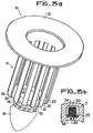
- FIG. 3a a variant of the main shape of the matrix is shown.
- the plate or rim 12 is unchanged.
- it may have the shape of a circular disc pierced with a hole in line with the stator bore.
- the cylindrical body 11 which extends at least to the bottom of the stator bore is provided with grooves 20-24 separated by bars 25-30 which each penetrate into a stator notch.
- the base of the bars 25-30 is mounted on a disc 32 terminated by a cylinder 19 concentric with the axis 6 of the motor, intended to provide an opening in the lower bun 14 not formed so that the motor shaft can come out bun.
- the pressing machine which carries the die 10 carries a tool which penetrates inside the cylindrical body 11 and the cylinder 19 and the end of which is fitted with a finger 31 , pointed, intended to open the lower bun 14 along the motor axis 6, by moving the coils apart.
- FIG. 3b there is shown a partial section of the stator 7 in a plane perpendicular to the axis 6 of the motor. Housed in the stator carcass 7, the notch 34 opens onto the cylindrical face 36 of the stator bore. Conventionally, the coil 33 is installed in its notch 34 closed by a notch bottom wedge 35. A bar 28 of the cylindrical body 11 is installed at the opening of the notch 34 on the stator bore. It thus allows an effective means to contain the coil in its notch. Thus, it is possible in many applications to eliminate the bottom shims of notches by the matrix 10 shown in FIG. 3a.
- the matrix 10, executed in this form can also cooperate with a gap tube, for example metallic, so as to achieve perfect sealing of the stator with respect to fluid flows which pass through a motor, in particular a rotor motor. drowned.
- the matrix 10, or at least its cylindrical body 11 can be lined internally with a cylindrical tube which serves as a gap tube.
- the gap tube is welded to the matrix 10 and inserted at the same time as it into the stator bore.
- the die 10 also carries the cylinder 19, it allows, by leaving an opening in the bun, to exit the motor axis for special uses where the two ends of the motor shaft are needed. This solution is also to be retained when the support bearings of the motor shaft are arranged outside of the buns.
- the disc 32 which serves as a basis for assembly and cohesion to the bars 25-30 of the cylindrical body 11 can be replaced by a spherical dome which closes the bottom of the bun 14. It can also include a cylinder 19 for opening the bun 14 for passage of the motor shaft.
- FIGS. 4 and 5 two particular forms of rim 12 are shown.
- the edges of the plate 12 are provided with folding ears 16 provided with a means 17 for fixing the ear to the edge of the carcass. stator 7.
- the rim 12 which serves to form the bun 13 comprises a skirt 18 which makes it possible to completely surround the bun. This arrangement makes it possible to limit the manufacturing operations since the embedding of the bun is carried out naturally at the end of the pressing of the die 10.
- a first advantage of these two variants is to allow mechanical protection of the upper bun 13, even of its lateral part. It thus avoids the long and costly hooping operation. This gives good dimensional control of the outside diameter of the upper bun as well as good mechanical protection of the latter.
Landscapes
- Engineering & Computer Science (AREA)
- Power Engineering (AREA)
- Manufacturing & Machinery (AREA)
- Manufacture Of Motors, Generators (AREA)
Description
- La présente invention concerne un procédéde formage de chignons sur un stator de moteur électrique. Elle concerne aussi un stator de moteur électrique réalisé selon le présent procédé. L'invention trouve application dans le domaine des moteurs électriques de petites et moyennes puissances.
- Les stators de moteurs électriques comportent deux parties principales. La première partie est constitueée par un cylindre percé d'un trou appelé alésage statorique et constituté d'une carcasse de tôles magnétiques empilées. La seconde partie est constituée par un ensemble de bobines réalisées avec des fils conducteurs. La production en série de moteurs à stators bobinés oblige à réaliser des opérations d'assemblage automatique de ces constituants. Il est ainsi connu un certain nombre de procédés et de machines pour réaliser l'introduction des bobines dans la carcasse du stator et le formage des extrémités des bobines appelées aussi chignons.
- Dans l'art antérieur, on connaît notamment du document US-A-3 593 405 des presses de formage qui font, pour chacun des chignons, un formage intérieur et un formage extérieur.
- Dans le document DE-A-2 117 213, les enroulement statoriques sont tirés d'un côté du paquet de tôles statoriques de manière à constituer un chignon de taille réduite dégageant largement l'alésage statorique pour l'installation du rotor. Selon ce document, si l'on réduit la quantité de conducteurs nécessaires à la réalisation des enroulements et le nombre de formages, il faut cependant former le chignon opposé. De plus, pour dégager largement l'ouverture dans le chignon réduit, il faut que les têtes de bobines de ce chignon soient tendues à l'extrême pour être rectilignes, ce qui les fragilise. La présente invention apporte remède aux inconvénients précités et des avantages particuliers.
- En effet la présente invention qui concerne un procédé de formage de chignons sur un stator de moteur électrique, du genre consistant à introduire plusieurs bobines dans des encoches d'un alésage statorique puis à tirer celles-ci de manière à réaliser deux chignons de tailles différentes, le chignon de taille la plus petite étant laissé brut d'insertion après montage des enroulements, est caractérisée en ce que l'on forme ensuite le chignon le plus important qui comporte les extrémités des fils de sortie par l'introduction à force d'une matrice dans l'alésage statorique où elle reste coincée.
- L'invention concerne aussi un stator bobiné pour moteur électrique dont le chignon supérieur est formé par le procédé selon la revendication 1, caractérisé en ce que la matrice de formage comprend un corps cylindrique et un rebord fixé au corps cylindrique dont la face inférieure est apte à écraser, lors de l'introduction de la matrice, le chignon supérieur.
- D'autres caractéristiques et avantages selon la présente invention seront dégagés à l'aide de la description et des figures annexées qui sont:
- - la figure 1 : un schéma d'une bobine,
- - la figure 2 : un coupe d'un stator après l'opération de formage selon la présente invention,
- - les figures 3a et 3b : un dessin en perspective d'une première variante d'une matrice selon l'invention,
- - la figure 4 : un dessin en perspective d'une seconde variante d'une matrice selon l'invention,
- - la figure 5 : un dessin en perspective d(une troisième variante d'une matrice selon l'invention, A la figure 1, on a représenté une bobine complète prête à être installée dans les encoches de la carcasse statorique. Cette bobine comporte un enroulement 1 constiuté d'un certain nombre de spires de fils de cuivre émaillé. Avant son insertion dans le stator du moteur, la bobine est maintenue en forme par deux manchons 2 et 3 répartis de part et d'autre du futur axe de rotation 61 du moteur. Ces manchons 2 et 3 protègent les fils de cuivre, une fois l'ensemble des bobines installé dans les encoches du stator. D'autre part, deux conducteurs d'accès 4, 5 sortent de la bobine et sont disponibles pour l'amenée et la sortie du courant dans la bobine.
- A la figure 2, on a représenté un stator bobiné selon la présente invention. La vue, est une vue en coupe selon un plan passant par l'axe de rotation 6 du moteur et par deux encoches diamétrales. La partie cylindrique et métallique du stator est constituée par un empilement de tôles magnétiques 7 maintenues par un moyen non représenté et connu. Autour de l'axe moteur 6 est percé un alésage statorique en forme de cylindre dans lequel viendra se placer le rotor du moteur électrique. La paroi de l'alésage est percé d'encoches 8, 9 allongées le long de génératrices de sa forme cylindrique. Chaque bobine est installée dans une paire d'encoches. Chacune des deux encoches est symétrique de l'autre par rapport à l'axe 6 central du stator 7. A la fabrication du moteur, l'ensemble des bobines est placé dans une machine à insérer le bobinage dans l'alésage statorique.
- Chaque bobine comporte, hors du stator 7, une tête supérieure et une tête inférieure. Une fois l'ensemble des bobines installées, on appelle chignon l'enchevêtrement des têtes de bobines d'un même côté. A la figure 2, on remarque un chignon supérieur 13 et un chignon inférieur 14. Le chignon inférieur 14 est celui qui est disposé du côté du stator 7 opposé à celui par lequel le bobinage est introduit. Il est donc constitué par une répartition tendue de toutes les têtes de bobines, par exemple en forme de coupole sphérique. La caractéristique principale de l'invention est que le chignon inférieur 14 est brut d'insertion, c'est à dire qu'on lui laisse la forme fermée tendue qu'il a à la fin de l'opération d'insertion.
- Selon une autre caractéristique du procédé de l'invention, on réalise le formage (notamment par pressage) du chignon supérieur 13. qui, dans ce cas est de dimensions normales tandis que le chignon inférieur 14, brut d'insertion, est de dimensions réduites. La machine à insérer les bobines réalise une répartition asymétrique des têtes de bobines. Elles dépassent plus du coté supérieur (celui du chignon 13) du stator 7 que de l'autre coté (inférieur, celui de chignon 14). Ceci permet d'avoir des chignons de bobines statoriques bien maintenues en forme et, en même temps, de réduire le temps de fabrication du moteur et de réduire la quantité de cuivre utilisé. Ces deux derniers avantages sont considérables quand le moteur est fabriqué en grandes séries notamment sur des chaînes de fabrication automatique. L'un des résultats notables est la diminution du coût de fabrication.
- Selon une autre caractéristique de l'invention, le formage du chignon supérieur 13, celui dont les dimensions sont les plus importantes, est réalisé par l'introduction à force d'une matrice de formage 10 dont la forme fondamentale comprend un corps cylindrique 11 surmonté d'un plateau 12.
- Une étape du procédé selon l'invention constiste à dégager largement l'ouverture du faisceau de bobines au chignon supérieur pour permettre l'introduction de la matrice 10. Le diamètre du corps cylindrique 11 est d'une dimension telle qu'il entre à force à l'intérieur du stator. Son épaisseur est inférieure à l'entrefer statorrotor pour ne pas gêner la rotation du rotor quand celui-ci est installé. Quand le moteur est peu ou pas soumis à des contraintes internes, contrairement au cas des moteurs à rotor noyé qui transitent de forts débits de fluides, alors la matrice 10 peut servir de protection étanche à l'alésage statorique. Elle permet alors d'éviter l'usage d'un tube d'entrefer par exemple métallique qui nécessite l'usage d'une pièce et d'une opération de montage supplémentaire. Le rebord 12, ou plateau de la matrice, vient écraser le chignon supérieur 13 constitué par l'ensemble de toutes les têtes supérieures des bobines installées dans le stator.
- Le rebord 12 comporte une face inférieure en contact avec le chignon supérieur. Quand, par le moyen d'une presse, la matrice entre à force, la face inférieure vient écraser le chignon et reste aussi en position. Elle assure alors une double fonction de protection et de maintien. mécanique du chignon 13.
- Enfin le chignon inférieur 14 des bobines est libre de formage.
- Dans le cas où la matrice 10 de formage sert aussi de tube d'entrefer, le corps cylindrique 11 doit s'étendre au moins jusqu'au début du chignon inférieur 14 pour couvrir tout l'espace de l'alésage statorique. Le corps cylindrique 11 peut, notamment dans ce cas, comporter aussi une extrémité basse, non représentée au dessin, d'une forme telle qu'elle épouse celle intérieure du chignon inférieur 14, brut d'insertion et non formé.
- A la figure 3a, on a représenté une variante de la forme principale de la matrice. Le plateau ou rebord 12 est inchangé. Par exemple, comme représenté ici, il peut avoir la forme d'un disque circulaire percé d'un trou au droit de l'alésage statorique. Le corps cylindrique 11 qui s'étend au moins jusqu'au fond de l'alésage statorique est purvu de rainures 20-24 séparées par des barres 25-30 qui pénètrent chacune dans une encoche statorique. La base des barres 25-30 est montée sur un disque 32 terminé par un cylindre 19 concentrique à l'axe 6 du moteur, destiné à ménager une ouverture dans le chignon 14 inférieur non formé de façon à ce que l'arbre moteur puisse ressortir du chignon. Pour celà, au pressage de la matrice 10 pour le formage la machine de pressage qui porte la matrice 10 porte un outil qui pénètre à l'intérieur du corps cylindrique 11 et du cylindre 19 et dont l'extrémité est garnie d'un doigt 31, pointu, destiné à ouvrir le chignon 14 inférieur le long de l'axe 6 moteur, en écartant les bobines.
- Cette variante permet que la matrice 10 n'occupe pas l'entrefer rotor-stator. Elle permet aussi de fournir un moyen pour contenir des bobines dans leurs encoches puisque les barres 25-30 viennent boucher les encoches statoriques. A la figure 3b on a représenté une coupe partielle du stator 7 dans un plan perpendiculaire à l'axe 6 du moteur. Ménagée dans la carcasse statorique 7, l'encoche 34 débouche sur la face cylindrique 36 de l'alésage statorique. Classiquement, la bobine 33 est installée dans son encoche 34 fermée par une cale de fond d'encoche 35. Une barre 28 du corps cylindrique 11 est installée à l'ouverture de l'encoche 34 sur l'alésage statorique. Elle permet ainsi un moyen efficace pour contenir la bobine dans son encoche. Ainsi, il est possible dans de nombreuses applications de supprimer les cales de fond d'encoches par la matrice 10 représentée figure 3a.
- D'autre part, la matrice 10, exécutée sous cette forme, peut aussi coopérer avec un tube d'entrefer, par exemple métallique, de façon à réaliser une étanchéité parfaite du stator par rapport à des flux fluides qui traversent un moteur notamment à rotor noyé. Pour celà, la matrice 10, ou du moins son corps cylindrique 11, peut être doublée intérieurement d'un tube cylindrique qui sert de tube d'entrefer. Dans un exemple de réalisation, le tube d'entrefer est soudé à la matrice 10 et inséré en même temps qu'elle dans l'alésage statorique. Enfin, quand la matrice 10 porte aussi le cylindre 19, elle permet, en ménageant une ouverture dans le chignon, de sortir l'axe moteur pour des utilisations spéciales où l'on a besoin des deux extrémités de l'arbre moteur. Cette solution est à retenir aussi quand les paliers de support de l'arbre moteur sont disposés hors des chignons. Le disque 32 qui sert de base d'assemblage et de cohésion aux barres 25-30 du corps cylindrique 11 peut être remplacé par une coupole sphérique qui ferme le fond du chignon 14. Elle peut comporter aussi un cylindre 19 d'ouverture du chignon 14 pour passage de l'arbre moteur.
- Aux figures 4 et 5 on a représenté deux formes particulières de rebord 12. A la figure 4, les bords du plateau 12 sont munis d'oreilles rabattables 16 munies d'un moyen de fixation 17 de l'oreille sur le bord de la carcasse statorique 7.
- A la figure 5, le rebord 12 qui sert à former le chignon 13, comporte une jupe 18 qui permet d'entourer complétement le chignon. Cette disposition permet de limiter les opérations de fabrication puisque l'englobement du chignon est réalisé naturellement à la fin du pressage de la matrice 10.
- Un premier avantage de ces deux variantes est de permettre une protection mécanique du chignon supérieur 13, même de sa partie latérale. Elle évite ainsi l'opération de frettage longue et coûteuse. On obtient ainsi une bonne maîtrise dimensionnelle du diamètre extérieur du chignon supérieur ainsi qu'une bonne protection mécanique de celui-ci.
Claims (7)
Applications Claiming Priority (2)
| Application Number | Priority Date | Filing Date | Title |
|---|---|---|---|
| FR8209254 | 1982-05-27 | ||
| FR8209254A FR2527856A1 (fr) | 1982-05-27 | 1982-05-27 | Procede de formage de chignons sur un stator de moteur electrique, et stator de moteur electrique ainsi realise |
Publications (2)
| Publication Number | Publication Date |
|---|---|
| EP0095962A1 EP0095962A1 (fr) | 1983-12-07 |
| EP0095962B1 true EP0095962B1 (fr) | 1986-06-11 |
Family
ID=9274396
Family Applications (1)
| Application Number | Title | Priority Date | Filing Date |
|---|---|---|---|
| EP83400990A Expired EP0095962B1 (fr) | 1982-05-27 | 1983-05-17 | Procédé de formage de chignons sur un stator de moteur électrique, et stator de moteur électrique ainsi réalisé |
Country Status (3)
| Country | Link |
|---|---|
| EP (1) | EP0095962B1 (fr) |
| DE (1) | DE3364058D1 (fr) |
| FR (1) | FR2527856A1 (fr) |
Families Citing this family (6)
| Publication number | Priority date | Publication date | Assignee | Title |
|---|---|---|---|---|
| US4484096A (en) * | 1983-08-11 | 1984-11-20 | Black & Decker Inc. | Field subassembly for an electric motor |
| DE4234145C1 (de) * | 1992-10-09 | 1994-02-03 | Wolfgang Hill | Mehrphasige elektrische Maschinem mit vorgefertigten Leitersträngen und Verfahren zu ihrer Herstellung |
| JPH07288941A (ja) * | 1994-04-12 | 1995-10-31 | Mitsubishi Electric Corp | 電動機 |
| EP2226923B1 (fr) | 2009-03-03 | 2015-06-10 | GE Energy Power Conversion Technology Limited | Bobines |
| US9337695B2 (en) | 2010-02-22 | 2016-05-10 | GE Energy Conversion Technology LTD. | Single-layer coil with one bent endwinding and one straight endwinding |
| FR3121296A1 (fr) * | 2021-03-23 | 2022-09-30 | Liebherr-Aerospace Toulouse Sas | Procédé d’installation de groupes de bobine dans une machine électrique |
Family Cites Families (6)
| Publication number | Priority date | Publication date | Assignee | Title |
|---|---|---|---|---|
| US3593405A (en) * | 1969-09-05 | 1971-07-20 | Gen Electric | Apparatus for forming winding end turns |
| DE2039114C3 (de) * | 1970-08-06 | 1974-11-14 | Licentia Patent-Verwaltungs-Gmbh, 6000 Frankfurt | Kühlungseinrichtung für einen eine Heizungswasser-Umwälzpumpe antreibenden Elektromotor und Verfahren zur Herstellung einer Isolierschicht |
| DE2117213A1 (de) * | 1971-04-08 | 1972-10-26 | Licentia Patent-Verwaltungs-Gmbh, 6000 Frankfurt | Elektromotor mit Innenläufer |
| JPS4954801A (fr) * | 1972-09-27 | 1974-05-28 | ||
| US3984712A (en) * | 1974-11-11 | 1976-10-05 | Industra Products, Inc. | End turn shield and winding connector |
| US4227108A (en) * | 1978-04-24 | 1980-10-07 | Tokyo Shibaura Electric Co., Ltd. | Glass compound layer for mechanical and thermal protection of a laminated iron core rotary electromachine |
-
1982
- 1982-05-27 FR FR8209254A patent/FR2527856A1/fr active Granted
-
1983
- 1983-05-17 EP EP83400990A patent/EP0095962B1/fr not_active Expired
- 1983-05-17 DE DE8383400990T patent/DE3364058D1/de not_active Expired
Also Published As
| Publication number | Publication date |
|---|---|
| FR2527856B1 (fr) | 1984-12-14 |
| FR2527856A1 (fr) | 1983-12-02 |
| EP0095962A1 (fr) | 1983-12-07 |
| DE3364058D1 (en) | 1986-07-17 |
Similar Documents
| Publication | Publication Date | Title |
|---|---|---|
| FR2556146A1 (fr) | Dispositif de montage et d'isolation de conducteurs sur les rotors de machines tournantes electriques | |
| FR2613884A1 (fr) | Machine electrique comprenant un paquet de toles supportant un enroulement, et procede pour sa fabrication | |
| FR2483702A1 (fr) | Procede et dispositif pour la realisation du bobinage d'un stator d'alternateur de petite puissance | |
| EP0157670B1 (fr) | Transformateur et son procédé de fabrication | |
| FR3144719A1 (fr) | Stator pour machine électrique à flux axial et procédé d’obtention d’un tel stator | |
| EP0095962A1 (fr) | Procédé de formage de chignons sur un stator de moteur électrique, et stator de moteur électrique ainsi réalisé | |
| FR3082373A1 (fr) | Stator de machine electrique tournante | |
| FR2745442A1 (fr) | Procede de fabrication d'une partie tournante bobinee de machine electrique | |
| EP3804085A1 (fr) | Stator de machine electrique tournante | |
| EP3534500B1 (fr) | Rotor ou stator bobine et procede de fabrication | |
| EP4128485A1 (fr) | Dispositif de connexion pour stator | |
| EP3170246A1 (fr) | Procede de realisation d'un stator bobine de machine electrique tournante | |
| FR2711456A1 (fr) | Machine électrique tournante et son procédé de fabrication. | |
| WO2007125234A1 (fr) | Procédé de montage d'un enroulement d'un bobinage de stator dans un paquet de tôles | |
| EP4311086A1 (fr) | Dispositif de fabrication d'un empilement de tôles | |
| FR3088152A1 (fr) | Machine electrique tournante et procede de fabrication d'une telle machine | |
| FR2584246A1 (fr) | Disposition de fils de bobinage dans les encoches d'un induit d'une machine a courant continu | |
| FR2801142A1 (fr) | Tole de machine tournante electrique a elements rapportes | |
| EP0990295B2 (fr) | Procede de bobinage et bobines pour machine electrique tournantes | |
| EP0692861A1 (fr) | Paquet de tÔles découpées pour la fabrication d'un rotor | |
| EP0451065B1 (fr) | Procédé et dispositif pour l'isolation des têtes de bobinage électrique | |
| FR2784496A1 (fr) | Circuit magnetique pour transformateur d'energie electrique | |
| BE555834A (fr) | ||
| FR3080500A1 (fr) | Rotor de machine electrique tournante | |
| FR2846806A1 (fr) | Procede de fabrication de conducteurs electriques en forme d'epingles en u, dispositif pour la mise en oeuvre de ce procede et conducteurs ainsi obtenus |
Legal Events
| Date | Code | Title | Description |
|---|---|---|---|
| PUAI | Public reference made under article 153(3) epc to a published international application that has entered the european phase |
Free format text: ORIGINAL CODE: 0009012 |
|
| AK | Designated contracting states |
Designated state(s): BE CH DE GB IT LI NL |
|
| 17P | Request for examination filed |
Effective date: 19831227 |
|
| ITF | It: translation for a ep patent filed | ||
| RAP1 | Party data changed (applicant data changed or rights of an application transferred) |
Owner name: POMPES SALMSON SOCIETE ANONYME A DIRECTOIRE DITE: |
|
| GRAA | (expected) grant |
Free format text: ORIGINAL CODE: 0009210 |
|
| AK | Designated contracting states |
Kind code of ref document: B1 Designated state(s): BE CH DE GB IT LI NL |
|
| REF | Corresponds to: |
Ref document number: 3364058 Country of ref document: DE Date of ref document: 19860717 |
|
| PLBE | No opposition filed within time limit |
Free format text: ORIGINAL CODE: 0009261 |
|
| STAA | Information on the status of an ep patent application or granted ep patent |
Free format text: STATUS: NO OPPOSITION FILED WITHIN TIME LIMIT |
|
| 26N | No opposition filed | ||
| PGFP | Annual fee paid to national office [announced via postgrant information from national office to epo] |
Ref country code: BE Payment date: 19940516 Year of fee payment: 12 |
|
| ITTA | It: last paid annual fee | ||
| PGFP | Annual fee paid to national office [announced via postgrant information from national office to epo] |
Ref country code: NL Payment date: 19940531 Year of fee payment: 12 |
|
| PGFP | Annual fee paid to national office [announced via postgrant information from national office to epo] |
Ref country code: CH Payment date: 19940822 Year of fee payment: 12 |
|
| PG25 | Lapsed in a contracting state [announced via postgrant information from national office to epo] |
Ref country code: LI Effective date: 19950531 Ref country code: CH Effective date: 19950531 Ref country code: BE Effective date: 19950531 |
|
| BERE | Be: lapsed |
Owner name: POMPES SALMSON Effective date: 19950531 |
|
| PG25 | Lapsed in a contracting state [announced via postgrant information from national office to epo] |
Ref country code: NL Effective date: 19951201 |
|
| REG | Reference to a national code |
Ref country code: CH Ref legal event code: PL |
|
| NLV4 | Nl: lapsed or anulled due to non-payment of the annual fee |
Effective date: 19951201 |
|
| REG | Reference to a national code |
Ref country code: GB Ref legal event code: IF02 |
|
| PGFP | Annual fee paid to national office [announced via postgrant information from national office to epo] |
Ref country code: GB Payment date: 20020517 Year of fee payment: 20 |
|
| PGFP | Annual fee paid to national office [announced via postgrant information from national office to epo] |
Ref country code: DE Payment date: 20020607 Year of fee payment: 20 |
|
| PG25 | Lapsed in a contracting state [announced via postgrant information from national office to epo] |
Ref country code: GB Free format text: LAPSE BECAUSE OF EXPIRATION OF PROTECTION Effective date: 20030516 |
|
| REG | Reference to a national code |
Ref country code: GB Ref legal event code: PE20 |