EP0096291A2 - Dispositif pour coupler les arbres de prise d'au moins deux systèmes de transport interchangeables, juxtaposés, dans une machine de développement - Google Patents
Dispositif pour coupler les arbres de prise d'au moins deux systèmes de transport interchangeables, juxtaposés, dans une machine de développement Download PDFInfo
- Publication number
- EP0096291A2 EP0096291A2 EP83105140A EP83105140A EP0096291A2 EP 0096291 A2 EP0096291 A2 EP 0096291A2 EP 83105140 A EP83105140 A EP 83105140A EP 83105140 A EP83105140 A EP 83105140A EP 0096291 A2 EP0096291 A2 EP 0096291A2
- Authority
- EP
- European Patent Office
- Prior art keywords
- drive
- shaft
- shaft piece
- rack
- coupling
- Prior art date
- Legal status (The legal status is an assumption and is not a legal conclusion. Google has not performed a legal analysis and makes no representation as to the accuracy of the status listed.)
- Withdrawn
Links
- 230000008878 coupling Effects 0.000 title claims abstract description 27
- 238000010168 coupling process Methods 0.000 title claims abstract description 27
- 238000005859 coupling reaction Methods 0.000 title claims abstract description 27
- 238000006073 displacement reaction Methods 0.000 claims 1
- 238000002347 injection Methods 0.000 claims 1
- 239000007924 injection Substances 0.000 claims 1
- 230000035945 sensitivity Effects 0.000 description 4
- 230000013011 mating Effects 0.000 description 2
- 238000000034 method Methods 0.000 description 2
- WYTGDNHDOZPMIW-RCBQFDQVSA-N alstonine Natural products C1=CC2=C3C=CC=CC3=NC2=C2N1C[C@H]1[C@H](C)OC=C(C(=O)OC)[C@H]1C2 WYTGDNHDOZPMIW-RCBQFDQVSA-N 0.000 description 1
- 238000006243 chemical reaction Methods 0.000 description 1
- 239000003814 drug Substances 0.000 description 1
- 238000005516 engineering process Methods 0.000 description 1
- 239000000463 material Substances 0.000 description 1
Images


Classifications
-
- G—PHYSICS
- G03—PHOTOGRAPHY; CINEMATOGRAPHY; ANALOGOUS TECHNIQUES USING WAVES OTHER THAN OPTICAL WAVES; ELECTROGRAPHY; HOLOGRAPHY
- G03D—APPARATUS FOR PROCESSING EXPOSED PHOTOGRAPHIC MATERIALS; ACCESSORIES THEREFOR
- G03D3/00—Liquid processing apparatus involving immersion; Washing apparatus involving immersion
- G03D3/08—Liquid processing apparatus involving immersion; Washing apparatus involving immersion having progressive mechanical movement of exposed material
- G03D3/13—Liquid processing apparatus involving immersion; Washing apparatus involving immersion having progressive mechanical movement of exposed material for long films or prints in the shape of strips, e.g. fed by roller assembly
Definitions
- the invention relates to a device for coupling drive shafts of at least two interchangeable transport devices for films or pieces of film to be arranged next to one another in a developing machine.
- a developing device in which a roll film of a certain size can be treated.
- This known device has a series of treatment tanks arranged one behind the other, into which the racks with a width corresponding to the film width are inserted.
- a device drive is provided for each rack, which is connected to a central drive.
- the width of these racks corresponds to the largest width of roll films (1 0 5 mm), which is common on the market.
- recording motion pictures 35 mm films or 16 mm films.
- Other film widths such as 100, 90 and 70 mm, are also used in X-rays today.
- film strips of 8, 16 and 35 mm are used.
- the object of the invention is therefore to provide coupling elements of the type in question, which allow the racks to be introduced in a substantially perpendicular direction to the axes of the drive shafts and enable easy coupling of adjacent drive shafts.
- a clutch which can be operated is achieved, which enables a play-free, tolerance-compensating and even lockable connection of the drive units to one another.
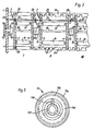
- Fig. 1 denotes a treatment tank of a developing device, in which an insert 2 is provided for conveying the films or pieces of film through the treatment tank 1.
- the insert or the rack 2 is, as especially from-Fig. 2 can be seen, made up of two side walls 3 and 4, which are held in a known manner at a fixed distance from one another by studs, not shown.
- corresponding guide grooves 5 and 6 are formed with a shape corresponding to the film web.
- the film path is essentially U-shaped, but is curved over the entire length of the legs in the form of a serpentine line, as is particularly evident from FIG. 1. At the upper end, the groove runs in and out horizontally.
- Conveyor rollers 7 and 8 are arranged at the turning points of the curved film web.
- the conveyor rollers 7 are rotatably mounted in bores of the side parts 3, 4 and via gears 9 located outside the side part 3 on the shaft of the rollers 7, each connected to a central drive wheel 10, which meshes constantly with similar gears, so that all gears 9 on the Gears 10 with an uppermost main drive wheel 11 are engaged.
- a rack 2 is inserted into the tank 1, all the gears 9 and thus the conveyor rollers 7 are then connected to a common drive in a known manner.
- the outer conveyor rollers 8 are slidably mounted in slots 12 of the side parts 3, 4 in the direction of the corresponding inner conveyor rollers 7.
- a wheel 13 is fastened to the shaft of the rollers 8, with four such wheels 13, the conveyor rollers 7 of which are driven by a common drive gear 10, being spanned by an elastic, endless belt 14.
- the rollers 8 are each held in contact with the corresponding roller 7 by this belt 14.
- FIG. 2 also shows a device drive 15 in the form of a gearwheel, which is arranged outside the treatment container 1, connected to a drive belt and mounted on a shaft 16 which leads through the tank wall and carries a gearwheel 17 on the inside.
- the toothed wheel 17 meshes with the main drive wheel 11 of the rack which is initially arranged on the drive side and which is double-wide and, as already mentioned above, also engages with the uppermost drive wheel 10.
- the main drive wheel 11 is arranged on a shaft 18 which is guided through the two side parts 3 and 4.
- On the main drive gear 11 k upplung may be placed a coupling element 19 in the form of a curved teeth.
- a mating coupling element in the form of a gear wheel 20 is arranged, which can have the shape of a screw cylinder head.
- the web 19 of a main drive wheel can easily be inserted into the slot 20a of the mating coupling element 20, as can be seen from FIG. 3.
- a positioning pin 21 is provided in each rack, which is also guided through the two side parts 3 and 4 and, when the rack is inserted, its end is inserted into a bore 22 by means of a spring (not shown) .
- a button 23 is attached, in which a bore 22 'is provided in the same orientation as the bore 22 in the treatment tank 1.
- the centering pin of the adjacent rack in FIG. 3, for example the middle rack, can thus be inserted into the bore 22 'in the button 23 of the centering pin 21 in the rack 2 closest to the tank wall 1.
- cross bars 24 are also shown, which extend transversely to the transport direction of the film between two side walls of the treatment tank 1.
- the number and the distances to the side wall of the tank 1 are determined depending on the desired rack types. For example, racks with six different widths can be used on the first transport track I, only one groove 25 being provided for the side part 3 which is closest to the tank wall, and six adjacent grooves 25 are provided for the other side part 4, depending on the rack width.
- the further grooves 25 are also shaped to allow different combinations of different widths.
- the drive shaft 18 is longer on the side carrying the drive wheel 11 and has approximately the length of a coupling element 19.
- the gear 11 is attached approximately in the middle of the protruding shaft piece 18a.
- a groove 18b is formed around the jacket.
- the coupling element 19 consists essentially of a cylindrical sleeve 19a with a continuous internal toothing 19b.
- a handle 19c is formed on the outside of the cylinder jacket.
- Formed in the interior of the sleeve 19a is an annular disk 19d which interrupts the toothing 19b and from which spring arms 19e extend, which have locking projections 19f which extend inwards in the radial direction.
- FIG. 4 a shows the coupled state of two adjacent racks, the coupling element 19 with the smaller part of the internal toothing being pushed onto the driven gear 20 of one rack and the drive via the larger part of the internal toothing 19b onto the driving wheel 11 of the next Racks transmits.
- the projections 19f of the resilient arms 19e engage in the groove 18b of the shaft piece 18a of the next rack.
- the coupling element 19 only needs to be shifted towards the next rack, that is to say to the right in FIG. 4 a).
- the projections 19f come out of engagement with the groove 18b and they slide along the circumference of the shaft piece 18a until the coupling element abuts the side wall 3 of the next rack.
- the coupling element is still guided on the gear 11, which runs in the internal toothing 19b. With this shift, the driven wheel 20 is released, with which one of the two racks, provided that it is also free on its other side, can now be removed from the device.
- the coupling element 19 only needs to be pushed to the left over the gearwheel 20 until the projections 19f engage in the NJ t 18b.
- the first rack is now always inserted into the closest 25 to the tank wall carrying the drive, as is indicated by transport path I.
- a rack of a different width is then inserted into the transport path II, the coupling element 19 on the main drive wheel 11 of the second rack being pushed onto the driven wheel 20 of the first rack in the manner described above.
- the centering pin 21 of the second rack is inserted into the bore 22 'of the centering pin of the first rack, whereby both racks are fixed in their alignment.
- a third rack can be attached to the second rack on the transport path III.
- the racks of the same width are arranged in the same way in the subsequent treatment containers.
- the films or film pieces can then be developed in a known manner.
- rack sizes can also be provided with regard to the dwell time.
- racks of different widths and different sizes can also be combined with one another in order to be able to provide the different treatment processes for the respective material.
- the rack conversions in a processor can be carried out quickly and easily.
Landscapes
- Physics & Mathematics (AREA)
- General Physics & Mathematics (AREA)
- Photographic Processing Devices Using Wet Methods (AREA)
- Mechanical Operated Clutches (AREA)
- Photographic Developing Apparatuses (AREA)
Applications Claiming Priority (2)
| Application Number | Priority Date | Filing Date | Title |
|---|---|---|---|
| DE19823220236 DE3220236A1 (de) | 1982-05-28 | 1982-05-28 | Einrichtung zum koppeln der antriebswellen von mindestens zwei nebeneinander anzuordnenden, auswechselbaren transportvorrichtungen in einer entwicklungsmaschine |
| DE3220236 | 1982-05-28 |
Publications (2)
| Publication Number | Publication Date |
|---|---|
| EP0096291A2 true EP0096291A2 (fr) | 1983-12-21 |
| EP0096291A3 EP0096291A3 (fr) | 1986-03-12 |
Family
ID=6164810
Family Applications (1)
| Application Number | Title | Priority Date | Filing Date |
|---|---|---|---|
| EP83105140A Withdrawn EP0096291A3 (fr) | 1982-05-28 | 1983-05-25 | Dispositif pour coupler les arbres de prise d'au moins deux systèmes de transport interchangeables, juxtaposés, dans une machine de développement |
Country Status (5)
| Country | Link |
|---|---|
| US (1) | US4514071A (fr) |
| EP (1) | EP0096291A3 (fr) |
| JP (1) | JPS58217824A (fr) |
| DE (1) | DE3220236A1 (fr) |
| DK (1) | DK159178C (fr) |
Cited By (1)
| Publication number | Priority date | Publication date | Assignee | Title |
|---|---|---|---|---|
| DE19625962C1 (de) * | 1996-06-28 | 1997-11-20 | Agfa Gevaert Ag | Vorrichtung zum Behandeln von fotografischen Schichtträgern |
Families Citing this family (4)
| Publication number | Priority date | Publication date | Assignee | Title |
|---|---|---|---|---|
| JP3112218B2 (ja) * | 1993-04-27 | 2000-11-27 | 富士写真フイルム株式会社 | 感光材料処理装置 |
| US8245551B2 (en) | 2008-04-24 | 2012-08-21 | Crown Packaging Technology, Inc. | Adjustable transfer assembly for container manufacturing process |
| US8464567B2 (en) * | 2008-04-24 | 2013-06-18 | Crown Packaging Technology, Inc. | Distributed drives for a multi-stage can necking machine |
| US10683900B2 (en) * | 2017-03-29 | 2020-06-16 | Pratt & Whitney Canada Corp. | Clutch device for gas turbine engines |
Family Cites Families (7)
| Publication number | Priority date | Publication date | Assignee | Title |
|---|---|---|---|---|
| US2894775A (en) * | 1952-03-20 | 1959-07-14 | Hoe & Co R | Rotary shaft clutch |
| US2952143A (en) * | 1958-12-01 | 1960-09-13 | Us Rubber Co | Flexible shaft couplings |
| US2918809A (en) * | 1959-02-26 | 1959-12-29 | Sier Bath Gear And Pump Co Inc | Flexible coupling for shafts |
| US3243973A (en) * | 1963-01-30 | 1966-04-05 | Drafto Corp | Flexible gear couplings |
| US3588154A (en) * | 1968-10-29 | 1971-06-28 | Bendix Corp | Torque coupling device |
| US3672290A (en) * | 1969-10-13 | 1972-06-27 | George W Duesler | Film processing apparatus |
| DE3119318C2 (de) * | 1981-05-15 | 1985-07-25 | Agfa-Gevaert Ag, 5090 Leverkusen | Entwicklungsvorrichtung für Filme oder Filmstücke |
-
1982
- 1982-05-28 DE DE19823220236 patent/DE3220236A1/de not_active Withdrawn
-
1983
- 1983-05-12 JP JP58081846A patent/JPS58217824A/ja active Granted
- 1983-05-20 US US06/496,448 patent/US4514071A/en not_active Expired - Fee Related
- 1983-05-25 EP EP83105140A patent/EP0096291A3/fr not_active Withdrawn
- 1983-05-27 DK DK240383A patent/DK159178C/da active
Cited By (1)
| Publication number | Priority date | Publication date | Assignee | Title |
|---|---|---|---|---|
| DE19625962C1 (de) * | 1996-06-28 | 1997-11-20 | Agfa Gevaert Ag | Vorrichtung zum Behandeln von fotografischen Schichtträgern |
Also Published As
| Publication number | Publication date |
|---|---|
| DK240383D0 (da) | 1983-05-27 |
| US4514071A (en) | 1985-04-30 |
| JPS58217824A (ja) | 1983-12-17 |
| EP0096291A3 (fr) | 1986-03-12 |
| JPH0148540B2 (fr) | 1989-10-19 |
| DK240383A (da) | 1983-11-29 |
| DK159178B (da) | 1990-09-10 |
| DK159178C (da) | 1991-02-11 |
| DE3220236A1 (de) | 1983-12-01 |
Similar Documents
| Publication | Publication Date | Title |
|---|---|---|
| DE3119318C2 (de) | Entwicklungsvorrichtung für Filme oder Filmstücke | |
| DE3876532T2 (de) | Vorrichtung zur wahl einer vorbestimmten anzahl von gefaessen, die teilweise ineinander gesteckt werden und auf diese weise eine einzige gefaesspackung bilden. | |
| DE2610904A1 (de) | Foerdereinrichtung fuer stueckgueter, insbesondere bretter | |
| DE2164215C3 (de) | Vorrichtung zum Transportieren eines bahnförmigen randgelochten Materials | |
| DE2749225A1 (de) | Vorrichtung zum in querrichtung ueberfuehren von sich in laengsrichtung fortbewegenden, staebchenfoermigen zylindrischen gegenstaenden | |
| EP0096291A2 (fr) | Dispositif pour coupler les arbres de prise d'au moins deux systèmes de transport interchangeables, juxtaposés, dans une machine de développement | |
| DE69304614T2 (de) | Stangzufuhrvorrichtung für Stangenschubvorrichtungen an Werkzeugmaschinen | |
| DE2035157C3 (de) | Vorrichtung zum kontinuierlichen Versetzen von zunächst n koaxial nebeneinander in quer zur Längsrichtung nacheinander liegenden stabförmigen Artikeln der Tabak verarbeitenden Industrie | |
| DE3025465A1 (de) | Vorrichtung, um einen draht- oder bandfoermigen traeger mit einem traegerfuehrungsglied in beruehrung zu bringen | |
| EP0008704A1 (fr) | Dispositif pour imprimer, en particulier pour un appareil de marquage des prix | |
| DE3918006C2 (fr) | ||
| EP0648432A1 (fr) | Une machine à modeler les pommes de terre et légumes | |
| DE1497395C3 (de) | Selbstfördernde Entwicklungseinrichtung für Filmstücke | |
| DE8215653U1 (de) | Einrichtung zum koppeln der antriebswellen von mindestens zwei nebeneinander anzuordnenden, auswechselbaren transportvorrichtungen in einer entwicklungsmaschine | |
| CH410782A (de) | Vorrichtung zum Antrieb von in einer geschlossenen Bahn umlaufenden Förderorganen mit in einzelnen Bahnabschnitten veränderlicher Geschwindigkeit | |
| DE4010330A1 (de) | Verfahren und vorrichtung zum kontinuierlichen, fortlaufenden wenden von gegenstaenden mittels baendern | |
| DE1259779B (de) | Vorrichtung zum Antrieb von in einer geschlossenen Bahn umlaufenden, das Foerdergut aufnehmenden Foerderorganen | |
| DE2714335A1 (de) | Vorrichtung zur automatischen behandlung von belichteten fotopapierblaettern | |
| CH645682A5 (de) | Rietkammoeffner. | |
| DE69222539T2 (de) | Kochgerät | |
| DE2913197C2 (de) | Gerät zum Entwickeln eines elektrostatischen latenten Bildes | |
| DE2827125C2 (de) | Papiertransporttraktor für Datendrucker u.dgl. | |
| DE3543183C1 (de) | Riemenantriebsvorrichtung,beispielsweise fuer Fadenliefervorrichtungen fuer Textilmaschinen | |
| DE2032851C (de) | Vorrichtung zum Offnen eines Faden bandes | |
| DE4408460A1 (de) | Druckwerk |
Legal Events
| Date | Code | Title | Description |
|---|---|---|---|
| PUAI | Public reference made under article 153(3) epc to a published international application that has entered the european phase |
Free format text: ORIGINAL CODE: 0009012 |
|
| AK | Designated contracting states |
Designated state(s): CH FR GB IT LI |
|
| 17P | Request for examination filed |
Effective date: 19840920 |
|
| PUAL | Search report despatched |
Free format text: ORIGINAL CODE: 0009013 |
|
| AK | Designated contracting states |
Kind code of ref document: A3 Designated state(s): CH FR GB IT LI |
|
| STAA | Information on the status of an ep patent application or granted ep patent |
Free format text: STATUS: THE APPLICATION HAS BEEN WITHDRAWN |
|
| 18W | Application withdrawn |
Withdrawal date: 19860307 |
|
| RIN1 | Information on inventor provided before grant (corrected) |
Inventor name: SCHIRK, GUENTER Inventor name: LEHNERT, KLAUS Inventor name: KOENINGER, HORST |