EP0096416B1 - Gyroscope à fibre optique - Google Patents
Gyroscope à fibre optique Download PDFInfo
- Publication number
- EP0096416B1 EP0096416B1 EP83105597A EP83105597A EP0096416B1 EP 0096416 B1 EP0096416 B1 EP 0096416B1 EP 83105597 A EP83105597 A EP 83105597A EP 83105597 A EP83105597 A EP 83105597A EP 0096416 B1 EP0096416 B1 EP 0096416B1
- Authority
- EP
- European Patent Office
- Prior art keywords
- cosine
- sine
- phase difference
- linear combination
- optical
- Prior art date
- Legal status (The legal status is an assumption and is not a legal conclusion. Google has not performed a legal analysis and makes no representation as to the accuracy of the status listed.)
- Expired
Links
- 239000013307 optical fiber Substances 0.000 title claims description 30
- 230000003287 optical effect Effects 0.000 claims description 47
- 238000000926 separation method Methods 0.000 claims description 26
- 230000035945 sensitivity Effects 0.000 claims description 9
- 230000010363 phase shift Effects 0.000 claims 1
- 230000014509 gene expression Effects 0.000 description 24
- 238000010586 diagram Methods 0.000 description 6
- 230000004069 differentiation Effects 0.000 description 4
- 238000000034 method Methods 0.000 description 4
- 230000005428 wave function Effects 0.000 description 4
- 230000000694 effects Effects 0.000 description 3
- 239000000835 fiber Substances 0.000 description 3
- 230000001427 coherent effect Effects 0.000 description 2
- 238000004804 winding Methods 0.000 description 2
- 230000000295 complement effect Effects 0.000 description 1
- 239000012141 concentrate Substances 0.000 description 1
- 238000010276 construction Methods 0.000 description 1
- 230000008878 coupling Effects 0.000 description 1
- 238000010168 coupling process Methods 0.000 description 1
- 238000005859 coupling reaction Methods 0.000 description 1
- 230000005684 electric field Effects 0.000 description 1
- 230000010287 polarization Effects 0.000 description 1
- 239000004065 semiconductor Substances 0.000 description 1
Images
Classifications
-
- G—PHYSICS
- G01—MEASURING; TESTING
- G01C—MEASURING DISTANCES, LEVELS OR BEARINGS; SURVEYING; NAVIGATION; GYROSCOPIC INSTRUMENTS; PHOTOGRAMMETRY OR VIDEOGRAMMETRY
- G01C19/00—Gyroscopes; Turn-sensitive devices using vibrating masses; Turn-sensitive devices without moving masses; Measuring angular rate using gyroscopic effects
- G01C19/58—Turn-sensitive devices without moving masses
- G01C19/64—Gyrometers using the Sagnac effect, i.e. rotation-induced shifts between counter-rotating electromagnetic beams
- G01C19/72—Gyrometers using the Sagnac effect, i.e. rotation-induced shifts between counter-rotating electromagnetic beams with counter-rotating light beams in a passive ring, e.g. fibre laser gyrometers
- G01C19/721—Details, e.g. optical or electronical details
Definitions
- This invention relates to an optical fiber gyro in accordance with the generic clause of claim 1.
- a laser beam is passed both clockwise and counterclockwise through an optical fiber loop which is fabricated by winding an optical fiber a number of turns, so that the two light beams are subjected to interference, and the phase difference ⁇ due to the Sagnac effect is detected.
- the phase difference ⁇ is proportional to the angular velocity ⁇ of the optical fiber gyro:
- the angular velocity ⁇ can be calculated by detected ⁇ .
- N is the number of turns of the optical fiber loop
- A is the sectional area of the loop
- C is the optical velocity in a vacuum
- ⁇ is the wavelength of a light source.
- An optical fiber gyro utilizing the Sagnac effect is considerably effective as a means for determining the angular velocity of a rotating object.
- the output signal of the optical detector includes a phase difference ⁇ in the following form: Since it is a cosine function, when ⁇ is close to zero (0) the variation is small and the sensitivity is low.
- Fig. 4 is an explanatory diagram showing the arrangement of a conventional optical fiber gyro.
- reference numeral 31 designates a laser; and 32, 33, 34 and 35, half-mirrors which are disposed at the four corners of a square in a manner such that their surfaces are in parallel with the diagonal lines of the square.
- reference numerals 36 and 37 designate condenser lenses which are adapted to concentrate the laser beam and to apply the laser beam thus concentrated to the two ends of an optical fiber loop 38.
- the optical fiber loop is a single mode fiber or a polarization maintaining fiber.
- the coherent beam from the laser 31 is divided into two light beams by the half-mirror 32.
- One of the two light beams namely, a clockwise light beam passes through the half-mirror 33 and reaches the end face of the fiber through the lens 36, thus passing through the optical fiber loop 38 clockwise.
- the light beam is then applied to an optical detector 39 after being reflected by the half-mirrors 35 and 34.
- the other light beam namely, a counterclockwise light beam is reflected by the half-mirror 32 and is applied to the optical fiber through the half-mirror 35 and the lens 37.
- This light beam passes through the optical fibre loop while turning counterclockwise as many times as the number of turns of the loop, and is applied to the optical detector via the half-mirror 33 and the half-mirror 34.
- the optical path of the clockwise beam is equal to that of the counterclockwise beam.
- the phase difference A8 to the rotation of the optical fiber loop at an angular velocity ⁇ is divided into two parts, and the wavefunction f,(t) of the clockwise beam at the optical detector and the wavefunction f 2 (t) of the counterclockwise beam are represented by the following expressions (3) and (4), respectively:
- E o is the amplitude.
- E o is the amplitude.
- the same amplitude E o is found in the expression of the two beams, because the amplitudes of the two beams are equal in the ideal case.
- the optical detector outputs the square of the sum of the input. That is, the output l 1 (t) is: This corresponds to expression (2).
- the following method is employed:
- a phase shifter 40 for shifting the phase by n/2 is inserted in one of the optical paths.
- the optical detector detects the square of the sum of f, and f 3 , and therefore the output 1 2 is:
- the output 1 2 (t) is high in sensitivity when ⁇ is close to zero 0), and it is low in sensitivity when ⁇ ⁇ is close to ⁇ N2.
- phase shifter 40 it is considerably difficult to insert the phase shifter 40 in the light path, and to remove it therefrom. More specifically, if the phase shifter is moved, it is considerably difficult to set the phase shifter at its original position and in the original direction. This may result in an error.
- the US-PS-4,280,766 discloses an optical fiber gyro system of basically the same construction as shown in Fig. 4, which uses a linear combination of the sine squared and the cosine squared in order to improve phase sensitivity.
- This invention provides an optical fibre gyro in which two separated optical paths are provided, in which the phase difference ⁇ due to the Sagnac effect is detected in the form of cos ( ⁇ ) or sin ( ⁇ ), so that the phase difference ⁇ may be obtained by the use of the linear combination of the sine and the cosine best in sensitivity.
- phase difference calculating circuit in a optical fiber gyro system as claimed determining the values of the sine and the cosine of the phase difference between the clockwise beam and the counter clockwise beam from the output signals of the optical detectors, characterized in that for a predetermined division of the phase domain - ⁇ /2 to + ⁇ /2 into intervals (Ti) a first and a second constant coefficient for each interval are predetermined, the interval including the detected phase difference between the beams is determined and the determined sine and cosine values are multiplied by the first and the second coefficients respectively to obtain a value from which the phase difference between the beams is calculated, whereby the constant coefficients are so determined that the linear combination of a sine function and a cosine function using the coefficient of any of the intervals has a higher sensitivity to phase angle variations within this interval than a linear combination of the sine function and the cosine function using the coefficient of any of the other intervals.
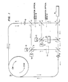
- Half-mirror 1, 2, 3 and 4 are disposed at the four corners of a square in a manner such that their surfaces are on the diagonal lines of the square.
- the optical path in the form of a square formed by connecting the centers of the half-mirrors 1, 2, 3 and 4 will be referred to as the separation optical path A.
- half-mirrors 5, 6, and 1 are disposed at the four corners of a square in a manner such that their surfaces are on the diagonal lines of this square.
- the optical path in the form of a square formed by connecting the centers of the half-mirrors 5, 6, 7 and 1 will be referred to as the separation optical path B.
- the separation optical paths A and -B both include the half-mirror 1.
- the half-mirrors 1, 2 and 5 are on one and the same straight line, as are the half-mirrors 1,4 and 7. These straight lines will be referred to as common separation lines 1-2-5 and 1-4-7, respectively.
- segments connecting the half-mirrors 3 and 4 and the half-mirrors 3 and 2 will be referred to as isolated separation paths 3-4 and 3-2, respectively.
- each of the separation optical paths A and B half of the path is made of a common separation path, and the remaining half is made up of an isolated separation path.
- a semiconductor laser 8 operates to oscillate a coherent light beam.
- the laser 8 is disposed on the extension of either the common separation path 1-2-5 or 1-4-7 behind the common half-mirror 1.
- Optical detectors 11 and 12 are disposed on the extension of the isolated separation paths 2-3 and 4-3, respectively.
- Optical detectors 13 and 14 are disposed on the extension of the isolated separation paths 5-6 and 6-7, respectively.
- An optical fiber loop 15 is obtained by winding a single mode optical fiber several turns.
- Lenses 9 and 10 are arranged on the extensions - of the common separation paths 1-2-5 and 1-4-7, so that the light beams are concentrated at the end face of the optical fibers, respectively.
- a rt/2 phase shifter 16 is inserted in one of the isolated separation paths of the separation optical path A.
- the phase shifter 16 is inserted in the isolated separation path 2-3.
- the optical detectors 11, 12, 13 and 14 provide outputs D1, D2, D3 and D4, respectively.
- the output D1 is given similarly as in the case of expression (7), thus including sin A6.
- the output D2 is not the same as expression (8).
- Light advances from a medium lower in refractive index towards a medium higher, where, when it is reflected, the electric field phase is shifted by ⁇ .
- the phase of the reflected light is shifted by ⁇
- the phase of the passed light is not shifted at all.
- Expression (3) with n added is added to expression (6) with n added, and the result of addition is squared to obtain the output D2.
- the sign of sin ⁇ is different.
- an expression approaching expression (10) can be provided.
- the outputs D3 and D4 of the optical detectors in the separation optical path B will now be described.
- the optical path B includes no phase shifter. Therefore, its output corresponds to expression (5).
- the output D3 is as follows:
- the output D4 is as follows: Thus, cos ⁇ can be obtained:
- Expressions (10) and (13) are applicable to the ideal case only. More specifically, these expressions can be established only under the conditions that the clockwise beam is equal in intensity to the counterclockwise beam, and each of the half-mirrors 1 through 7 transmits exactly 50% of the light and reflects 50%.
- the domain T is divided into n domains T 1 , ... T n .
- the absolute value of the differentiation dS 1 / d( ⁇ ) is made larger than the differentiations of other linear combinations of the sine and the cosine in the prime domain T 1 .
- ⁇ is determined from the value of the linear combination of the sine and the cosine S,.
- Linear combinations of the sine and the cosine S are all continuous single-valued linear combinations of the sine and the cosine in the domain T (- ⁇ /2 to ⁇ /2).
- sin ( ⁇ ) can be employed as the inclusion function.
- T is determined, ⁇ is accurately determined from the value of the corresponding linear combination of the sine and the cosine S,, because when ⁇ is included in T,, the linear combination of the sine and the cosine S 1 is higher in sensitivity than other linear combinations of the sine and the cosine.
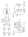
- Fig. 2 is a block diagram of a phase difference calculating circuit of the invention for the above-described case.
- reference characters D1 through D4 designate the outputs of the optical detectors.
- Subtractors 18 and 19 calculate sin ⁇ and cos ⁇ from D1 through D4, thus performing calculations as indicated by expressions (10) and (13).
- a subtractor 20 performs subtraction as indicated by expression (15), to obtain S 1 .
- An adder 21 performs addition as indicated by expression (17), to obtain S 3 .
- Fig. 3 indicates the linear combinations of the sine and the cosine S l , S 2 and S 3 plotted against the data ⁇ .
- a decision processing circuit 22 carries out the following process:
- the prime domains T 1 , T 2 and T 3 are as follows:
- the prime domain T 1 , T 2 and T 3 and the linear combinations of the sine and the cosine S1, 5 2 and S 3 may be as follows:
- the linear combination of the sine and the cosine S 1 can always determine ⁇ with the highest accuracy.
- n prime domain are equal in width.
- the separation optical paths A and B are provided to obtain sin ⁇ and cos ⁇ , which are subjected to linear coupling to obtain n linear combinations of the sine and the cosine.
- the data ⁇ - ⁇ should be close to rt/2.
- n linear combinations of the sine and the cosine can readily be determined from the two values (28) and (29).
- any phase difference ⁇ between the clockwise light beam (CW) and the counterclockwise light beam (CCW) in the optical fiber gyro can be determined with high accuracy.
Landscapes
- Physics & Mathematics (AREA)
- Engineering & Computer Science (AREA)
- Optics & Photonics (AREA)
- Electromagnetism (AREA)
- Power Engineering (AREA)
- General Physics & Mathematics (AREA)
- Radar, Positioning & Navigation (AREA)
- Remote Sensing (AREA)
- Gyroscopes (AREA)
Claims (8)


Applications Claiming Priority (2)
| Application Number | Priority Date | Filing Date | Title |
|---|---|---|---|
| JP57098995A JPS58215503A (ja) | 1982-06-09 | 1982-06-09 | 光フアイバジヤイロの処理方式 |
| JP98995/82 | 1982-06-09 |
Publications (3)
| Publication Number | Publication Date |
|---|---|
| EP0096416A2 EP0096416A2 (fr) | 1983-12-21 |
| EP0096416A3 EP0096416A3 (en) | 1986-03-19 |
| EP0096416B1 true EP0096416B1 (fr) | 1989-01-25 |
Family
ID=14234556
Family Applications (1)
| Application Number | Title | Priority Date | Filing Date |
|---|---|---|---|
| EP83105597A Expired EP0096416B1 (fr) | 1982-06-09 | 1983-06-07 | Gyroscope à fibre optique |
Country Status (5)
| Country | Link |
|---|---|
| US (1) | US4547072A (fr) |
| EP (1) | EP0096416B1 (fr) |
| JP (1) | JPS58215503A (fr) |
| CA (1) | CA1198198A (fr) |
| DE (1) | DE3379074D1 (fr) |
Families Citing this family (21)
| Publication number | Priority date | Publication date | Assignee | Title |
|---|---|---|---|---|
| JPS59206767A (ja) * | 1983-05-11 | 1984-11-22 | Japan Aviation Electronics Ind Ltd | 光干渉角速度計 |
| US4791460A (en) * | 1986-04-02 | 1988-12-13 | Honeywell Inc. | Readout for a ring laser angular rate sensor |
| CA2052074A1 (fr) * | 1990-10-29 | 1992-04-30 | Victor Vali | Capteur de gyroscope a optique integree |
| US5260768A (en) * | 1991-11-25 | 1993-11-09 | Litton Systems, Inc. | Fiber optic gyro with low-birefringence and PM networks |
| US7974505B2 (en) | 2007-10-17 | 2011-07-05 | Bae Systems Information And Electronic Systems Integration Inc. | Method for fabricating selectively coupled optical waveguides on a substrate |
| US8192638B2 (en) | 2007-10-18 | 2012-06-05 | Bae Systems Information And Electronic Systems Integration Inc. | Method for manufacturing multiple layers of waveguides |
| US7736934B2 (en) | 2007-10-19 | 2010-06-15 | Bae Systems Information And Electronic Systems Integration Inc. | Method for manufacturing vertical germanium detectors |
| WO2009055145A1 (fr) * | 2007-10-24 | 2009-04-30 | Bae Systems Information And Electronic Systems Integration Inc. | Procédé de fabrication d'un élément chauffant apte à ajuster l'indice de réfraction d'un guide d'ondes optiques |
| WO2009055778A1 (fr) | 2007-10-25 | 2009-04-30 | Bae Systems Information And Electronic Systems Integration Inc. | Procédé pour fabriquer des détecteurs latéraux au germanium |
| US7811844B2 (en) | 2007-10-26 | 2010-10-12 | Bae Systems Information And Electronic Systems Integration Inc. | Method for fabricating electronic and photonic devices on a semiconductor substrate |
| WO2009058469A2 (fr) * | 2007-10-29 | 2009-05-07 | Bae Systems Information And Electronic Systems Integration Inc. | Gyroscope optique à guide d'onde à contraste d'indice élevé ayant des chemins segmentés |
| WO2009058470A1 (fr) * | 2007-10-30 | 2009-05-07 | Bae Systems Information And Electronic Systems Integration Inc. | Procédé de fabrication de modulateurs électro-absorbants couplés bout à bout |
| US20100140587A1 (en) * | 2007-10-31 | 2010-06-10 | Carothers Daniel N | High-Injection Heterojunction Bipolar Transistor |
| US7987066B2 (en) * | 2008-08-29 | 2011-07-26 | Bae Systems Information And Electronic Systems Integration Inc. | Components and configurations for test and valuation of integrated optical busses |
| US7715663B2 (en) * | 2008-08-29 | 2010-05-11 | Bae Systems Information And Electronic Systems Integration Inc. | Integrated optical latch |
| US8148265B2 (en) * | 2008-08-29 | 2012-04-03 | Bae Systems Information And Electronic Systems Integration Inc. | Two-step hardmask fabrication methodology for silicon waveguides |
| US8288290B2 (en) * | 2008-08-29 | 2012-10-16 | Bae Systems Information And Electronic Systems Integration Inc. | Integration CMOS compatible of micro/nano optical gain materials |
| US7853101B2 (en) * | 2008-08-29 | 2010-12-14 | Bae Systems Information And Electronic Systems Integration Inc. | Bi-rate adaptive optical transfer engine |
| US7693354B2 (en) * | 2008-08-29 | 2010-04-06 | Bae Systems Information And Electronic Systems Integration Inc. | Salicide structures for heat-influenced semiconductor applications |
| US7847353B2 (en) * | 2008-12-05 | 2010-12-07 | Bae Systems Information And Electronic Systems Integration Inc. | Multi-thickness semiconductor with fully depleted devices and photonic integration |
| US9305779B2 (en) * | 2009-08-11 | 2016-04-05 | Bae Systems Information And Electronic Systems Integration Inc. | Method for growing germanium epitaxial films |
Family Cites Families (2)
| Publication number | Priority date | Publication date | Assignee | Title |
|---|---|---|---|---|
| US4280766A (en) * | 1977-11-21 | 1981-07-28 | The United States Of America As Represented By The Administrator Of The National Aeronautics And Space Administration | Optical gyroscope system |
| FR2475220A1 (fr) * | 1980-02-01 | 1981-08-07 | Electricite De France | Dispositif de detection d'ondes electromagnetiques, typiquement lumineuses, en quadrature de phase avec balance heterodyne. application aux velocimetres doppler et gyrometres sagnac |
-
1982
- 1982-06-09 JP JP57098995A patent/JPS58215503A/ja active Granted
-
1983
- 1983-06-07 DE DE8383105597T patent/DE3379074D1/de not_active Expired
- 1983-06-07 US US06/502,063 patent/US4547072A/en not_active Expired - Lifetime
- 1983-06-07 EP EP83105597A patent/EP0096416B1/fr not_active Expired
- 1983-06-08 CA CA000429961A patent/CA1198198A/fr not_active Expired
Also Published As
| Publication number | Publication date |
|---|---|
| EP0096416A3 (en) | 1986-03-19 |
| CA1198198A (fr) | 1985-12-17 |
| JPS6323485B2 (fr) | 1988-05-17 |
| EP0096416A2 (fr) | 1983-12-21 |
| US4547072A (en) | 1985-10-15 |
| JPS58215503A (ja) | 1983-12-15 |
| DE3379074D1 (en) | 1989-03-02 |
Similar Documents
| Publication | Publication Date | Title |
|---|---|---|
| US4547072A (en) | Optical fiber gyro | |
| US4440498A (en) | Optical fiber gyroscope with (3×3) directional coupler | |
| US5465149A (en) | Lightwave phase control for reduction of resonator fiber optic gyroscope Kerr effect error | |
| US5074665A (en) | Fiber optic gyroscope using dual-section counter-wound coil | |
| EP3514491B1 (fr) | Appareil et procédé pour diminuer l'erreur de biais due à une discordance de polarisation | |
| US9644966B2 (en) | Integrated optic circuit with waveguides stitched at supplementary angles for reducing coherent backscatter | |
| US5349441A (en) | Fiber optic gyroscope refractive index induced error compensation | |
| US5602642A (en) | Magnetically insensitive fiber optic rotation sensor | |
| JPH07190787A (ja) | 回転速度を測定するための光ファイバサニャック干渉計 | |
| EP0078931B1 (fr) | Sensor de vitesse angulaire | |
| US4566794A (en) | Apparatus for interference fringe shift sensing | |
| US20030169428A1 (en) | Saw tooth bias modulation and loop closure for an interferometric fiber optic gyroscope | |
| GB2067746A (en) | Measurement of rotation rate using sagnac effect | |
| US5214487A (en) | Fiber optic gyro | |
| US4290697A (en) | Method to eliminate fiber interferometer reflections | |
| EP0059644A1 (fr) | Gyroscope optique | |
| EP4567380B1 (fr) | Circuit optique pour compenser des fluctuations de conducteurs optiques dans un rfog | |
| JPH0558486B2 (fr) | ||
| JPS61169714A (ja) | 光フアイバジヤイロ | |
| JPS60135816A (ja) | 光フアイバジヤイロ | |
| Ohtsuka | Optical heterodyne-detection schemes for fiber-optic gyroscopes | |
| JPH02189412A (ja) | 光フアイバジヤイロ | |
| EP0509511A2 (fr) | Gyroscope à fibre optique du type à modulation de phase | |
| JPH02266216A (ja) | 光ファイバジャイロ | |
| JPS6212812A (ja) | 光干渉角速度計 |
Legal Events
| Date | Code | Title | Description |
|---|---|---|---|
| PUAI | Public reference made under article 153(3) epc to a published international application that has entered the european phase |
Free format text: ORIGINAL CODE: 0009012 |
|
| AK | Designated contracting states |
Designated state(s): DE FR GB NL SE |
|
| PUAL | Search report despatched |
Free format text: ORIGINAL CODE: 0009013 |
|
| AK | Designated contracting states |
Kind code of ref document: A3 Designated state(s): DE FR GB NL SE |
|
| 17P | Request for examination filed |
Effective date: 19860515 |
|
| 17Q | First examination report despatched |
Effective date: 19871026 |
|
| GRAA | (expected) grant |
Free format text: ORIGINAL CODE: 0009210 |
|
| AK | Designated contracting states |
Kind code of ref document: B1 Designated state(s): DE FR GB NL SE |
|
| REF | Corresponds to: |
Ref document number: 3379074 Country of ref document: DE Date of ref document: 19890302 |
|
| ET | Fr: translation filed | ||
| PLBE | No opposition filed within time limit |
Free format text: ORIGINAL CODE: 0009261 |
|
| STAA | Information on the status of an ep patent application or granted ep patent |
Free format text: STATUS: NO OPPOSITION FILED WITHIN TIME LIMIT |
|
| 26N | No opposition filed | ||
| EAL | Se: european patent in force in sweden |
Ref document number: 83105597.5 |
|
| PGFP | Annual fee paid to national office [announced via postgrant information from national office to epo] |
Ref country code: DE Payment date: 20000605 Year of fee payment: 18 |
|
| PGFP | Annual fee paid to national office [announced via postgrant information from national office to epo] |
Ref country code: SE Payment date: 20000606 Year of fee payment: 18 |
|
| PGFP | Annual fee paid to national office [announced via postgrant information from national office to epo] |
Ref country code: GB Payment date: 20000607 Year of fee payment: 18 |
|
| PGFP | Annual fee paid to national office [announced via postgrant information from national office to epo] |
Ref country code: FR Payment date: 20000612 Year of fee payment: 18 |
|
| PGFP | Annual fee paid to national office [announced via postgrant information from national office to epo] |
Ref country code: NL Payment date: 20000629 Year of fee payment: 18 |
|
| PG25 | Lapsed in a contracting state [announced via postgrant information from national office to epo] |
Ref country code: GB Free format text: LAPSE BECAUSE OF NON-PAYMENT OF DUE FEES Effective date: 20010607 |
|
| PG25 | Lapsed in a contracting state [announced via postgrant information from national office to epo] |
Ref country code: SE Free format text: LAPSE BECAUSE OF NON-PAYMENT OF DUE FEES Effective date: 20010608 |
|
| PG25 | Lapsed in a contracting state [announced via postgrant information from national office to epo] |
Ref country code: NL Free format text: LAPSE BECAUSE OF NON-PAYMENT OF DUE FEES Effective date: 20020101 |
|
| GBPC | Gb: european patent ceased through non-payment of renewal fee |
Effective date: 20010607 |
|
| EUG | Se: european patent has lapsed |
Ref document number: 83105597.5 |
|
| PG25 | Lapsed in a contracting state [announced via postgrant information from national office to epo] |
Ref country code: FR Free format text: LAPSE BECAUSE OF NON-PAYMENT OF DUE FEES Effective date: 20020228 |
|
| NLV4 | Nl: lapsed or anulled due to non-payment of the annual fee |
Effective date: 20020101 |
|
| PG25 | Lapsed in a contracting state [announced via postgrant information from national office to epo] |
Ref country code: DE Free format text: LAPSE BECAUSE OF NON-PAYMENT OF DUE FEES Effective date: 20020403 |