EP0096488A1 - Drehschwingungsdämpfer mit regelbarer Federsenkung und Reibungsdämpfung - Google Patents
Drehschwingungsdämpfer mit regelbarer Federsenkung und Reibungsdämpfung Download PDFInfo
- Publication number
- EP0096488A1 EP0096488A1 EP83302825A EP83302825A EP0096488A1 EP 0096488 A1 EP0096488 A1 EP 0096488A1 EP 83302825 A EP83302825 A EP 83302825A EP 83302825 A EP83302825 A EP 83302825A EP 0096488 A1 EP0096488 A1 EP 0096488A1
- Authority
- EP
- European Patent Office
- Prior art keywords
- plate
- friction
- hub
- clutch driven
- windows
- Prior art date
- Legal status (The legal status is an assumption and is not a legal conclusion. Google has not performed a legal analysis and makes no representation as to the accuracy of the status listed.)
- Withdrawn
Links
Images



Classifications
-
- F—MECHANICAL ENGINEERING; LIGHTING; HEATING; WEAPONS; BLASTING
- F16—ENGINEERING ELEMENTS AND UNITS; GENERAL MEASURES FOR PRODUCING AND MAINTAINING EFFECTIVE FUNCTIONING OF MACHINES OR INSTALLATIONS; THERMAL INSULATION IN GENERAL
- F16F—SPRINGS; SHOCK-ABSORBERS; MEANS FOR DAMPING VIBRATION
- F16F15/00—Suppression of vibrations in systems; Means or arrangements for avoiding or reducing out-of-balance forces, e.g. due to motion
- F16F15/10—Suppression of vibrations in rotating systems by making use of members moving with the system
- F16F15/12—Suppression of vibrations in rotating systems by making use of members moving with the system using elastic members or friction-damping members, e.g. between a rotating shaft and a gyratory mass mounted thereon
- F16F15/129—Suppression of vibrations in rotating systems by making use of members moving with the system using elastic members or friction-damping members, e.g. between a rotating shaft and a gyratory mass mounted thereon characterised by friction-damping means
Definitions
- Clutch driven plates generally utilize vibration damping means in a manually-actuated vehicle transmission to overcome objectionable vibration and rattle during the torsional coupling of the engine driven shaft and the transmission input shaft by a friction clutch.
- a conventional vibration damper assembly includes a hub having an internally splined passage to receive the splined end of a transmission input shaft and a radial flange, a clutch plate journalled on the hub and carrying the friction facings at its periphery, a spring retainer plate journalled on the hub on the opposite side of the hub flange from the clutch plate, and damper springs positioned in axially aligned sets of spring windows in the hub flange and the clutch and spring retainer plates.
- the clutch plate and spring retainer plate are connected together by stop pins extending through elongated peripheral notches in the hub flange.
- This damper assembly provides for a substantially constant rate of energy dissipation, and friction washers may be positioned between the hub flange and the clutch and spring retainer plates to provide additional damping friction in predetermined stages.
- the above described vibration damper assembly has proved to be inadequate where specialized problems occur, such as gear rattle at an idle condition, necessitating a multi-stage vibration damping arrangement, with or without friction damping in the stages.
- the present invention provides such a multi-stage damper to overcome the specialized problems encountered in a vehicle drive line.
- the present invention comprehends the provision of a multi-stage vibration damper in a friction clutch plate to provide a low spring rate first stage with zero or low damping friction for the initial travel and a second stage of travel with an increased spring rate and increased damping friction as required for the remaining travel of the damper assembly.
- the first stage of travel utilizes a pair of diametrically opposed low rate compression springs with substantially no friction damping
- the second stage of travel utilizes four sets of compression damping springs having a higher spring rate; the second stage being accompanied by movement of a friction plate together with a spring retainer plate of the clutch plate assembly.
- the friction plate includes peripheral tangs received in notches formed in the inner periphery of the retainer plate, the slots being dimensioned to provide relative lost motion during the first stage of travel of the damper assembly.
- the present invention also comprehends the provision of a multi-stage vibration damper assembly which will provide damping friction variations of zero friction, single friction or double friction as desired by addition of a second friction plate and by modification of the clearances between the slot and tang connection of the friction plates in the vibration damper assembly.
- a first friction plate is positioned within the inner periphery of and in the same plane of the spring retainer plate while the second friction plate is located between parallel thrust plates adjacent the spring retainer plate and has forwardly projecting tangs received in slots formed in the retainer plate at a larger diameter than the diameter of the first friction plate.
- the second friction plate will be picked up at the same or a later point than the first friction plate upon the rotary movement of the spring retainer plate.
- Figures 1 through 4 disclose a clutch driven plate assembly 10 having a two-stage vibration damper within the assembly to provide multi-stage vibration damping.
- the clutch plate assembly includes a hub with a generally tubular barrel 11 and having flattened portions 20 and an integral radial flange 12 intermediate the ends of the barrel and formed with a pair of diametrically opposed smaller spring windows 13 and four circumferentially spaced larger spring windows 14.
- the periphery 15 of the flange is provided with elongated arcuate notches 16 to receive stop pins 17.
- a clutch driven plate 18 is journalled at its inner periphery 19 on the hub barrel 11 and carries annular friction facings 21 adjacent its outer periphery; the facings being secured to the plate by rivets 22.
- the plate has a pair of smaller spring windows 23, four larger spring windows 24 and a plurality of openings 25 to receive an end of each stop pin 17.
- a spring retainer plate 26 located on the opposite side of the hub flange 12 has a pair of smaller spring windows 27, four larger spring windows 28 and a plurality of openings 29 to receive the opposite ends of the stop pins 17.
- the inner periphery 31 of the plate 26 is spaced outwardly from the hub barrel 11 and is provided with a plurality of circumferentially spaced notches 32 for a purpose to be later described.
- Each set of smaller spring windows 13,23 and 27 are all of the same arcuate length and are axially aligned to receive a low rate compression spring 33 therein for the first stage of travel.
- each set of larger spring windows 14,24 and 28 are axially aligned to receive damper springs or spring sets 34; the windows 14 in the hub flange 12 being a greater arcuate length than the windows 24 and 28 to provide limited lost motion in operation of the damper.
- Journalled on the hub barrel 11 is a generally annular friction plate 35 having circumferentially spaced tangs 36 on the outer periphery received in the notches 32 of the spring retainer plate 26; both the plate 26 and friction plate 35 lying in a common plane and in sliding engagement with the side of the hub flange 12.
- An annular thrust plate 37 having inner flattened surfaces 38 cooperating with the hub flats on the barrel 11 remains stationary with the hub barrel in frictional sliding engagement with the rotating friction plate 35, and a Belleville spring 39 is located on the barrel against the thrust plate 37 and retained by a snap ring 40 received in a groove 41 in the barrel.
- the Belleville spring 39 urges the thrust plate 37 against the friction plate 35 to create frictional sliding engagement with the hub flange 12.
- Each notch 32 has a greater arcuate length than the tang 36 received therein to provide a clearance "x" ( Figure 3) in one or both of the drive and coast directions.
- the tangs are desirably picked up when the higher rate springs 34 contact the hub flange to be compressed for the second stage of travel.
- the assembly then provides the requisite damping action between the friction facings and the hub barrel transmitting torque to the transmission input shaft received in the splined passage 42 in the hub barrel.
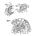
- FIGs 5 through 10 disclose an alternate embodiment of damper assembly 45 wherein the parts identical to those of Figures 1 through 4 will have the same reference numeral with a script a.
- This assembly includes a clutch hub having a barrel 11a having flats 20a and flange 12a, a clutch driven plate 18a journallec on the hub barrel and carrying the friction facings 21a, and a spring retainer plate 26a secured tc the clutch plate 18a by stop pins 17a extending through peripheral notches 16a in the hub flange 12a.
- Small spring windows 13a, 23a and 27a in the hub flange 12a, clutch plate 18a and spring retainer plate 26a, respectively, have equal lengths and are axially aligned tc receive low rate damper springs 33a.
- the larger spring windows 14a, 24a and 28a are axially aligned to receive higher rate damper springs 34a; the windows 14a having a greater length than the windows 24a and 28a to provide lost motion between the springs 34a and flange 12a during the first stage of travel.
- the inner periphery 31 a of the spring retainer plate 26a is provided with notches 32a to receive the tangs 36a of the friction plate 35a; the notches providing a distance "x" ( Figure 8) on each side of the tangs 36a.
- a first thrust plate 37a having flats 38a is biased by the Belleville spring 39a frictionally against the friction plate 35a, while a second thrust plate 46 having flats 47 parallels the first thrust plate 37a and is directly engaged by the Belleville spring 39a.
- Located between the thrust plates 37a and 46 is a second friction plate 48 journalled on the hub barrel 11a.
- the outer periphery 49 of plate 48 is provided with outwardly and then forwardly extending ears or tangs 50 which are received in elongated arcuate slots 51 in the spring retainer plate 26a; the slots 51 being positioned between and radially outwardly of the notches 32a in the inner periphery 31a.
- the slots 51 provide a circumferential clearance "y" ( Figure 8) relative to the tangs 50.
- This alternate embodiment 45 provides damping friction variations of zero or low friction, single friction our double friction as desired by modifying the clearance "x" and "y” as seen in Figure 8, between the tangs and slots or notches in the damping friction area.
- One arrangement utilizes an equal clearance in both the notches 32a and the slots 51 to provide double friction in the second stage of travel.
- initial application of torque to the clutch plate 18a causes rotation of the plates 18a and 26a relative to the hub flange 12a compressing the low rate springs 33a until the springs 34a contact the edges of spring windows 14a of the hub flange; the plate 26a also moving relative to the friction plates 35a and 48.
- the notches 32a and slots 51 pick up the tangs 36a and 50, respectively to provide double friction resulting from the Belleville spring 39a and thrust plates 37a and 46 acting on the friction plates 35a and 48.
- Figure 10 discloses the travel of the damper assembly as all of the springs 33a and 34a are compressed until the stop pins 17a move to and contact the ends of the elongated notches 16a.
- the relative angular position of the retainer plate 26a to the friction plates 35a and 48 remains the same as in Figure 9 and only the angular relationship to the hub 11a has changed due to the continued travel.
Landscapes
- Engineering & Computer Science (AREA)
- General Engineering & Computer Science (AREA)
- Physics & Mathematics (AREA)
- Acoustics & Sound (AREA)
- Aviation & Aerospace Engineering (AREA)
- Mechanical Engineering (AREA)
- Mechanical Operated Clutches (AREA)
Applications Claiming Priority (2)
| Application Number | Priority Date | Filing Date | Title |
|---|---|---|---|
| US386567 | 1982-06-09 | ||
| US06/386,567 US4485908A (en) | 1982-06-09 | 1982-06-09 | Vibration damper with variable rate springs and damping friction |
Publications (1)
| Publication Number | Publication Date |
|---|---|
| EP0096488A1 true EP0096488A1 (de) | 1983-12-21 |
Family
ID=23526136
Family Applications (1)
| Application Number | Title | Priority Date | Filing Date |
|---|---|---|---|
| EP83302825A Withdrawn EP0096488A1 (de) | 1982-06-09 | 1983-05-18 | Drehschwingungsdämpfer mit regelbarer Federsenkung und Reibungsdämpfung |
Country Status (7)
| Country | Link |
|---|---|
| US (1) | US4485908A (de) |
| EP (1) | EP0096488A1 (de) |
| JP (1) | JPS5943225A (de) |
| AR (1) | AR230865A1 (de) |
| AU (1) | AU1504883A (de) |
| BR (1) | BR8303055A (de) |
| ES (1) | ES8405116A1 (de) |
Cited By (2)
| Publication number | Priority date | Publication date | Assignee | Title |
|---|---|---|---|---|
| GB2163831A (en) * | 1984-08-30 | 1986-03-05 | Fichtel & Sachs Ag | Torsional vibration damper |
| EP0459557A3 (en) * | 1990-06-01 | 1992-08-12 | General Motors Corporation | Clutch and damper assembly |
Families Citing this family (17)
| Publication number | Priority date | Publication date | Assignee | Title |
|---|---|---|---|---|
| US4643287A (en) * | 1982-09-27 | 1987-02-17 | Borg-Warner Corporation | Multi-stage torsional damping device |
| DE3242933A1 (de) * | 1982-11-20 | 1984-05-24 | LuK Lamellen und Kupplungsbau GmbH, 7580 Bühl | Kupplungsscheibe |
| US4586596A (en) * | 1983-03-23 | 1986-05-06 | Luk Lamellen Und Kupplungsbau Gmbh | Clutch plate with a composite torsion damping hub |
| US4553655A (en) * | 1983-11-30 | 1985-11-19 | Borg-Warner Corporation | Two-stage clutch damper assembly |
| FR2568642B1 (fr) * | 1984-08-03 | 1990-06-15 | Valeo | Dispositif amortisseur de torsion a grand debattement angulaire, en particulier friction d'embrayage, notamment pour vehicule automobile |
| USRE34648E (en) * | 1984-09-11 | 1994-06-28 | Valeo | Clutch plate having two stage torsion damping means |
| DE3448538C2 (de) * | 1984-11-23 | 1996-08-29 | Luk Lamellen & Kupplungsbau | Torsionsschwingungsdämpfer |
| GB8708536D0 (en) * | 1987-04-09 | 1987-05-13 | Automotive Prod Plc | Torsional vibration damper |
| US4991704A (en) * | 1989-11-28 | 1991-02-12 | Dana Corporation | Apparatus for adjusting hysteresis in a clutch |
| US5007517A (en) * | 1989-12-27 | 1991-04-16 | Dana Corporation | Adjustable hysteresis damper |
| USRE33984E (en) * | 1990-06-01 | 1992-07-07 | General Motors Corporation | Clutch damper assembly |
| JP2001343061A (ja) * | 2000-03-27 | 2001-12-14 | Nsk Warner Kk | 多板ロックアップクラッチ及び該多板ロックアップクラッチを内蔵したトルクコンバータ装置 |
| JP4298992B2 (ja) * | 2002-06-07 | 2009-07-22 | 株式会社エクセディ | ダンパーディスク組立体 |
| US20060223640A1 (en) * | 2005-04-05 | 2006-10-05 | Bassett Michael L | Rotational coupling with overload protection |
| CN113124099B (zh) * | 2020-01-15 | 2025-11-14 | 舍弗勒技术股份两合公司 | 车辆用减振器及车辆 |
| CN112128263B (zh) * | 2020-10-28 | 2024-03-29 | 广西玉柴机器股份有限公司 | 一种低震动的离合器从动盘 |
| CN114909434B (zh) * | 2022-05-11 | 2022-11-25 | 湖北三环离合器有限公司 | 一种限扭减振器 |
Citations (4)
| Publication number | Priority date | Publication date | Assignee | Title |
|---|---|---|---|---|
| FR1349574A (fr) * | 1962-02-09 | 1964-01-17 | Borg Warner | Amortisseur de vibrations, notamment pour embrayage |
| FR1501465A (fr) * | 1965-11-20 | 1965-11-10 | Fichtel & Sachs Ag | Disque d'embrayage à amortisseurs d'oscillations |
| FR2000871A1 (de) * | 1968-01-27 | 1969-09-12 | Fichtel & Sachs Ag | |
| GB2083592A (en) * | 1980-09-10 | 1982-03-24 | Automotive Prod Co Ltd | A friction clutch driven plate |
Family Cites Families (11)
| Publication number | Priority date | Publication date | Assignee | Title |
|---|---|---|---|---|
| US1952892A (en) * | 1929-04-24 | 1934-03-27 | Borg & Beck Co | Clutch plate |
| US1966948A (en) * | 1933-05-17 | 1934-07-17 | George F Forsythe | Vibration dampening motion transmitting element |
| US2097627A (en) * | 1933-07-26 | 1937-11-02 | Spicer Mfg Corp | Vibration dampener |
| US2118913A (en) * | 1934-11-24 | 1938-05-31 | Autocar Company | Power transmitting mechanism |
| US2745268A (en) * | 1952-07-01 | 1956-05-15 | Borg Warner | Clutch driven plate |
| US3408830A (en) * | 1966-08-25 | 1968-11-05 | Eaton Yale & Towne | Torsion drive assembly |
| DE2318908C3 (de) * | 1973-04-14 | 1980-04-24 | Daimler-Benz Ag, 7000 Stuttgart | Kupplungsscheibe fur Kraftfahrzeug-Hauptkupplungen |
| DE2318907C2 (de) * | 1973-04-14 | 1975-05-28 | Daimler-Benz Ag, 7000 Stuttgart | Kupplungsscheibe für Kraftfahrzeug-Hauptkupplungen |
| DE2338394C2 (de) * | 1973-07-28 | 1975-05-22 | Daimler-Benz Ag, 7000 Stuttgart | Kupplungsscheibe für Kraftfahrzeug- Hauptkupplungen |
| GB1564974A (en) * | 1977-01-04 | 1980-04-16 | Automotive Prod Co Ltd | Friction clutches |
| US4446955A (en) * | 1980-07-03 | 1984-05-08 | Borg-Warner Corporation | Clutch driven plate assembly with a floating hub |
-
1982
- 1982-06-09 US US06/386,567 patent/US4485908A/en not_active Expired - Fee Related
-
1983
- 1983-05-18 EP EP83302825A patent/EP0096488A1/de not_active Withdrawn
- 1983-05-27 AU AU15048/83A patent/AU1504883A/en not_active Abandoned
- 1983-06-03 AR AR293233A patent/AR230865A1/es active
- 1983-06-08 BR BR8303055A patent/BR8303055A/pt unknown
- 1983-06-08 ES ES523086A patent/ES8405116A1/es not_active Expired
- 1983-06-08 JP JP58101032A patent/JPS5943225A/ja active Pending
Patent Citations (4)
| Publication number | Priority date | Publication date | Assignee | Title |
|---|---|---|---|---|
| FR1349574A (fr) * | 1962-02-09 | 1964-01-17 | Borg Warner | Amortisseur de vibrations, notamment pour embrayage |
| FR1501465A (fr) * | 1965-11-20 | 1965-11-10 | Fichtel & Sachs Ag | Disque d'embrayage à amortisseurs d'oscillations |
| FR2000871A1 (de) * | 1968-01-27 | 1969-09-12 | Fichtel & Sachs Ag | |
| GB2083592A (en) * | 1980-09-10 | 1982-03-24 | Automotive Prod Co Ltd | A friction clutch driven plate |
Cited By (3)
| Publication number | Priority date | Publication date | Assignee | Title |
|---|---|---|---|---|
| GB2163831A (en) * | 1984-08-30 | 1986-03-05 | Fichtel & Sachs Ag | Torsional vibration damper |
| US4687087A (en) * | 1984-08-30 | 1987-08-18 | Fichtel & Sachs Ag | Torsional vibration damper |
| EP0459557A3 (en) * | 1990-06-01 | 1992-08-12 | General Motors Corporation | Clutch and damper assembly |
Also Published As
| Publication number | Publication date |
|---|---|
| AR230865A1 (es) | 1984-07-31 |
| AU1504883A (en) | 1983-12-15 |
| ES523086A0 (es) | 1984-05-16 |
| US4485908A (en) | 1984-12-04 |
| ES8405116A1 (es) | 1984-05-16 |
| JPS5943225A (ja) | 1984-03-10 |
| BR8303055A (pt) | 1984-01-31 |
Similar Documents
| Publication | Publication Date | Title |
|---|---|---|
| US4485908A (en) | Vibration damper with variable rate springs and damping friction | |
| US4347717A (en) | Two-stage torsional vibration damper | |
| EP0136825B1 (de) | Änderungen an einer Serie von Schwingungsdämpfern mit Feder | |
| US4279132A (en) | Vibration damper assembly | |
| US4795012A (en) | Spiral spring disc torsional coupling | |
| US4485909A (en) | Multiple stage vibration damper | |
| EP0061827B1 (de) | Langhubiger Dämpfer für die Überbrückungskupplung eines Strömungswandlers | |
| US4304107A (en) | Series spring torsional vibration damper | |
| US4562913A (en) | Friction clutch driven plate | |
| US4113075A (en) | Centrifugal lock-up clutch and torque converter | |
| CA1264450A (en) | Long travel series damper for continuously variable transmission | |
| US4471863A (en) | Multi-stage torsional damping device | |
| US5004088A (en) | Torsional vibration damper | |
| US4302951A (en) | Torsional vibration damper | |
| EP0216476A1 (de) | Aufbau einer Kupplungsscheibe mit proportionaler Verzögerung der Reibung | |
| US4679679A (en) | Clutch driven plate assembly with anti-backlash damping | |
| US5020647A (en) | Lock-up damper device for torque converter | |
| US4303149A (en) | Clutch driven plate with spline locking hub | |
| US4875562A (en) | Lock-up damper for torque converter | |
| US4556136A (en) | Clutch driven plate assembly | |
| US5401213A (en) | Clutch and damper assembly | |
| US4285423A (en) | Clutch disc assembly | |
| US4651859A (en) | Clutch driven plate assembly with a two-part hub | |
| US5139122A (en) | Torque converter including a lock-up clutch | |
| JPH09196078A (ja) | ダンパーディスク組立体 |
Legal Events
| Date | Code | Title | Description |
|---|---|---|---|
| PUAI | Public reference made under article 153(3) epc to a published international application that has entered the european phase |
Free format text: ORIGINAL CODE: 0009012 |
|
| AK | Designated contracting states |
Designated state(s): DE FR GB IT SE |
|
| 17P | Request for examination filed |
Effective date: 19831215 |
|
| STAA | Information on the status of an ep patent application or granted ep patent |
Free format text: STATUS: THE APPLICATION IS DEEMED TO BE WITHDRAWN |
|
| 18D | Application deemed to be withdrawn |
Effective date: 19860620 |
|
| RIN1 | Information on inventor provided before grant (corrected) |
Inventor name: GATEWOOD, SIDNEY ULANE |