EP0096588A2 - Bausatz zum Abdichten von Türen - Google Patents
Bausatz zum Abdichten von Türen Download PDFInfo
- Publication number
- EP0096588A2 EP0096588A2 EP83303296A EP83303296A EP0096588A2 EP 0096588 A2 EP0096588 A2 EP 0096588A2 EP 83303296 A EP83303296 A EP 83303296A EP 83303296 A EP83303296 A EP 83303296A EP 0096588 A2 EP0096588 A2 EP 0096588A2
- Authority
- EP
- European Patent Office
- Prior art keywords
- door
- sealing member
- edge
- sealing
- aperture
- Prior art date
- Legal status (The legal status is an assumption and is not a legal conclusion. Google has not performed a legal analysis and makes no representation as to the accuracy of the status listed.)
- Granted
Links
- 238000007789 sealing Methods 0.000 title claims abstract description 56
- 238000010008 shearing Methods 0.000 claims abstract description 7
- 235000014443 Pyrus communis Nutrition 0.000 claims description 3
- 229920000915 polyvinyl chloride Polymers 0.000 claims 2
- 239000004800 polyvinyl chloride Substances 0.000 claims 2
- 239000000463 material Substances 0.000 description 4
- 238000010276 construction Methods 0.000 description 3
- 238000005096 rolling process Methods 0.000 description 3
- 230000006835 compression Effects 0.000 description 2
- 238000007906 compression Methods 0.000 description 2
- 239000012212 insulator Substances 0.000 description 2
- 238000010079 rubber tapping Methods 0.000 description 2
- 230000015556 catabolic process Effects 0.000 description 1
- 239000004020 conductor Substances 0.000 description 1
- 238000006731 degradation reaction Methods 0.000 description 1
- 239000002184 metal Substances 0.000 description 1
Images


Classifications
-
- E—FIXED CONSTRUCTIONS
- E06—DOORS, WINDOWS, SHUTTERS, OR ROLLER BLINDS IN GENERAL; LADDERS
- E06B—FIXED OR MOVABLE CLOSURES FOR OPENINGS IN BUILDINGS, VEHICLES, FENCES OR LIKE ENCLOSURES IN GENERAL, e.g. DOORS, WINDOWS, BLINDS, GATES
- E06B7/00—Special arrangements or measures in connection with doors or windows
- E06B7/16—Sealing arrangements on wings or parts co-operating with the wings
- E06B7/22—Sealing arrangements on wings or parts co-operating with the wings by means of elastic edgings, e.g. elastic rubber tubes; by means of resilient edgings, e.g. felt or plush strips, resilient metal strips
- E06B7/23—Plastic, sponge rubber, or like strips or tubes
- E06B7/2305—Plastic, sponge rubber, or like strips or tubes with an integrally formed part for fixing the edging
- E06B7/2307—Plastic, sponge rubber, or like strips or tubes with an integrally formed part for fixing the edging with a single sealing-line or -plane between the wing and the part co-operating with the wing
- E06B7/2309—Plastic, sponge rubber, or like strips or tubes with an integrally formed part for fixing the edging with a single sealing-line or -plane between the wing and the part co-operating with the wing with a hollow sealing part
Definitions
- This invention relates to an assembly for sealing doors more particularly, but not exclusively to sealing refrigerated van doors.
- a flexible seal of substantially 'U' shaped cross section is provided, the arms of the 'U' extend in a direction parallel to the plane of the door and co-operate with a door frame or pillar surrounding the door to be sealed.
- the lengths of the arms are crucial because too short a length would not ensure a sufficient seal and too long a length would increase the resistance necessary to pull open the sealed door due to the tips of the arms becoming bent and catching the door frame or pillar.
- Such seals are susceptible to wear and tear and therefore need replacing, this involves complete dismantling of the sealing arrangement. In addition to being unnecessarily expensive to replace it is also time consuming during which time the van is rendered inoperative and meanwhile losing I>business.
- Hollow seals have previously been proposed having a circular cross-section but these have previously only been used as a compression seal and therefor extend in a direction transverse to the plane to the door.
- the door 1 has parallel front and back panels 10 and 11 respectively.
- the front panel 10 extends slightly beyond the back panel 11.
- the sealing assembly is attached on each edge of the door between the front and back panels 10 and 11 and comprises a substantially rigid member 2 for attachment to the inside of the panels 10 and 11 in the region of the periphery thereof for closing the gap therebetween.
- the rigid member 2 is preferably arranged to lie substantially flush with the periphery of the panels 10 and 11 and because the front panel 10 extends slightly beyond the back panel 11 the rigid member 2 tapers along a substantial length between one panel and the other.
- the rigid member 2 has a recess 3 between the front and back panels for receiving a holder 4 which has a C-shaped cross section and may have serrated sides for additional grip with the recess 3 when the rigid member 2 is moulded around the holder 4.
- a first sealing member 5 made from suitably flexible material such as P.V.C. capable of being compressed and advantageously capable of withstanding temperatures in the region of -40°c without degradation of its properties and having retaining means 14 extending from the base thereof for being removably located in said holder.
- the sealing member 5 protrudes outwardly from the holder 4 in a direction parallel to the plane of the door and in use communicates in a compressed condition with a door frame or pillar 9 surrounding the door 1. Between the frame 9 and the door 1 there is provided a gap no less than the height of the seal when fully compressed so as to enable the seal to be inserted.
- FIG. 1 One type of door frame to be sealed with the door including a sealing assembly as described above is shown in Figure 1 in which the door frame 9 may be provided with a tapping plate 13 preferably welded on the inside of the outer wall of the door frame similarly a tapping plate 13 may be provided on the inside of the front panel 10 of the door 1, for providing means to hinge the door 1 on either side of the frame 9.
- the door frame 9 may be surrounded by a shield 12 as shown in Figures 1 and 2 but advantageously the part of the door frame 9 which co-operates with the seal 5 when in use should be heat insulative.
- the shield 12 may be isolated from the intei-ioroof the container by providing a suitable heat break with which the sealing member 5 co-operates when the door is in position in the door frame 9 as shown in Figure 2.
- shield 12 and the plate or wall 7 may be made of the same material and may be of one material moulded or bent around the heat break 6.
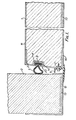
- FIG. 3 Another variation of the door frame construction is shown in Figure 3 in which the door frame 9 has an edge which is of registering shape to the edge of the door 1 i.e. the door frame has a first portion extending substantially at right angles from the outer wall 12 for co-operation with the sealing member 8 and an angled portion which is arranged to be parallel to the tapered portion of the door when the door is in its closed position. This arrangement again caused compression and shearing forces to be exerted on the sealing member 5.
- Figure 4 shows a preferred form of the sealing member 5 suitable for use in the above mentioned sealing assembly.
- the sealing member has a pear shaped cross section and retaining means extending from the narrow part of the sealing member capable of being removably located in the holder 4.
- the "pear" part of the upper part of the sealing member 5 projects from the holder and by virtue of its material and wall thickness is capable of being compressed by say 1/7th of its original height and when in a compressed condition is capable of shearing for providing a "rolling action".
- the air trapped inside the upper part of the seal provides an insulator between the air on either side of the seals and in addition to the air trapped between the secondary seal and the part of the door frame 9 opposite the secondary seal which acts as an insulator between the atmosphere and the air between the secondary seal member and the first sealing member provides a substantially airtight, thermotight seal.
- the sealing member 5 is longitudinal and the retaining means 14 preferably 'T' shaped whereby the bar of the T can be slid along the holder 4 on each side of the door 1. At the corners of the door 1 the sealing member 5 on one side is bonded with the sealing member 5 on the adjacent side to form a mitre edge.
Landscapes
- Engineering & Computer Science (AREA)
- Civil Engineering (AREA)
- Structural Engineering (AREA)
- Specific Sealing Or Ventilating Devices For Doors And Windows (AREA)
- Refrigerator Housings (AREA)
- Gasket Seals (AREA)
Priority Applications (1)
| Application Number | Priority Date | Filing Date | Title |
|---|---|---|---|
| AT83303296T ATE22959T1 (de) | 1982-06-07 | 1983-06-07 | Bausatz zum abdichten von tueren. |
Applications Claiming Priority (2)
| Application Number | Priority Date | Filing Date | Title |
|---|---|---|---|
| GB8216460 | 1982-06-07 | ||
| GB8216460 | 1982-06-07 |
Publications (3)
| Publication Number | Publication Date |
|---|---|
| EP0096588A2 true EP0096588A2 (de) | 1983-12-21 |
| EP0096588A3 EP0096588A3 (en) | 1984-04-04 |
| EP0096588B1 EP0096588B1 (de) | 1986-10-15 |
Family
ID=10530868
Family Applications (1)
| Application Number | Title | Priority Date | Filing Date |
|---|---|---|---|
| EP83303296A Expired EP0096588B1 (de) | 1982-06-07 | 1983-06-07 | Bausatz zum Abdichten von Türen |
Country Status (3)
| Country | Link |
|---|---|
| EP (1) | EP0096588B1 (de) |
| AT (1) | ATE22959T1 (de) |
| DE (1) | DE3366990D1 (de) |
Cited By (3)
| Publication number | Priority date | Publication date | Assignee | Title |
|---|---|---|---|---|
| GB2198173A (en) * | 1986-10-22 | 1988-06-08 | Anthony Britel | Door |
| US5941622A (en) * | 1997-08-12 | 1999-08-24 | Davidson; Duane G. | End member for food display case |
| GB2369848A (en) * | 2000-12-06 | 2002-06-12 | Alistair John Freeman | A door and door frame arrangement and flood protection means |
Family Cites Families (4)
| Publication number | Priority date | Publication date | Assignee | Title |
|---|---|---|---|---|
| DE7512256U (de) * | 1975-08-14 | Frank W Gmbh | Fenster, Türo. dgl. | |
| GB792194A (en) * | 1954-12-03 | 1958-03-19 | Jones Stroud And Company Ltd | Improvements in and relating to sealing elements or gaskets |
| US3383815A (en) * | 1966-02-17 | 1968-05-21 | Ceco Corp | Combination baffled weep and pressure equalization slot |
| US3555734A (en) * | 1969-04-07 | 1971-01-19 | Bolt Beranek & Newman | Closure sealing apparatus |
-
1983
- 1983-06-07 AT AT83303296T patent/ATE22959T1/de not_active IP Right Cessation
- 1983-06-07 DE DE8383303296T patent/DE3366990D1/de not_active Expired
- 1983-06-07 EP EP83303296A patent/EP0096588B1/de not_active Expired
Cited By (3)
| Publication number | Priority date | Publication date | Assignee | Title |
|---|---|---|---|---|
| GB2198173A (en) * | 1986-10-22 | 1988-06-08 | Anthony Britel | Door |
| US5941622A (en) * | 1997-08-12 | 1999-08-24 | Davidson; Duane G. | End member for food display case |
| GB2369848A (en) * | 2000-12-06 | 2002-06-12 | Alistair John Freeman | A door and door frame arrangement and flood protection means |
Also Published As
| Publication number | Publication date |
|---|---|
| ATE22959T1 (de) | 1986-11-15 |
| DE3366990D1 (en) | 1986-11-20 |
| EP0096588A3 (en) | 1984-04-04 |
| EP0096588B1 (de) | 1986-10-15 |
Similar Documents
| Publication | Publication Date | Title |
|---|---|---|
| US4051336A (en) | Pressure sensitive door edge switch and actuator construction | |
| US4344254A (en) | Thermally insulated aluminum door or window frame | |
| US5245788A (en) | Casement window | |
| US4614060A (en) | Automatically actuated seal for sealing buildings, particularly doors and windows | |
| US2659118A (en) | Magnetic door seal | |
| US4123100A (en) | Weatherstrip sealing arrangement | |
| US4817337A (en) | Radiation resistant door seal | |
| EP0096588A2 (de) | Bausatz zum Abdichten von Türen | |
| US6314683B1 (en) | Seal | |
| US4811519A (en) | Automotive window mounting assembly | |
| US3896590A (en) | Door safety edge construction | |
| US2925769A (en) | Ventilating window for wall structures | |
| DE3014585C2 (de) | ||
| US5421125A (en) | Sliding window assembly | |
| US1927033A (en) | Windshield | |
| US4424646A (en) | Vent-type window with emergency egress mounting | |
| US2234773A (en) | Seal for cold storage and like doors | |
| PL311858A1 (en) | Outwardly opening door sill with a seal on its outer face | |
| GB2060040A (en) | An improved draught excluder | |
| US2107775A (en) | Window construction | |
| GB2136485A (en) | Door sealing strips | |
| KR101792495B1 (ko) | 바닥 설치용 방풍 조립체 및 그 설치구조 | |
| GB2230811A (en) | Window sealing strips | |
| US2781835A (en) | Awning window construction | |
| EP0928874A1 (de) | Kollaborationsanordnung für Profile von Schiebefenstern oder -türen in einer Umrahmung |
Legal Events
| Date | Code | Title | Description |
|---|---|---|---|
| PUAI | Public reference made under article 153(3) epc to a published international application that has entered the european phase |
Free format text: ORIGINAL CODE: 0009012 |
|
| AK | Designated contracting states |
Designated state(s): AT BE CH DE FR GB IT LI LU NL SE |
|
| PUAL | Search report despatched |
Free format text: ORIGINAL CODE: 0009013 |
|
| AK | Designated contracting states |
Designated state(s): AT BE CH DE FR GB IT LI LU NL SE |
|
| 17P | Request for examination filed |
Effective date: 19841003 |
|
| GRAA | (expected) grant |
Free format text: ORIGINAL CODE: 0009210 |
|
| AK | Designated contracting states |
Kind code of ref document: B1 Designated state(s): AT BE CH DE FR GB IT LI LU NL SE |
|
| PG25 | Lapsed in a contracting state [announced via postgrant information from national office to epo] |
Ref country code: LI Effective date: 19861015 Ref country code: CH Effective date: 19861015 Ref country code: BE Effective date: 19861015 Ref country code: AT Effective date: 19861015 |
|
| REF | Corresponds to: |
Ref document number: 22959 Country of ref document: AT Date of ref document: 19861115 Kind code of ref document: T |
|
| ITF | It: translation for a ep patent filed | ||
| PG25 | Lapsed in a contracting state [announced via postgrant information from national office to epo] |
Ref country code: SE Effective date: 19861031 |
|
| ET | Fr: translation filed | ||
| REF | Corresponds to: |
Ref document number: 3366990 Country of ref document: DE Date of ref document: 19861120 |
|
| REG | Reference to a national code |
Ref country code: CH Ref legal event code: PL |
|
| PG25 | Lapsed in a contracting state [announced via postgrant information from national office to epo] |
Ref country code: LU Free format text: LAPSE BECAUSE OF NON-PAYMENT OF DUE FEES Effective date: 19870630 |
|
| PLBE | No opposition filed within time limit |
Free format text: ORIGINAL CODE: 0009261 |
|
| STAA | Information on the status of an ep patent application or granted ep patent |
Free format text: STATUS: NO OPPOSITION FILED WITHIN TIME LIMIT |
|
| 26N | No opposition filed | ||
| PGFP | Annual fee paid to national office [announced via postgrant information from national office to epo] |
Ref country code: FR Payment date: 19910619 Year of fee payment: 9 |
|
| PGFP | Annual fee paid to national office [announced via postgrant information from national office to epo] |
Ref country code: DE Payment date: 19910628 Year of fee payment: 9 |
|
| ITTA | It: last paid annual fee | ||
| PGFP | Annual fee paid to national office [announced via postgrant information from national office to epo] |
Ref country code: NL Payment date: 19910630 Year of fee payment: 9 |
|
| PG25 | Lapsed in a contracting state [announced via postgrant information from national office to epo] |
Ref country code: NL Effective date: 19930101 |
|
| NLV4 | Nl: lapsed or anulled due to non-payment of the annual fee | ||
| PG25 | Lapsed in a contracting state [announced via postgrant information from national office to epo] |
Ref country code: FR Effective date: 19930226 |
|
| PG25 | Lapsed in a contracting state [announced via postgrant information from national office to epo] |
Ref country code: DE Effective date: 19930302 |
|
| REG | Reference to a national code |
Ref country code: FR Ref legal event code: ST |
|
| PGFP | Annual fee paid to national office [announced via postgrant information from national office to epo] |
Ref country code: GB Payment date: 19940719 Year of fee payment: 12 |
|
| PG25 | Lapsed in a contracting state [announced via postgrant information from national office to epo] |
Ref country code: GB Effective date: 19950607 |
|
| GBPC | Gb: european patent ceased through non-payment of renewal fee |
Effective date: 19950607 |