EP0096694B1 - Instrument d'agrafage chirurgical - Google Patents
Instrument d'agrafage chirurgical Download PDFInfo
- Publication number
- EP0096694B1 EP0096694B1 EP19830900165 EP83900165A EP0096694B1 EP 0096694 B1 EP0096694 B1 EP 0096694B1 EP 19830900165 EP19830900165 EP 19830900165 EP 83900165 A EP83900165 A EP 83900165A EP 0096694 B1 EP0096694 B1 EP 0096694B1
- Authority
- EP
- European Patent Office
- Prior art keywords
- cartridge
- staple
- pusher
- toggle
- operating lever
- Prior art date
- Legal status (The legal status is an assumption and is not a legal conclusion. Google has not performed a legal analysis and makes no representation as to the accuracy of the status listed.)
- Expired
Links
Images



Classifications
-
- A—HUMAN NECESSITIES
- A61—MEDICAL OR VETERINARY SCIENCE; HYGIENE
- A61B—DIAGNOSIS; SURGERY; IDENTIFICATION
- A61B17/00—Surgical instruments, devices or methods
- A61B17/068—Surgical staplers, e.g. containing multiple staples or clamps
- A61B17/072—Surgical staplers, e.g. containing multiple staples or clamps for applying a row of staples in a single action, e.g. the staples being applied simultaneously
Definitions
- This invention relates to surgical stapling instruments of the type in which staples are ejected from a staple cartridge to be formed against an anvil surface mounted in juxtaposition with the cartridge, the staple cartridge being movable relative to the anvil between retracted and staple firing positions.
- Prior art instruments of this type are well known, and are exemplified by the instrument described in U.S. Patent 3,490,675.
- the prior art instruments comprise, in addition to jaws or other means of supporting the anvil surface and a cartridge holder, an elongated housing containing the drive mechanism, an operating handle and means for the movement of the cartridge holder.
- US-A-3 269 630 there is disclosed a surgical stapling instrument of the kind in which staples are ejected from a staple cartridge to be formed against an anvil surface mounted in juxtaposition with said cartridge, the cartridge being movable between a staple firing position at a predetermined distance from the anvil surface and a retracted position at a greater distance from the anvil surface.
- the instrument comprises a cartridge holder movableto control the position of the cartridge and a staple driving member movable towards the cartridge to cause ejection of staples therefrom and an operating lever movable to cause staple ejecting motion of the staple driving member.
- the operating lever is operable in a first movement thereof to cause movement of the cartridge holder towards the anvil to place the cartridge in the staple firing position and is operable in a second movement thereof to cause staple ejecting motion of the driving member.
- This apparatus further comprises pusher means extending rearwardly from the cartridge holder and longitudinally moveable to control the position of the cartridge holder, pusher drive means actuated by the operating lever to place the cartridge holder in the staple firing position, staple driving member extension means extending rearwardly from the staple driver, and a staple firing member associated with the operating lever, the staple firing member being engagable with the extension means after actuation of the pusher drive means.
- a principal object of the present invention is the provision of an instrument of this type in which adequate stapling force may reliably be applied in single-handed operation, and the provision of an actuating mechanism for such an instrument which is more convenient in operation than those of the prior art.
- a further object of the invention as applied to instruments of the type in which the anvil surface and the staple cartridge are mounted between opposed jaws, is to enable interchange ofthe jaws, so that jaws and cartridge/anvil assemblies of differing standard sizes (e.g. 90 mm, 55 mm, 30 mm) may be employed with the same actuating unit, thereby effecting a substantial cost saving in the hands of consumers.
- Other objects of the present invention, and advantages of the instrument described, will become apparent from the ensuing description.
- the invention comprises a surgical stapling instrument of the kind in which staples are ejected from a staple cartridge to be formed against an anvil surface mounted in juxtaposition with said cartridge, said cartridge being movable between a staple firing position as a predetermined distance from said anvil surface and a retracted position at a greater distance from said anvil surface, said instrument comprising a cartridge holder movable to control the position of said cartridge, a staple driving member movable towards said cartridge to cause ejection of staples therefrom, and an operating lever movable to cause staple ejecting motion of said staple driving member, wherein said operating lever is operable in a first movement thereof to cause movement of said cartridge holder towards said anvil to place said cartridge in said staple firing position and is operable in a second movement thereof to cause said staple ejecting motion of said drive member, and pusher means extending rearwardlyfrom said cartridge holder and longitudinally moveable to control the position of the cartridge holder, pusher drive means actuated by said operating lever to move said
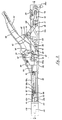
- the illustrated instrument shown generally in Fig. 1 comprises a housing 50 made up, as shown in Fig. 3, of a left-hand housing half 51 and a right-hand housing half 52.
- a jaw member 54 Detachably mounted at the forward end of the instrument housing 50, with the aid of a locking slide 53, is a jaw member 54 comprising respective forward and rear jaws 55 and 56 and a bight portion 57.
- Pivotally mounted on the rear portion of the housing 50 is an operating lever 58.
- the housing halves 51 and 52 are held together at the rear and at the central portions of the instrument, by means of pivoting latches 59 which will be described in detail below.
- the halves 51 and 52 are held together by the locking slide 53 as described hereinafter.
- the operating lever 58 is mounted on a pivot pin 60 the ends of which are located in the respective housing halves 51 and 52.
- a leaf spring 61 the free end 62 of which bears on the upper surface of the housing 50, biases the lever 58 to its open position as illustrated in Fig. 2.
- Extending downwardly from the central portion of the lever 58 is a toggle driving member 63, while depending from the forward end of the lever 58 is a member 64 on the lower end of which is pivotally mounted a pawl 65, having a downwardly and forwardly extending nose portion 66.
- the pawl 65 is biased downwardly by means of a spring 67.
- a toggle comprising a rear toggle link 68 and a forward toggle link 69, these links being interconnected by a toggle pin 70.
- This toggle pin carries a roller 161 for engagement by the toggle driving member 63 as described below.
- the rear toggle link 68 is connected by means of a pin 71 with a member 72 the rear end of which is connected, by means of a pin 73, with a pressure plate 74 fixed to the housing half 52 by means of a pin 75. The function of the plate 74 will be described below.
- the forward toggle link 69 is connected by means of a pivot pin 76 with the rearward end of a pusher member 77, the pin 76 passing through apertures 78 in the rear end of the pusher 77, which is shown in detail in Figs. 30 to 32.
- the pusher 77 is shaped and dimensioned for longitudinal sliding movement within the housing 50, and comprises a base 79 and a side wall 80.
- the apertures 78 are provided respectively in the side wall 80 and in a web 81, and an elongated slot 82 is provided in the base 79 of the pusher 77 for a purpose described below.
- the side wall 80 is extended upwardly by web 83 and a flange 83a extends inwardly from this extended portion of the side wall, for a purpose to be described below.
- a flange 84 extends laterally from this portion.
- the flange 84 and the underlying portion of the base 79 are similarly formed with slots 85 and inwardly directed lugs 86.
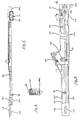
- T-bar extension 87 Mounted within the pusher 77 for longitudinals sliding movement relative thereto, is a T-bar extension 87, shown in detail in Figs. 27 to 29.
- a vertical hole 88 is provided, for the reception of a pin 89 (Fig. 2).
- This pin has an enlarged head and passes through the slot 82 in the base 79 of pusher 77, the head of the pin lying below the base 79, this pin thereby functioning to retain the T-bar extension 87 in assembly with the pusher 77, the slot 82 allowing for the necessary relative longitudinal movement of the T-bar extension 87.
- the T-bar extension 87 Forward of the pin 89, the T-bar extension 87 is provided with a portion 87a of increased height, to form a rearwardly facing shoulder 87b, the purpose of which will be explained below.
- the T-bar extension 87 is also provided near the middle thereof, with a raised portion containing a drilled hole 90.
- This raised portion is dimensioned for a neat fit beneath the flange 83 of the pusher 77, and is provided at its forward end with a shoulder 91 and 91a a which bear against the forward edges of the web 83 and the flange 83a to limit the rearward relative movement of the T-bar extension 87 with respect to the pusher 77.
- the hole 90 is tapped to receive the threaded rear end of a stop pin 92 comprising a body 92a and a forwardly extending spring guide portion 92b.
- the stop pin 92 is longitudinally adjustable, and is locked in its desired position by means of a lock nut 93 which bears against the surface of the T-bar extension 87 surrounding the threaded hole 90.
- a helical compression return spring 94 Surrounding the stop pin 92 is a helical compression return spring 94, the rearward end of which bears against the lock nut 93 and the forward end of which bears against a spring retainer 95 which is slidably mounted on the forward portion of the stop pin 92.
- a retaining nut 96 is screwed on to the threaded forward end of the stop pin 92.
- the forward end of the stop pin 92 passes through a slot 97 in a stop lug 98 (Figs. 4 and 5) which extends inwardly from the upper portion of the side wall of the right-hand housing half 52.
- the slot 97 is open at the left-hand extremity of the lug 98, so that the stop pin and spring assembly may be freed from the housing when the drive assembly is removed for cleaning.
- an upwardly extending lug 99 is separated by a slot 100 from a further upwardly extending lug 101 at the extreme forward end of the T-bar extension.
- a release lever 102 mounted within the rear portion of the housing 50.
- This lever which is best seen in Figs. 3 and 4, is pivotally fixed at its rear end to the right-hand housing half 52 by means of a pivot 103.
- a release lever button 104 passes through an arcuate slot 105 in the right-hand housing half 52.
- a depressed portion 102a which lies below the right-hand end of the toggle pin 70, which is extended beyond the toggle members towards the right-hand housing half 52.
- each housing half 51 and 52 is open at 107 to provide clearance for the toggle links 68 and 69 when that toggle is in its contracted condition as illustrated in Fig. 2.
- the latches 59 are illustrated in Figs. 33 and 34, and comprise a housing portion 108 the upper surface of which is concavely contoured for ease of operation with the thumb or finger, and depending donwwardly from the housing 108 there is provided a lug 109 which is provided with a drilled hole 110 for the reception of a pivot pin 111 (Fig. 6), one end of which is anchored in the right-hand housing half 52, and the other end of which is located in an aperture 112 in the left-hand housing half.
- the latch is provided with a pair of opposed downwardly extending lugs 113.
- each housing half 52 and 53 is apertured at 114 to allow for rotation of the latch on its pivot pin 111, and rearward of this aperture 114 there is provided a slot 115 for the reception of one of the lugs 113.
- These apertures 115 are provided in flanges 116 located below the upper surface of the respective housing half, by a distance corresponding to the base thickness of the latch housing 108.
- Adjacent the forward end of the left-hand housing half 51 is a vertical groove 117.
- the forward end of the right-hand housing half extends beyond that of the left-hand housing half in the region indicated at 118, this region having no bottom or upper wall.
- On the inner surface of this portion 118 there is provided a longitudinally directed key 119.
- the lugs 120 are located so that their rear edge abuts the front edge of the left-hand housing half 51, and extends laterally to an extent equal to the width of the left-hand housing half 51 at its forward end.
- the purpose of the key 119 and the grooves 121 is to enable locking assembly of the housing of the instrument with the head assembly, which will now be described.
- the head assembly of the instrument basically comprises the jaw member 54, a cartridge holder 122 and a T-bar 123.
- the T-bar is illustrated in Figs. 18 and 19 in a reversed position relative to the remainder of the components illustrated, in order that its locking features to be described below, may best be shown.
- the jaw sections of the jaw member 54 comprising the forward jaw 55, rear jaw 56 and bight portion 57 have already been described.
- the inner face of the forward jaw 55 is provided with an anvil receiving formation 124.
- An aperture 125 in the upper end of the forward jaw 55 receives the forward end of a tie pin 126, the rearward portion of which is passed through a cylindrical insert 127 which is held between flanges 128 which stand upwardly at the upper end of the rear jaw 56.
- a guide rail formation 129 is provided in the forward region of the upper surface of the bight portion 57, for the purpose of guiding and laterally locating the bottom of the cartridge holder 122.
- the upper and lower portions of the rear jaw 56 are joined by a web 130 provided with upper and lower flanges 131.
- the web 130 and the flanges 131 extend rearwardly from the jaw 56, and the web 130 is provided with a longitudinally orientated slot 132, this slot being dimensioned neatly to receive the key 119 provided on the forward portion 118 of the housing portion 52.
- the flanges 131 extend, in part, rearwardly for a short distance beyond the web 130, and vertically aligned slots 133 are provided at the left-hand side of the extending portions of these flanges 131.
- the upper and lower surfaces of the flanges 131 are relieved to provide grooves 134 which open to the rear edge of the flanges 131, in the region 135 where the flanges terminate co-extensively with the web 130.
- These grooves 134 are located so as to align with the grooves 121 in the forward end of the right-hand housing half 52, and the formations described are dimensioned such that when the jaw member 54 is engaged with the instrument housing, the key 119 enters the slot 132, the portion 135 abuts the forward end of the upper and lower walls of the right-hand housing half 52, and the rearmost edge of each flange 131 abuts the forward edge of the respective lug 120.
- the cartridge holder 122 is of generally T-shape in side elevation, comprising a pair of head flanges 136 provided with opposed grooves 137 for the reception of a staple cartridge in the manner known in the prior art.
- a stem 138 Extending rearwardly from the head flanges 136 is a stem 138 comprising upper and lower walls 139 and 140 respectively, left-hand side wall 141 and a longitudinally slotted right-hand side wall 142.
- the slot 143 in the right-hand side wall 142 extends throughout the length of that side wall and continues forwardly through portion of the right-hand head flange 136.
- a groove 144 which runs for the entire length of this side wall and continues for the entire longitudinal extent of the left-hand head flange 136.
- a vertical groove 145 On the outer surface of the left-hand side wall 141 forwardly of the rear thereof, there is provided a vertical groove 145, and the rear portion of the right-hand side wall is removed to allow the formation in the upper and lower walls 139 and 140, of a slot 146 and lug 146a (Fig. 16).
- These formations are dimensioned and located such that upon engagement of the head assembly with the instrument housing, the lugs 146 enter the slots 85 at the forward end of the pusher 77, and the lugs 86 at the forward end of the pusher 77 enter the slots 145.
- the T-bar 123 comprises a head 147 and a stem 148.
- the stem 148 is slotted at 149 and in this region a leaf spring 150 is provided, mounted at its rear end by means of a pin 151.
- the leaf spring 150 is biased outwardly of the slot 149 towards the right-hand side of the T-bar, and at its forward end there is mounted a locking pin 152.
- the locking pin 152 in the relaxed condition of the spring 150, stands proud of the right-hand side of the T-bar 123.
- the T-bar is, of course, mounted within the cartridge holder 122, with its head 147 between the head flanges 136 of the cartridge holder, and its stem 148 within the stem 138 of the cartridge holder.
- the pin 151 extends beyond the left-hand side of the T-bar and runs in the groove 144 in the left-hand side wall of the cartridge holder, while the locking pin 152 is free to lie within the slot 145 in the right-hand side wall 142 of the cartridge holder stem 138, and projecting outwardly beyond that side wall.
- lug 154 At the rearward end of the stem 148 there is provided a slot 153 and a downwardly directed lug 154, the lug 154 being located and dimensioned to engage with the slot 100 in the forward end of the T-bar extension 87 upon engagement of the head assembly with the instrument housing.
- the head assembly is completed by the locking slide 53, which is illustrated in Figs. 20 to 22.
- the locking slide 53 comprises a web 155 and a pair of flanges 156.
- the outer surface of the flanges 156 is provided with vertical grooves to assist the operator's grip, and each flange 156 is provided with opposed inwardly directed flanges 157.
- a resilient tongue 158 is formed at the rear end of the web 155, by means of diagonal slots 159, and the rear edge of the tongue 158 is provided with an inwardly directed detent 160.
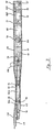
- Figs. 23 to 26 show the relationship between the components of the head assembly, in their assembled condition prior to engagement of the head assembly with the remainder of the instrument.
- the locking slide 53 embraces the stem 138 of the cartridge holder 122, with the flanges 157 engaged within the grooves 134, while the detent 160 is snapped into the groove 133.
- the locking pin 152 of the T-bar 123 extends through the slot 145 in the cartridge holder stem 138 to enter the slot 132 in the web 130, thereby restricting longitudinal movement of the T-bar in this condition.
- the head assembly is engaged with the instrument housing and actuating mechanism, with the T-bar 123 in its forwardmost position as defined by the engagement of the locking pin 152 with the forward end of the slot 132, by longitudinally aligning the housing and head assembly and moving the latter from the left such that the key 119 enters the slot 132.
- the T-bar extension 87 will engage with the T-bar 123 and the pusher 77 will engage with the cartridge holder 122 as previously described, and the key 119 will press the T-bar locking pin 152 inwardly and out of the slot 132, freeing the T-bar for operative longitudinal movement.
- the locking slide 53 is drawn on to the housing until the detent 160 engages the groove 117 in the left hand housing part 51. With the mounting of a cartridge and anvil in known manner, the instrument is then ready for use.
- Fig. 2 the mechanism is shown in its initial condition. Tissue proximation is first achieved by depressing the operating lever 58 so that the toggle drive member 63 contacts the toggle centre roller 161, driving this downwardly and thereby driving the pusher 77 forward by virtue of its engagement with the forward toggle pin 76. The cartridge holder 122 is thus moved to the staple firing position.
- the return spring 94 urges the T-bar extension rearwardly so that its shoulder 91 is urged against the pusher flange 83.
- the T-bar extension, and thus the T-bar, will therefore move forward with the pusher.
- the function of the pressure plate 74 is to absorb the effects of excessive tissue thickness or other variations which may effect the stapling force and staple formation.
- This member acts as a compression spring, allowing the entire drive mechanism to move backwards under excessive stapling force, and thereby increasing the effective tissue gap.
- the drive mechanism thus described has a further advantage which arises from the fact that the pusher, T-bar extension, toggle links, and pivot link 72 will remain interconnected when lifted away from the right-hand housing half 52 for cleaning, the pivot link 72 enabling this movement while retaining the connection of these components to the housing half.
- the mechanism may be cleaned between actuations with the minimum delay in re-assembly, such re-assembly requiring no special techniques and no tools.
- latches 59 to retain the housing halves together, in cooperation with the locking slide 53, also greatly simplifies the partial disassembly of the instrument for cleaning.
- head assemblies may be interchanged in the instrument of the present invention enables such head assemblies, comprising jaws, cartridge holder, T-bar and cartridge to be disposable, should this be desired.
Landscapes
- Health & Medical Sciences (AREA)
- Life Sciences & Earth Sciences (AREA)
- Surgery (AREA)
- Heart & Thoracic Surgery (AREA)
- Engineering & Computer Science (AREA)
- Biomedical Technology (AREA)
- Nuclear Medicine, Radiotherapy & Molecular Imaging (AREA)
- Medical Informatics (AREA)
- Molecular Biology (AREA)
- Animal Behavior & Ethology (AREA)
- General Health & Medical Sciences (AREA)
- Public Health (AREA)
- Veterinary Medicine (AREA)
- Surgical Instruments (AREA)
- Portable Nailing Machines And Staplers (AREA)
Claims (9)
Priority Applications (1)
| Application Number | Priority Date | Filing Date | Title |
|---|---|---|---|
| AT83900165T ATE40940T1 (de) | 1981-12-22 | 1982-12-22 | Chirurgisches nietinstrument. |
Applications Claiming Priority (4)
| Application Number | Priority Date | Filing Date | Title |
|---|---|---|---|
| AUPF205381 | 1981-12-22 | ||
| AU2053/81 | 1981-12-22 | ||
| AU4621/82 | 1982-06-28 | ||
| AUPF462182 | 1982-06-28 |
Related Child Applications (2)
| Application Number | Title | Priority Date | Filing Date |
|---|---|---|---|
| EP87202206A Division EP0273468A3 (fr) | 1981-12-22 | 1982-12-22 | Instrument d'agrafage chirurgical |
| EP87202206.6 Division-Into | 1987-11-12 |
Publications (3)
| Publication Number | Publication Date |
|---|---|
| EP0096694A1 EP0096694A1 (fr) | 1983-12-28 |
| EP0096694A4 EP0096694A4 (fr) | 1985-06-26 |
| EP0096694B1 true EP0096694B1 (fr) | 1989-03-01 |
Family
ID=25642516
Family Applications (2)
| Application Number | Title | Priority Date | Filing Date |
|---|---|---|---|
| EP19830900165 Expired EP0096694B1 (fr) | 1981-12-22 | 1982-12-22 | Instrument d'agrafage chirurgical |
| EP87202206A Withdrawn EP0273468A3 (fr) | 1981-12-22 | 1982-12-22 | Instrument d'agrafage chirurgical |
Family Applications After (1)
| Application Number | Title | Priority Date | Filing Date |
|---|---|---|---|
| EP87202206A Withdrawn EP0273468A3 (fr) | 1981-12-22 | 1982-12-22 | Instrument d'agrafage chirurgical |
Country Status (6)
| Country | Link |
|---|---|
| EP (2) | EP0096694B1 (fr) |
| JP (1) | JPS58502134A (fr) |
| CA (1) | CA1188183A (fr) |
| DE (1) | DE3279466D1 (fr) |
| NL (1) | NL8220482A (fr) |
| WO (1) | WO1983002247A1 (fr) |
Families Citing this family (266)
| Publication number | Priority date | Publication date | Assignee | Title |
|---|---|---|---|---|
| US4796793A (en) * | 1984-05-10 | 1989-01-10 | Ethicon, Inc. | Surgical stapler and methods |
| US4991764A (en) * | 1989-01-23 | 1991-02-12 | Edward Weck Incorporated | Surgical stapling instrument |
| US5470009A (en) * | 1990-12-06 | 1995-11-28 | United States Surgical Corporation | Surgical fastening apparatus with locking mechanism |
| CA2055943C (fr) * | 1990-12-06 | 2003-09-23 | Daniel P. Rodak | Dispositif de fixation chirurgicale avec mecanisme de verrouillage |
| WO1992010976A1 (fr) * | 1990-12-18 | 1992-07-09 | Minnesota Mining And Manufacturing Company | Dispositif de securite pour cartouche d'agrafeuse chirurgicale |
| US5413267A (en) * | 1991-05-14 | 1995-05-09 | United States Surgical Corporation | Surgical stapler with spent cartridge sensing and lockout means |
| AU671685B2 (en) * | 1991-05-14 | 1996-09-05 | United States Surgical Corporation | Surgical stapler with spent cartridge sensing and lockout means |
| US5137198A (en) * | 1991-05-16 | 1992-08-11 | Ethicon, Inc. | Fast closure device for linear surgical stapling instrument |
| US5366134A (en) * | 1991-10-18 | 1994-11-22 | United States Surgical Corporation | Surgical fastening apparatus |
| US5579978A (en) * | 1991-10-18 | 1996-12-03 | United States Surgical Corporation | Apparatus for applying surgical fasteners |
| CA2078794C (fr) * | 1991-10-18 | 1998-10-06 | Frank J. Viola | Dispositif de blocage pour instrument permettant d'appliquer des agrafes chirurgicales |
| ES2041610T3 (es) * | 1991-10-18 | 1997-05-16 | United States Surgical Corp | Aparato para aplicar broches de sujecion quirurgicos. |
| AU660712B2 (en) * | 1991-10-18 | 1995-07-06 | United States Surgical Corporation | Apparatus for applying surgical fasteners |
| US5240163A (en) * | 1991-10-30 | 1993-08-31 | American Cyanamid Company | Linear surgical stapling instrument |
| US5395034A (en) * | 1991-11-07 | 1995-03-07 | American Cyanamid Co. | Linear surgical stapling instrument |
| US5271543A (en) * | 1992-02-07 | 1993-12-21 | Ethicon, Inc. | Surgical anastomosis stapling instrument with flexible support shaft and anvil adjusting mechanism |
| US5514157A (en) | 1992-02-12 | 1996-05-07 | United States Surgical Corporation | Articulating endoscopic surgical apparatus |
| US5423471A (en) * | 1992-10-02 | 1995-06-13 | United States Surgical Corporation | Apparatus for applying two-part surgical fasteners in laparoscopic or endoscopic procedures |
| US5447265A (en) * | 1993-04-30 | 1995-09-05 | Minnesota Mining And Manufacturing Company | Laparoscopic surgical instrument with a mechanism for preventing its entry into the abdominal cavity once it is depleted and removed from the abdominal cavity |
| US6716232B1 (en) | 1993-04-30 | 2004-04-06 | United States Surgical Corporation | Surgical instrument having an articulated jaw structure and a detachable knife |
| US5470008A (en) * | 1993-12-20 | 1995-11-28 | United States Surgical Corporation | Apparatus for applying surgical fasteners |
| WO1995023557A1 (fr) * | 1994-03-01 | 1995-09-08 | United States Surgical Corporation | Agrafeuse chirurgicale pourvue d'un detecteur et d'un systeme de verrouillage au niveau de l'enclume |
| US5470007A (en) * | 1994-05-02 | 1995-11-28 | Minnesota Mining And Manufacturing Company | Laparoscopic stapler with overload sensor and interlock |
| US5489058A (en) * | 1994-05-02 | 1996-02-06 | Minnesota Mining And Manufacturing Company | Surgical stapler with mechanisms for reducing the firing force |
| US5735445A (en) * | 1995-03-07 | 1998-04-07 | United States Surgical Corporation | Surgical stapler |
| US5678748A (en) * | 1995-05-24 | 1997-10-21 | Vir Engineering | Surgical stapler with improved safety mechanism |
| US5706998A (en) * | 1995-07-17 | 1998-01-13 | United States Surgical Corporation | Surgical stapler with alignment pin locking mechanism |
| US5762256A (en) | 1995-08-28 | 1998-06-09 | United States Surgical Corporation | Surgical stapler |
| US5782396A (en) | 1995-08-28 | 1998-07-21 | United States Surgical Corporation | Surgical stapler |
| US5651491A (en) * | 1995-10-27 | 1997-07-29 | United States Surgical Corporation | Surgical stapler having interchangeable loading units |
| US5810240A (en) * | 1996-03-15 | 1998-09-22 | United States Surgical Corporation | Surgical fastener applying device |
| US6109500A (en) | 1996-10-04 | 2000-08-29 | United States Surgical Corporation | Lockout mechanism for a surgical stapler |
| US5865361A (en) | 1997-09-23 | 1999-02-02 | United States Surgical Corporation | Surgical stapling apparatus |
| US6817508B1 (en) | 2000-10-13 | 2004-11-16 | Tyco Healthcare Group, Lp | Surgical stapling device |
| US7407076B2 (en) | 2000-10-13 | 2008-08-05 | Tyco Healthcare Group Lp | Surgical stapling device |
| EP2347722B1 (fr) | 2001-10-05 | 2014-09-17 | Covidien LP | Dispositif d'agrafage chirurgical |
| US7726537B2 (en) | 2002-10-04 | 2010-06-01 | Tyco Healthcare Group Lp | Surgical stapler with universal articulation and tissue pre-clamp |
| JP4545589B2 (ja) | 2002-10-04 | 2010-09-15 | タイコ ヘルスケア グループ エルピー | 外科的ステープルデバイスのためのツールアセンブリ |
| DE60315846T2 (de) | 2002-10-04 | 2008-05-21 | Tyco Healthcare Group Lp, Norwalk | Zusammenbau von chirurgischem klammerwerkzeug |
| US9597078B2 (en) | 2003-04-29 | 2017-03-21 | Covidien Lp | Surgical stapling device with dissecting tip |
| US20040243151A1 (en) | 2003-04-29 | 2004-12-02 | Demmy Todd L. | Surgical stapling device with dissecting tip |
| US7494039B2 (en) | 2003-06-17 | 2009-02-24 | Tyco Healthcare Group Lp | Surgical stapling device |
| CA2724284C (fr) | 2003-06-17 | 2013-02-26 | Tyco Healthcare Group Lp | Dispositif chirurgical d'agrafage |
| US8770459B2 (en) | 2003-10-17 | 2014-07-08 | Covidien Lp | Surgical stapling device with independent tip rotation |
| US9138226B2 (en) | 2005-03-30 | 2015-09-22 | Covidien Lp | Cartridge assembly for a surgical stapling device |
| US7780055B2 (en) | 2005-04-06 | 2010-08-24 | Tyco Healthcare Group Lp | Loading unit having drive assembly locking mechanism |
| SG127831A1 (en) * | 2005-05-17 | 2006-12-29 | Ethicon Endo Surgery Inc | Surgical stapler having a plastic closure plate |
| CA2563147C (fr) | 2005-10-14 | 2014-09-23 | Tyco Healthcare Group Lp | Agrafeuse chirurgicale |
| US7552854B2 (en) | 2006-05-19 | 2009-06-30 | Applied Medical Resources Corporation | Surgical stapler with firing lock mechanism |
| US8708210B2 (en) | 2006-10-05 | 2014-04-29 | Covidien Lp | Method and force-limiting handle mechanism for a surgical instrument |
| US8584921B2 (en) | 2006-10-06 | 2013-11-19 | Covidien Lp | Surgical instrument with articulating tool assembly |
| US7866525B2 (en) | 2006-10-06 | 2011-01-11 | Tyco Healthcare Group Lp | Surgical instrument having a plastic surface |
| US8061576B2 (en) | 2007-08-31 | 2011-11-22 | Tyco Healthcare Group Lp | Surgical instrument |
| US7624902B2 (en) | 2007-08-31 | 2009-12-01 | Tyco Healthcare Group Lp | Surgical stapling apparatus |
| US7954685B2 (en) | 2007-11-06 | 2011-06-07 | Tyco Healthcare Group Lp | Articulation and firing force mechanisms |
| US8701959B2 (en) | 2008-06-06 | 2014-04-22 | Covidien Lp | Mechanically pivoting cartridge channel for surgical instrument |
| US7942303B2 (en) | 2008-06-06 | 2011-05-17 | Tyco Healthcare Group Lp | Knife lockout mechanisms for surgical instrument |
| US7789283B2 (en) | 2008-06-06 | 2010-09-07 | Tyco Healthcare Group Lp | Knife/firing rod connection for surgical instrument |
| US8215532B2 (en) | 2008-09-23 | 2012-07-10 | Tyco Healthcare Group Lp | Tissue stop for surgical instrument |
| US7988028B2 (en) | 2008-09-23 | 2011-08-02 | Tyco Healthcare Group Lp | Surgical instrument having an asymmetric dynamic clamping member |
| US8628544B2 (en) | 2008-09-23 | 2014-01-14 | Covidien Lp | Knife bar for surgical instrument |
| US7896214B2 (en) | 2008-09-23 | 2011-03-01 | Tyco Healthcare Group Lp | Tissue stop for surgical instrument |
| US8292154B2 (en) | 2009-04-16 | 2012-10-23 | Tyco Healthcare Group Lp | Surgical apparatus for applying tissue fasteners |
| US8127976B2 (en) | 2009-05-08 | 2012-03-06 | Tyco Healthcare Group Lp | Stapler cartridge and channel interlock |
| US8132706B2 (en) | 2009-06-05 | 2012-03-13 | Tyco Healthcare Group Lp | Surgical stapling apparatus having articulation mechanism |
| US8342378B2 (en) | 2009-08-17 | 2013-01-01 | Covidien Lp | One handed stapler |
| US8418907B2 (en) | 2009-11-05 | 2013-04-16 | Covidien Lp | Surgical stapler having cartridge with adjustable cam mechanism |
| US8348127B2 (en) | 2010-04-07 | 2013-01-08 | Covidien Lp | Surgical fastener applying apparatus |
| US8899461B2 (en) | 2010-10-01 | 2014-12-02 | Covidien Lp | Tissue stop for surgical instrument |
| US8308041B2 (en) | 2010-11-10 | 2012-11-13 | Tyco Healthcare Group Lp | Staple formed over the wire wound closure procedure |
| US9289209B2 (en) | 2011-06-09 | 2016-03-22 | Covidien Lp | Surgical fastener applying apparatus |
| US9451959B2 (en) | 2011-06-09 | 2016-09-27 | Covidien Lp | Surgical fastener applying apparatus |
| US9271728B2 (en) | 2011-06-09 | 2016-03-01 | Covidien Lp | Surgical fastener applying apparatus |
| US8763876B2 (en) | 2011-06-30 | 2014-07-01 | Covidien Lp | Surgical instrument and cartridge for use therewith |
| US20130012958A1 (en) | 2011-07-08 | 2013-01-10 | Stanislaw Marczyk | Surgical Device with Articulation and Wrist Rotation |
| US9724095B2 (en) | 2011-08-08 | 2017-08-08 | Covidien Lp | Surgical fastener applying apparatus |
| US9539007B2 (en) | 2011-08-08 | 2017-01-10 | Covidien Lp | Surgical fastener applying aparatus |
| US9155537B2 (en) | 2011-08-08 | 2015-10-13 | Covidien Lp | Surgical fastener applying apparatus |
| US9016539B2 (en) | 2011-10-25 | 2015-04-28 | Covidien Lp | Multi-use loading unit |
| US8740036B2 (en) | 2011-12-01 | 2014-06-03 | Covidien Lp | Surgical instrument with actuator spring arm |
| US10299815B2 (en) | 2012-01-19 | 2019-05-28 | Covidien Lp | Surgical instrument with clam releases mechanism |
| US8864010B2 (en) | 2012-01-20 | 2014-10-21 | Covidien Lp | Curved guide member for articulating instruments |
| US8979827B2 (en) | 2012-03-14 | 2015-03-17 | Covidien Lp | Surgical instrument with articulation mechanism |
| US9526497B2 (en) | 2012-05-07 | 2016-12-27 | Covidien Lp | Surgical instrument with articulation mechanism |
| CN102727269B (zh) * | 2012-06-15 | 2014-10-01 | 北京中法派尔特医疗设备有限公司 | 一种采用新型传动机构的直线切割缝合器 |
| US9232944B2 (en) | 2012-06-29 | 2016-01-12 | Covidien Lp | Surgical instrument and bushing |
| US9364217B2 (en) | 2012-10-16 | 2016-06-14 | Covidien Lp | In-situ loaded stapler |
| US9345480B2 (en) | 2013-01-18 | 2016-05-24 | Covidien Lp | Surgical instrument and cartridge members for use therewith |
| US9814463B2 (en) | 2013-03-13 | 2017-11-14 | Covidien Lp | Surgical stapling apparatus |
| US9629628B2 (en) | 2013-03-13 | 2017-04-25 | Covidien Lp | Surgical stapling apparatus |
| US9289211B2 (en) | 2013-03-13 | 2016-03-22 | Covidien Lp | Surgical stapling apparatus |
| US9717498B2 (en) | 2013-03-13 | 2017-08-01 | Covidien Lp | Surgical stapling apparatus |
| US12161322B2 (en) | 2013-03-13 | 2024-12-10 | Covidien Lp | Surgical stapling apparatus |
| CA2904678C (fr) | 2013-03-14 | 2022-07-12 | Applied Medical Resources Corporation | Agrafeuse chirurgicale pourvue de poches partielles |
| EP4129207B1 (fr) | 2013-03-15 | 2024-05-29 | Applied Medical Resources Corporation | Agrafeuse chirurgicale à mâchoire extensible |
| KR20250154547A (ko) | 2013-03-15 | 2025-10-28 | 어플라이드 메디컬 리소시스 코포레이션 | 회전가능 샤프트를 구비한 구동 메커니즘을 갖는 수술용 스테이플러 |
| US9510827B2 (en) | 2013-03-25 | 2016-12-06 | Covidien Lp | Micro surgical instrument and loading unit for use therewith |
| US9445810B2 (en) | 2013-06-12 | 2016-09-20 | Covidien Lp | Stapling device with grasping jaw mechanism |
| US9662108B2 (en) | 2013-08-30 | 2017-05-30 | Covidien Lp | Surgical stapling apparatus |
| WO2015065486A1 (fr) | 2013-11-04 | 2015-05-07 | Covidien Lp | Appareil d'application d'agrafes chirurgicales |
| EP3065649A1 (fr) | 2013-11-04 | 2016-09-14 | Covidien LP | Appareil d'application d'agrafes chirurgicales |
| EP3065647A1 (fr) | 2013-11-04 | 2016-09-14 | Covidien LP | Appareil d'application d'agrafes chirurgicales |
| US9867613B2 (en) | 2013-12-19 | 2018-01-16 | Covidien Lp | Surgical staples and end effectors for deploying the same |
| US9629627B2 (en) | 2014-01-28 | 2017-04-25 | Coviden Lp | Surgical apparatus |
| US9848874B2 (en) | 2014-02-14 | 2017-12-26 | Covidien Lp | Small diameter endoscopic stapler |
| US9757126B2 (en) | 2014-03-31 | 2017-09-12 | Covidien Lp | Surgical stapling apparatus with firing lockout mechanism |
| US9668733B2 (en) | 2014-04-21 | 2017-06-06 | Covidien Lp | Stapling device with features to prevent inadvertent firing of staples |
| US9861366B2 (en) | 2014-05-06 | 2018-01-09 | Covidien Lp | Ejecting assembly for a surgical stapler |
| WO2015174985A1 (fr) | 2014-05-15 | 2015-11-19 | Lp Covidien | Appareil d'application d'agrafe chirurgicale |
| ES2758511T3 (es) | 2014-06-11 | 2020-05-05 | Applied Med Resources | Grapadora quirúrgica con disparo circunferencial |
| KR20250027852A (ko) | 2014-09-15 | 2025-02-27 | 어플라이드 메디컬 리소시스 코포레이션 | 자동-조정 스테이플 높이를 가진 수술용 스테이플러 |
| US10039545B2 (en) | 2015-02-23 | 2018-08-07 | Covidien Lp | Double fire stapling |
| US10085749B2 (en) | 2015-02-26 | 2018-10-02 | Covidien Lp | Surgical apparatus with conductor strain relief |
| US10130367B2 (en) | 2015-02-26 | 2018-11-20 | Covidien Lp | Surgical apparatus |
| US9918717B2 (en) | 2015-03-18 | 2018-03-20 | Covidien Lp | Pivot mechanism for surgical device |
| US10463368B2 (en) | 2015-04-10 | 2019-11-05 | Covidien Lp | Endoscopic stapler |
| JP6420501B6 (ja) | 2015-05-08 | 2018-12-19 | ジャストライト サージカル,リミティド ライアビリティ カンパニー | 手術用ステープラ |
| AU2015396219B2 (en) | 2015-05-25 | 2020-03-05 | Covidien Lp | Small diameter surgical stapling device |
| US10349941B2 (en) | 2015-05-27 | 2019-07-16 | Covidien Lp | Multi-fire lead screw stapling device |
| US10172615B2 (en) | 2015-05-27 | 2019-01-08 | Covidien Lp | Multi-fire push rod stapling device |
| US10548599B2 (en) | 2015-07-20 | 2020-02-04 | Covidien Lp | Endoscopic stapler and staple |
| US9987012B2 (en) | 2015-07-21 | 2018-06-05 | Covidien Lp | Small diameter cartridge design for a surgical stapling instrument |
| US10064622B2 (en) | 2015-07-29 | 2018-09-04 | Covidien Lp | Surgical stapling loading unit with stroke counter and lockout |
| US10045782B2 (en) | 2015-07-30 | 2018-08-14 | Covidien Lp | Surgical stapling loading unit with stroke counter and lockout |
| AU2016304601B2 (en) | 2015-08-06 | 2020-10-22 | Applied Medical Resources Corporation | Surgical stapler having locking articulation joint |
| US10213204B2 (en) | 2015-10-02 | 2019-02-26 | Covidien Lp | Micro surgical instrument and loading unit for use therewith |
| US10772632B2 (en) | 2015-10-28 | 2020-09-15 | Covidien Lp | Surgical stapling device with triple leg staples |
| US10595864B2 (en) | 2015-11-24 | 2020-03-24 | Covidien Lp | Adapter assembly for interconnecting electromechanical surgical devices and surgical loading units, and surgical systems thereof |
| US10111660B2 (en) | 2015-12-03 | 2018-10-30 | Covidien Lp | Surgical stapler flexible distal tip |
| US10966717B2 (en) | 2016-01-07 | 2021-04-06 | Covidien Lp | Surgical fastener apparatus |
| US10660623B2 (en) | 2016-01-15 | 2020-05-26 | Covidien Lp | Centering mechanism for articulation joint |
| US10349937B2 (en) | 2016-02-10 | 2019-07-16 | Covidien Lp | Surgical stapler with articulation locking mechanism |
| US10420559B2 (en) | 2016-02-11 | 2019-09-24 | Covidien Lp | Surgical stapler with small diameter endoscopic portion |
| KR102624500B1 (ko) | 2016-04-12 | 2024-01-12 | 어플라이드 메디컬 리소시스 코포레이션 | 관절 메커니즘을 갖는 수술용 스테이플러 |
| AU2017250206B2 (en) | 2016-04-12 | 2022-03-24 | Applied Medical Resources Corporation | Surgical stapler having a powered handle |
| WO2017180785A1 (fr) | 2016-04-12 | 2017-10-19 | Applied Medical Resources Corporation | Ensemble tige de recharge pour agrafeuse chirurgicale |
| US10561419B2 (en) | 2016-05-04 | 2020-02-18 | Covidien Lp | Powered end effector assembly with pivotable channel |
| US11065022B2 (en) | 2016-05-17 | 2021-07-20 | Covidien Lp | Cutting member for a surgical instrument |
| EP3509525A4 (fr) * | 2016-09-09 | 2020-04-01 | Intuitive Surgical Operations Inc. | Détection et identification de rechargement d'agrafeuse |
| US10631857B2 (en) | 2016-11-04 | 2020-04-28 | Covidien Lp | Loading unit for surgical instruments with low profile pushers |
| US11642126B2 (en) | 2016-11-04 | 2023-05-09 | Covidien Lp | Surgical stapling apparatus with tissue pockets |
| US10492784B2 (en) | 2016-11-08 | 2019-12-03 | Covidien Lp | Surgical tool assembly with compact firing assembly |
| US10463371B2 (en) | 2016-11-29 | 2019-11-05 | Covidien Lp | Reload assembly with spent reload indicator |
| US10709901B2 (en) | 2017-01-05 | 2020-07-14 | Covidien Lp | Implantable fasteners, applicators, and methods for brachytherapy |
| US10952767B2 (en) | 2017-02-06 | 2021-03-23 | Covidien Lp | Connector clip for securing an introducer to a surgical fastener applying apparatus |
| US20180235618A1 (en) | 2017-02-22 | 2018-08-23 | Covidien Lp | Loading unit for surgical instruments with low profile pushers |
| US11350915B2 (en) | 2017-02-23 | 2022-06-07 | Covidien Lp | Surgical stapler with small diameter endoscopic portion |
| US10849621B2 (en) | 2017-02-23 | 2020-12-01 | Covidien Lp | Surgical stapler with small diameter endoscopic portion |
| US10299790B2 (en) | 2017-03-03 | 2019-05-28 | Covidien Lp | Adapter with centering mechanism for articulation joint |
| US10660641B2 (en) | 2017-03-16 | 2020-05-26 | Covidien Lp | Adapter with centering mechanism for articulation joint |
| US11324502B2 (en) | 2017-05-02 | 2022-05-10 | Covidien Lp | Surgical loading unit including an articulating end effector |
| US10603035B2 (en) | 2017-05-02 | 2020-03-31 | Covidien Lp | Surgical loading unit including an articulating end effector |
| US10524784B2 (en) | 2017-05-05 | 2020-01-07 | Covidien Lp | Surgical staples with expandable backspan |
| US10390826B2 (en) | 2017-05-08 | 2019-08-27 | Covidien Lp | Surgical stapling device with elongated tool assembly and methods of use |
| US10420551B2 (en) | 2017-05-30 | 2019-09-24 | Covidien Lp | Authentication and information system for reusable surgical instruments |
| US10478185B2 (en) | 2017-06-02 | 2019-11-19 | Covidien Lp | Tool assembly with minimal dead space |
| US10624636B2 (en) | 2017-08-23 | 2020-04-21 | Covidien Lp | Surgical stapling device with floating staple cartridge |
| US10806452B2 (en) | 2017-08-24 | 2020-10-20 | Covidien Lp | Loading unit for a surgical stapling instrument |
| US10925603B2 (en) | 2017-11-14 | 2021-02-23 | Covidien Lp | Reload with articulation stabilization system |
| US10863987B2 (en) | 2017-11-16 | 2020-12-15 | Covidien Lp | Surgical instrument with imaging device |
| US10945732B2 (en) | 2018-01-17 | 2021-03-16 | Covidien Lp | Surgical stapler with self-returning assembly |
| AU2019228507B2 (en) | 2018-02-27 | 2025-01-02 | Applied Medical Resources Corporation | Surgical stapler having a powered handle |
| CA3090020A1 (fr) | 2018-03-02 | 2019-09-06 | Covidien Lp | Instrument d'agrafage chirurgical |
| US10849622B2 (en) | 2018-06-21 | 2020-12-01 | Covidien Lp | Articulated stapling with fire lock |
| US10736631B2 (en) | 2018-08-07 | 2020-08-11 | Covidien Lp | End effector with staple cartridge ejector |
| US10849620B2 (en) | 2018-09-14 | 2020-12-01 | Covidien Lp | Connector mechanisms for surgical stapling instruments |
| US11510669B2 (en) | 2020-09-29 | 2022-11-29 | Covidien Lp | Hand-held surgical instruments |
| US11134952B2 (en) * | 2018-10-15 | 2021-10-05 | Cilag Gmbh International | Dual lever to reduce force to fire in circular surgical stapler |
| US11090051B2 (en) | 2018-10-23 | 2021-08-17 | Covidien Lp | Surgical stapling device with floating staple cartridge |
| US11197673B2 (en) | 2018-10-30 | 2021-12-14 | Covidien Lp | Surgical stapling instruments and end effector assemblies thereof |
| US10912563B2 (en) | 2019-01-02 | 2021-02-09 | Covidien Lp | Stapling device including tool assembly stabilizing member |
| CA3131187A1 (fr) | 2019-02-27 | 2020-09-03 | Applied Medical Resources Corporation | Instrument d'agrafage chirurgical ayant un mecanisme de verrouillage a deux positions |
| US11344297B2 (en) | 2019-02-28 | 2022-05-31 | Covidien Lp | Surgical stapling device with independently movable jaws |
| US11259808B2 (en) | 2019-03-13 | 2022-03-01 | Covidien Lp | Tool assemblies with a gap locking member |
| EP3946079A1 (fr) | 2019-03-29 | 2022-02-09 | Applied Medical Resources Corporation | Couvercle de recharge pour système d'agrafage chirurgical |
| US11284892B2 (en) | 2019-04-02 | 2022-03-29 | Covidien Lp | Loading unit and adapter with modified coupling assembly |
| US11284893B2 (en) | 2019-04-02 | 2022-03-29 | Covidien Lp | Stapling device with articulating tool assembly |
| US11241228B2 (en) | 2019-04-05 | 2022-02-08 | Covidien Lp | Surgical instrument including an adapter assembly and an articulating surgical loading unit |
| US11224424B2 (en) | 2019-08-02 | 2022-01-18 | Covidien Lp | Linear stapling device with vertically movable knife |
| US11406385B2 (en) | 2019-10-11 | 2022-08-09 | Covidien Lp | Stapling device with a gap locking member |
| US11123068B2 (en) | 2019-11-08 | 2021-09-21 | Covidien Lp | Surgical staple cartridge |
| US11534163B2 (en) | 2019-11-21 | 2022-12-27 | Covidien Lp | Surgical stapling instruments |
| US11395653B2 (en) | 2019-11-26 | 2022-07-26 | Covidien Lp | Surgical stapling device with impedance sensor |
| US11974743B2 (en) | 2019-12-02 | 2024-05-07 | Covidien Lp | Linear stapling device with a gap locking member |
| US11707274B2 (en) | 2019-12-06 | 2023-07-25 | Covidien Lp | Articulating mechanism for surgical instrument |
| US11109862B2 (en) | 2019-12-12 | 2021-09-07 | Covidien Lp | Surgical stapling device with flexible shaft |
| US12383260B2 (en) | 2019-12-13 | 2025-08-12 | Covidien Lp | Surgical stapler with universal tip reload |
| US11737747B2 (en) | 2019-12-17 | 2023-08-29 | Covidien Lp | Hand-held surgical instruments |
| JP2023510201A (ja) | 2019-12-31 | 2023-03-13 | アプライド メディカル リソーシーズ コーポレイション | 組織及び最大電流識別を用いる電気手術システム |
| US11278282B2 (en) | 2020-01-31 | 2022-03-22 | Covidien Lp | Stapling device with selective cutting |
| US11452524B2 (en) | 2020-01-31 | 2022-09-27 | Covidien Lp | Surgical stapling device with lockout |
| CN115052539B (zh) | 2020-02-03 | 2025-08-08 | 柯惠有限合伙公司 | 外科缝合装置 |
| EP4103078A4 (fr) | 2020-02-14 | 2024-03-06 | Covidien LP | Dispositif d'agrafage chirurgical |
| JP2023523507A (ja) | 2020-02-14 | 2023-06-06 | コヴィディエン リミテッド パートナーシップ | 外科用ステープルのための、かつ周壁に組織を把持するための隆起を有する、カートリッジホルダ |
| US11344301B2 (en) | 2020-03-02 | 2022-05-31 | Covidien Lp | Surgical stapling device with replaceable reload assembly |
| US11344302B2 (en) | 2020-03-05 | 2022-05-31 | Covidien Lp | Articulation mechanism for surgical stapling device |
| US11246593B2 (en) | 2020-03-06 | 2022-02-15 | Covidien Lp | Staple cartridge |
| US11707278B2 (en) | 2020-03-06 | 2023-07-25 | Covidien Lp | Surgical stapler tool assembly to minimize bleeding |
| US11357505B2 (en) | 2020-03-10 | 2022-06-14 | Covidien Lp | Surgical stapling apparatus with firing lockout mechanism |
| US11317911B2 (en) | 2020-03-10 | 2022-05-03 | Covidien Lp | Tool assembly with replaceable cartridge assembly |
| US11406383B2 (en) | 2020-03-17 | 2022-08-09 | Covidien Lp | Fire assisted powered EGIA handle |
| CN115315219B (zh) | 2020-03-24 | 2026-01-09 | 柯惠有限合伙公司 | 具有可替换钉仓的外科缝合装置 |
| US11426159B2 (en) | 2020-04-01 | 2022-08-30 | Covidien Lp | Sled detection device |
| US11331098B2 (en) | 2020-04-01 | 2022-05-17 | Covidien Lp | Sled detection device |
| US11504117B2 (en) | 2020-04-02 | 2022-11-22 | Covidien Lp | Hand-held surgical instruments |
| US11937794B2 (en) | 2020-05-11 | 2024-03-26 | Covidien Lp | Powered handle assembly for surgical devices |
| US11406387B2 (en) | 2020-05-12 | 2022-08-09 | Covidien Lp | Surgical stapling device with replaceable staple cartridge |
| US11191537B1 (en) | 2020-05-12 | 2021-12-07 | Covidien Lp | Stapling device with continuously parallel jaws |
| US11534167B2 (en) | 2020-05-28 | 2022-12-27 | Covidien Lp | Electrotaxis-conducive stapling |
| US11191538B1 (en) | 2020-06-08 | 2021-12-07 | Covidien Lp | Surgical stapling device with parallel jaw closure |
| US11844517B2 (en) | 2020-06-25 | 2023-12-19 | Covidien Lp | Linear stapling device with continuously parallel jaws |
| US11324500B2 (en) | 2020-06-30 | 2022-05-10 | Covidien Lp | Surgical stapling device |
| US12023027B2 (en) | 2020-07-02 | 2024-07-02 | Covidien Lp | Surgical stapling device with compressible staple cartridge |
| US12349902B2 (en) | 2020-07-09 | 2025-07-08 | Covidien Lp | Powered handle assembly for surgical devices |
| US11446028B2 (en) | 2020-07-09 | 2022-09-20 | Covidien Lp | Tool assembly with pivotable clamping beam |
| US11517305B2 (en) | 2020-07-09 | 2022-12-06 | Covidien Lp | Contoured staple pusher |
| EP4185215A4 (fr) | 2020-07-21 | 2024-04-03 | Covidien LP | Couvercle d'expédition pour cartouche d'agrafes |
| US11266402B2 (en) | 2020-07-30 | 2022-03-08 | Covidien Lp | Sensing curved tip for surgical stapling instruments |
| US11439392B2 (en) | 2020-08-03 | 2022-09-13 | Covidien Lp | Surgical stapling device and fastener for pathological exam |
| US11395654B2 (en) | 2020-08-07 | 2022-07-26 | Covidien Lp | Surgical stapling device with articulation braking assembly |
| US11602342B2 (en) | 2020-08-27 | 2023-03-14 | Covidien Lp | Surgical stapling device with laser probe |
| US11678878B2 (en) | 2020-09-16 | 2023-06-20 | Covidien Lp | Articulation mechanism for surgical stapling device |
| US11660092B2 (en) | 2020-09-29 | 2023-05-30 | Covidien Lp | Adapter for securing loading units to handle assemblies of surgical stapling instruments |
| US11406384B2 (en) | 2020-10-05 | 2022-08-09 | Covidien Lp | Stapling device with drive assembly stop member |
| US11576674B2 (en) | 2020-10-06 | 2023-02-14 | Covidien Lp | Surgical stapling device with articulation lock assembly |
| ES3034237T3 (en) | 2020-10-29 | 2025-08-14 | Applied Med Resources | Surgical stapler having a powered handle |
| KR20230096076A (ko) | 2020-10-29 | 2023-06-29 | 어플라이드 메디컬 리소시스 코포레이션 | 수술용 기구에 대한 재료 조합들 및 프로세싱 방법들 |
| AU2021368128A1 (en) | 2020-10-29 | 2023-06-01 | Applied Medical Resources Corporation | Actuation shaft retention mechanism for surgical stapler |
| US11890007B2 (en) | 2020-11-18 | 2024-02-06 | Covidien Lp | Stapling device with flex cable and tensioning mechanism |
| US11737774B2 (en) | 2020-12-04 | 2023-08-29 | Covidien Lp | Surgical instrument with articulation assembly |
| US11819200B2 (en) | 2020-12-15 | 2023-11-21 | Covidien Lp | Surgical instrument with articulation assembly |
| US11553914B2 (en) | 2020-12-22 | 2023-01-17 | Covidien Lp | Surgical stapling device with parallel jaw closure |
| US12336708B2 (en) | 2020-12-23 | 2025-06-24 | Covidien Lp | Surgical instrument including a decoupling mechanism |
| US11759206B2 (en) | 2021-01-05 | 2023-09-19 | Covidien Lp | Surgical stapling device with firing lockout mechanism |
| US11744582B2 (en) | 2021-01-05 | 2023-09-05 | Covidien Lp | Surgical stapling device with firing lockout mechanism |
| KR20230129523A (ko) | 2021-01-14 | 2023-09-08 | 어플라이드 메디컬 리소시스 코포레이션 | 샤프트 인식 메커니즘을 갖는 수술용 스테이플러 |
| US11759207B2 (en) | 2021-01-27 | 2023-09-19 | Covidien Lp | Surgical stapling apparatus with adjustable height clamping member |
| US11517313B2 (en) | 2021-01-27 | 2022-12-06 | Covidien Lp | Surgical stapling device with laminated drive member |
| US11717300B2 (en) | 2021-03-11 | 2023-08-08 | Covidien Lp | Surgical stapling apparatus with integrated visualization |
| US11974750B2 (en) | 2021-03-26 | 2024-05-07 | Covidien Lp | Surgical staple cartridge |
| US11666330B2 (en) | 2021-04-05 | 2023-06-06 | Covidien Lp | Surgical stapling device with lockout mechanism |
| US11576670B2 (en) | 2021-05-06 | 2023-02-14 | Covidien Lp | Surgical stapling device with optimized drive assembly |
| US11812956B2 (en) | 2021-05-18 | 2023-11-14 | Covidien Lp | Dual firing radial stapling device |
| US11696755B2 (en) | 2021-05-19 | 2023-07-11 | Covidien Lp | Surgical stapling device with reload assembly removal lockout |
| US12414770B2 (en) | 2021-05-21 | 2025-09-16 | Covidien Lp | Articulation assembly for a surgical device |
| US11771423B2 (en) | 2021-05-25 | 2023-10-03 | Covidien Lp | Powered stapling device with manual retraction |
| US11510673B1 (en) | 2021-05-25 | 2022-11-29 | Covidien Lp | Powered stapling device with manual retraction |
| US11701119B2 (en) | 2021-05-26 | 2023-07-18 | Covidien Lp | Powered stapling device with rack release |
| US11576675B2 (en) | 2021-06-07 | 2023-02-14 | Covidien Lp | Staple cartridge with knife |
| US11707275B2 (en) | 2021-06-29 | 2023-07-25 | Covidien Lp | Asymmetrical surgical stapling device |
| US11617579B2 (en) | 2021-06-29 | 2023-04-04 | Covidien Lp | Ultra low profile surgical stapling instrument for tissue resections |
| US11602344B2 (en) | 2021-06-30 | 2023-03-14 | Covidien Lp | Surgical stapling apparatus with firing lockout assembly |
| US11540831B1 (en) | 2021-08-12 | 2023-01-03 | Covidien Lp | Staple cartridge with actuation sled detection |
| US11779334B2 (en) | 2021-08-19 | 2023-10-10 | Covidien Lp | Surgical stapling device including a manual retraction assembly |
| US11707277B2 (en) | 2021-08-20 | 2023-07-25 | Covidien Lp | Articulating surgical stapling apparatus with pivotable knife bar guide assembly |
| US11576671B1 (en) | 2021-08-20 | 2023-02-14 | Covidien Lp | Small diameter linear surgical stapling apparatus |
| US12023028B2 (en) | 2021-08-20 | 2024-07-02 | Covidien Lp | Articulating surgical stapling apparatus with pivotable knife bar guide assembly |
| US11864761B2 (en) | 2021-09-14 | 2024-01-09 | Covidien Lp | Surgical instrument with illumination mechanism |
| US11653922B2 (en) | 2021-09-29 | 2023-05-23 | Covidien Lp | Surgical stapling device with firing lockout mechanism |
| US11660094B2 (en) | 2021-09-29 | 2023-05-30 | Covidien Lp | Surgical fastening instrument with two-part surgical fasteners |
| US11849949B2 (en) | 2021-09-30 | 2023-12-26 | Covidien Lp | Surgical stapling device with firing lockout member |
| US12035909B2 (en) | 2021-10-13 | 2024-07-16 | Covidien Lp | Surgical stapling device with firing lockout mechanism |
| US12268389B2 (en) | 2021-11-12 | 2025-04-08 | Covidien Lp | Surgical stapling device with firing lockout |
| US12137905B2 (en) | 2022-05-16 | 2024-11-12 | Covidien Lp | Gas-powered continuous feed surgical fastening device |
| US12193666B2 (en) | 2022-05-27 | 2025-01-14 | Covidien Lp | Replaceable staple cartridge with retractable knife |
| US12502173B2 (en) | 2023-05-09 | 2025-12-23 | Covidien Lp | Surgical stapling device with jaws that pivot between an open position and a clamped position |
Family Cites Families (11)
| Publication number | Priority date | Publication date | Assignee | Title |
|---|---|---|---|---|
| GB487085A (en) * | 1936-03-20 | 1938-06-15 | Boston Wire Stitcher Co | Improvements in or relating to fastener-applying devices |
| US3269630A (en) * | 1964-04-30 | 1966-08-30 | Fleischer Harry | Stapling instrument |
| US3315863A (en) * | 1965-07-06 | 1967-04-25 | United States Surgical Corp | Medical instrument |
| US3490675A (en) * | 1966-10-10 | 1970-01-20 | United States Surgical Corp | Instrument for placing lateral gastrointestinal anastomoses |
| SU506963A1 (ru) * | 1973-07-26 | 1976-08-25 | Всесоюзный Научно-Исследовательский И Испытательный Институт Медицинской Техники Министерства Здравоохранения Ссср | Хирургический сшивающий аппарат |
| IT7622106U1 (it) * | 1976-09-15 | 1978-03-15 | Monacelli Umberto | Apparecchio adattabile per l'infissione di elementi di fissaggio, quali chiodi e punti metallici, in posti di difficile accesso. |
| US4296751A (en) * | 1979-08-02 | 1981-10-27 | Blake Joseph W Iii | Surgical device |
| US4331277A (en) * | 1980-05-23 | 1982-05-25 | United States Surgical Corporation | Self-contained gas powered surgical stapler |
| WO1982000968A1 (fr) * | 1980-09-18 | 1982-04-01 | Dippert M | Mecanisme d'entrainement d'une agrafeuse chirurgicale |
| US4354628A (en) * | 1980-09-29 | 1982-10-19 | United States Surgical Corporation | Surgical stapler apparatus having pivotally related staple holder and anvil |
| US4383634A (en) * | 1981-05-26 | 1983-05-17 | United States Surgical Corporation | Surgical stapler apparatus with pivotally mounted actuator assemblies |
-
1982
- 1982-12-22 JP JP58500256A patent/JPS58502134A/ja active Pending
- 1982-12-22 CA CA000418358A patent/CA1188183A/fr not_active Expired
- 1982-12-22 EP EP19830900165 patent/EP0096694B1/fr not_active Expired
- 1982-12-22 DE DE8383900165T patent/DE3279466D1/de not_active Expired
- 1982-12-22 NL NL8220482A patent/NL8220482A/nl unknown
- 1982-12-22 WO PCT/AU1982/000217 patent/WO1983002247A1/fr not_active Ceased
- 1982-12-22 EP EP87202206A patent/EP0273468A3/fr not_active Withdrawn
Also Published As
| Publication number | Publication date |
|---|---|
| NL8220482A (nl) | 1983-11-01 |
| JPS58502134A (ja) | 1983-12-15 |
| DE3279466D1 (en) | 1989-04-06 |
| WO1983002247A1 (fr) | 1983-07-07 |
| EP0273468A3 (fr) | 1988-08-31 |
| EP0273468A2 (fr) | 1988-07-06 |
| CA1188183A (fr) | 1985-06-04 |
| EP0096694A1 (fr) | 1983-12-28 |
| EP0096694A4 (fr) | 1985-06-26 |
Similar Documents
| Publication | Publication Date | Title |
|---|---|---|
| EP0273468A2 (fr) | Instrument d'agrafage chirurgical | |
| US20250387932A1 (en) | Out-the-front knife | |
| US4523695A (en) | Surgical stapler | |
| US5009134A (en) | Quick-action bar clamp | |
| KR0142018B1 (ko) | 체결용 공구 | |
| US5071052A (en) | Surgical fastening apparatus with activation lockout | |
| AU649008B2 (en) | Quick action bar clamp | |
| EP1590130B1 (fr) | Outil d'entrainement de dispositif de fixation avec element de contact mobile, et procede pour echanger des elements de contact | |
| US5065929A (en) | Surgical stapler with locking means | |
| US4202480A (en) | Stapler including means for preventing double feeding of staples | |
| GB2068817A (en) | Surgical instruments | |
| GB2073022A (en) | Clip stop for surgical clip applying device | |
| CA2008415A1 (fr) | Agrafeuse chirurgicale | |
| US11931030B2 (en) | Stapling device with cartridge assembly with alignment pins | |
| JPH072313B2 (ja) | 特にステ−プル用の動力作動式打込み機 | |
| CN109662744B (zh) | 吻合器 | |
| US4477007A (en) | Stapler with intermediate latching mechanism | |
| AU564692B2 (en) | Surgical stapling instrument | |
| AU1100183A (en) | Surgical stapling instrument | |
| GB2273073A (en) | Quick action bar clamp | |
| JPH0312431Y2 (fr) | ||
| US20250000509A1 (en) | Stapling device including a retractable knife assembly | |
| CA1327928C (fr) | Appareil de fixation chirurgicale avec verrouillage | |
| CN119679469A (zh) | 施夹钳 | |
| CA1148053A (fr) | Instrument pour appliquer des agrafes chirurgicales |
Legal Events
| Date | Code | Title | Description |
|---|---|---|---|
| PUAI | Public reference made under article 153(3) epc to a published international application that has entered the european phase |
Free format text: ORIGINAL CODE: 0009012 |
|
| AK | Designated contracting states |
Designated state(s): AT CH DE FR GB LI SE |
|
| 17P | Request for examination filed |
Effective date: 19831230 |
|
| 17Q | First examination report despatched |
Effective date: 19870122 |
|
| GRAA | (expected) grant |
Free format text: ORIGINAL CODE: 0009210 |
|
| AK | Designated contracting states |
Kind code of ref document: B1 Designated state(s): AT CH DE FR GB LI SE |
|
| REF | Corresponds to: |
Ref document number: 40940 Country of ref document: AT Date of ref document: 19890315 Kind code of ref document: T |
|
| REF | Corresponds to: |
Ref document number: 3279466 Country of ref document: DE Date of ref document: 19890406 |
|
| ET | Fr: translation filed | ||
| PG25 | Lapsed in a contracting state [announced via postgrant information from national office to epo] |
Ref country code: AT Effective date: 19891222 |
|
| PG25 | Lapsed in a contracting state [announced via postgrant information from national office to epo] |
Ref country code: LI Effective date: 19891231 Ref country code: CH Effective date: 19891231 |
|
| PLBE | No opposition filed within time limit |
Free format text: ORIGINAL CODE: 0009261 |
|
| STAA | Information on the status of an ep patent application or granted ep patent |
Free format text: STATUS: NO OPPOSITION FILED WITHIN TIME LIMIT |
|
| 26N | No opposition filed | ||
| REG | Reference to a national code |
Ref country code: CH Ref legal event code: PL |
|
| REG | Reference to a national code |
Ref country code: GB Ref legal event code: 732 |
|
| REG | Reference to a national code |
Ref country code: FR Ref legal event code: TP |
|
| EAL | Se: european patent in force in sweden |
Ref document number: 83900165.8 |
|
| REG | Reference to a national code |
Ref country code: GB Ref legal event code: 732E |
|
| REG | Reference to a national code |
Ref country code: FR Ref legal event code: TP Free format text: CORRECTION |
|
| PGFP | Annual fee paid to national office [announced via postgrant information from national office to epo] |
Ref country code: FR Payment date: 20011130 Year of fee payment: 20 |
|
| PGFP | Annual fee paid to national office [announced via postgrant information from national office to epo] |
Ref country code: SE Payment date: 20011203 Year of fee payment: 20 |
|
| PGFP | Annual fee paid to national office [announced via postgrant information from national office to epo] |
Ref country code: GB Payment date: 20011204 Year of fee payment: 20 Ref country code: DE Payment date: 20011204 Year of fee payment: 20 |
|
| REG | Reference to a national code |
Ref country code: GB Ref legal event code: IF02 |
|
| PG25 | Lapsed in a contracting state [announced via postgrant information from national office to epo] |
Ref country code: GB Free format text: LAPSE BECAUSE OF EXPIRATION OF PROTECTION Effective date: 20021221 |
|
| REG | Reference to a national code |
Ref country code: GB Ref legal event code: PE20 Effective date: 20021221 |
|
| EUG | Se: european patent has lapsed |