EP0096778A2 - Mikrofon - Google Patents
Mikrofon Download PDFInfo
- Publication number
- EP0096778A2 EP0096778A2 EP83105247A EP83105247A EP0096778A2 EP 0096778 A2 EP0096778 A2 EP 0096778A2 EP 83105247 A EP83105247 A EP 83105247A EP 83105247 A EP83105247 A EP 83105247A EP 0096778 A2 EP0096778 A2 EP 0096778A2
- Authority
- EP
- European Patent Office
- Prior art keywords
- microphone
- voltage
- amplifier
- converter
- output
- Prior art date
- Legal status (The legal status is an assumption and is not a legal conclusion. Google has not performed a legal analysis and makes no representation as to the accuracy of the status listed.)
- Granted
Links
Images


Classifications
-
- H—ELECTRICITY
- H04—ELECTRIC COMMUNICATION TECHNIQUE
- H04R—LOUDSPEAKERS, MICROPHONES, GRAMOPHONE PICK-UPS OR LIKE ACOUSTIC ELECTROMECHANICAL TRANSDUCERS; ELECTRIC HEARING AIDS; PUBLIC ADDRESS SYSTEMS
- H04R3/00—Circuits for transducers
-
- H—ELECTRICITY
- H04—ELECTRIC COMMUNICATION TECHNIQUE
- H04R—LOUDSPEAKERS, MICROPHONES, GRAMOPHONE PICK-UPS OR LIKE ACOUSTIC ELECTROMECHANICAL TRANSDUCERS; ELECTRIC HEARING AIDS; PUBLIC ADDRESS SYSTEMS
- H04R19/00—Electrostatic transducers
- H04R19/04—Microphones
Definitions
- the invention relates to a microphone according to the preamble of claim 1.
- a microphone is e.g. known as U89 from Georg Neumann, Berlin.
- a phantom circuit is frequently used to power a microphone, in which the supply voltage is connected to the two wires of the symmetrical LF connection between the microphone and the consumer via two resistors of the same size, for example 6.8 kOhm at 48 volts.
- this impedance matching takes place by means of a transformer (up to 10: 1 reduction) in the signal path of the microphone between its amplifier and the microphone output.
- transformerless microphones In recent times, efforts to do without transformers in LF signal processing have increased, for example to avoid possible signal distortions.
- transformerless microphones accept an impedance mismatch, which leads to a restriction of the dynamic range that is possible per se.
- the object of the invention is to provide a microphone of the type mentioned at the outset which enables impedance matching while avoiding a transformer in the LF signal path.
- the invention is based on the idea of moving the necessary impedance matching from the LF signal path into the power supply line of the amplifier built into the microphone.
- an operating voltage adapted to the load for the amplifier is obtained by means of a DC voltage converter.
- the existing DC-DC converter also allows the generation of different voltages for the microphone capsule, as are required to achieve different directional characteristics.
- the DC-DC converter is designed in the form of a flyback converter,
- the dash-dotted circuit block 1 indicates the microphone and the dash-dotted circuit block 2 the power supply source.
- the microphone 1 is connected via a 2-wire NF cable 3 to the power supply source 2, which is the NF consumer Z L as the terminating impedance of the cable 3 and a DC voltage source B of, for example, +48 V, the positive pole of which is connected to each wire of the cable 3 via resistors R of the same size (for example 6.8 kOhm).
- This phantom power supply for the microphone 1 represents the most common case of the power supply for the microphone 1, but the invention is not restricted to this type of power supply.
- the microphone 1 includes in its LF signal path a microphone capsule 30 which is connected to the input of a microphone amplifier 20 via a series capacitor 40, which is used to separate the DC component in the output current of the capsule 30.
- a microphone capsule 30 Connected to the output terminals 21, 22 of the amplifier are, on the one hand, the wires of the cable 3 and, on the other hand, the input terminals of a coupling device 50, which couples out the supply voltage fed from the source B via the wires of the cable 3 and feeds it to the input 11 of a DC voltage converter 10.
- a coupling device 50 which couples out the supply voltage fed from the source B via the wires of the cable 3 and feeds it to the input 11 of a DC voltage converter 10.
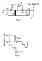
- 2 and 3 DC voltage converter 10 shown in more detail works, for example, as a flyback converter, which has a pulse-width-controlled switching element, in the blocking phase of which the g output voltages U B1 and U B2 are generated at the output terminals 13 and 14 of the converter 10, respectively.
- the output voltage U B1 at the output terminal 13 is fed via a series resistor 60 to the capsule 30 for its voltage supply.
- the output voltage U B2 at the output terminal 14 serves as the operating voltage for the amplifier 20.
- the generation of the voltages U B1 and U B2 by means of the coupling device 50 and the DC-DC converter 10 allows the microphone 1 to be optimally adapted to the available power of the source B, without the need for a transformer at the microphone output. As a result, the entire dynamic range of the microphone 1 which is possible per se can be used for the first time in the case of a transformerless microphone.
- the DC-DC converter 10 can preferably be designed as a flyback converter, the primary winding w1 of which is connected to the one winding end at the converter input 11 and to the other winding end via a switching element Tr, in the example shown a switching transistor, with a reference potential (ground) is.
- the tax input of the switching element Tr is connected to the output 17 of a controller 15, the input 16 of which is connected to the output terminal 14 of the converter 10, so that the voltage U B2 is supplied to the controller 15 as the actual value.
- the controller 15 controls the opening and closing times of the switching element Tr in accordance with a pulse width regulation, so that the energy stored in the primary winding w1 and taken from the secondary windings w21, w22, w23 in each cycle period also in the event of fluctuations in the power supply from the source B (FIG. 1 ) is kept at the desired constant value.
- the primary winding w1 is coupled to two or three secondary windings w21, w22 and w23, each of which feeds an output rectifier Dl, C1 or D2, C2 or D3, C3.
- the output rectifier D1, C1 generates the output voltage U B2 at the output terminal 14, while the output rectifier D2, C2 generates the output voltage U B1 at the output terminal 13.
- the third output rectifier D3, C3, shown in broken lines in FIG. 2, can be provided, if necessary, for generating a further output voltage U B3 , for example in order to switch the directional characteristic of the microphone capsule 30 (FIG. 1) in a known manner.
- the time profile of the blocking voltage U block shown in FIG. 4 with a solid line is advantageously generated on the secondary windings w21 and w22.
- the larger output voltage U B1 at the output terminal 13 is obtained from the first voltage peak of the blocking voltage U block before the blocking voltage U s p err assumes the value U B2 at the output terminal 14.
- a time window of the width ⁇ T (FIG. 4) is used to suppress the first voltage peak, which is implemented by a time delay device arranged between the secondary winding w21 and the output rectifier D1, C1.
- this time delay device consists of a series inductance L (FIG. 2).
- a longitudinal thyristor Th (FIG. 3) can be provided, which is controlled by a comparator 12.
- the comparator 12 compares the voltage at the anode of the thyristor Th with a reference voltage U ref (corresponds to the amount U B1 in FIG. 3) and blocks, for example, the thyristor Th until the voltage at its anode reaches the value of the reference voltage U ref , that is during a time interval ⁇ T.
- Both voltages U B1 and U B2 can be obtained both from a common winding w2 and from separate windings w21 and w22.
- the voltage U B1 is brought by means of the comparator 12 to the desired value, ref either by limiting the voltage U s p he r through the diodes ZD and D4 (Fig. 2) or by comparison with U while the voltage U B2 in a known manner is kept constant by the action of the controller 15.
Landscapes
- Physics & Mathematics (AREA)
- Engineering & Computer Science (AREA)
- Acoustics & Sound (AREA)
- Signal Processing (AREA)
- Dc-Dc Converters (AREA)
- Amplifiers (AREA)
- Measuring Pulse, Heart Rate, Blood Pressure Or Blood Flow (AREA)
- Electrostatic, Electromagnetic, Magneto- Strictive, And Variable-Resistance Transducers (AREA)
Abstract
Description
- Die Erfindung bezieht sich auf ein Mikrofon gemäß dem Oberbegriff des Anspruchs 1. Ein derartiges Mikrofon ist z.B. unter der Bezeichnung U89 der Fa. Georg Neumann, Berlin, bekannt.
- Zur Stromversorgung eines Mikrofons wird häufig eine Phantomschaltung verwendet, bei der die Versorgungsspannung über zwei gleich große Widerstände, z.B. 6,8 kOhm bei 48 Volt, auf die beiden Adern der symmetrischen NF-Verbindung zwischen Mikrofon und Verbraucher aufgeschaltet ist. Der dadurch bedingte, relativ hohe Innenwiderstand der Stromversorgung sowie die maximal zulässige Stromentnahme begrenzen die dem Mikrofon zur Verfügung stehende Leistung, mit der Folge, daß eine Impedanzanpassung an den standardisierten minimalen Belastungswiderstand (1 kOhm) des Mikrofons erforderlich ist. Diese Impedanzanpassung erfolgt bei dem eingangs erwähnten, bekannten Mikrofon mittels eines Transformators (bis zu 10:1 Untersetzung) im Signalweg des Mikrofons zwischen dessen Verstärker und dem Mikrofon-Ausgang.
- In jüngster Zeit mehren sich die Bestrebungen, auf Transformatoren in der NF-Signalverarbeitung zu verzichten, beispielsweise, um mögliche Signalverzerrungen zu vermeiden. Bekannte, transformatorlose Mikrofone nehmen jedoch eine Impedanzfehlanpassung in Kauf, was zu einer Einschränkung des an sich möglichen Dynamikumfangs führt.
- Die Aufgabe der Erfindung besteht demgegenüber darin, ein Mikrofon der eingangs erwähnten Art zu schaffen, welches eine Impedanzanpassung unter Vermeidung eines Transformators im NF-Signalweg ermöglicht.
- Diese Aufgabe wird erfindungsgemäß durch die kennzeichnenden Merkmale des Anspruchs 1 gelöst.
- Vorteilhafte Weiterbildungen und Ausgestaltungen des Mikrofons nach Anspruch 1 ergeben sich aus den Unteransprüchen.
- Die Erfindung beruht auf der Überlegung, die nötige Impedanzanpassung aus dem NF-Signalweg in die Stromversorgungszuführung des im Mikrofon eingebauten Verstärkers zu verlegen. Hierzu wird mittels eines Gleichspannungswandlers eine belastungsgerecht angepaßte Betriebsspannung für den Verstärker gewonnen. Auf diese Weise lassen sich im Vergleich zu dem eingangs erwähnten Stand der Technik nicht nur Verbesserungen hinsichtlich der Signalqualität, sondern auch eine Erhöhung der oberen Aussteuerungsgrenze erzielen, da mittels des Gleichspannungswandlers eine annähernd ideale Ausregel-ung von Schwankungen der Stromversorgung erfolgt und eine optimale Auslegung der im Mikrofon eingebauten Verstärkerschaltungen auf niedrigere Betriebsspannungen möglich ist.
- Der vorhandene Gleichspannungswandler gestattet gleichzeitig die Erzeugung unterschiedlicher Spannungen für die Mikrofonkapsel, wie sie zur Erzielung unterschiedlicher Richtcharakteristikenerforderlich sind. Bei Ausbildung des Gleichspannungswandlers in Form eines Sperrwandlers lassen sich durch
- Verwendung einer Verzögerungseinrichtung zum zeitverzögerten Zuführen der in der Sperrphase auftretenden Spannung an eine Gleichrichtereinrichtung mit besonders hohem Wirkungsgrad zwei erheblich voneinander abweichende Gleichspannungen mittels ein und derselben Speicherinduktivität erzielen.
- Die Erfindung wird nachstehend anhand von Ausführungsbeispielen in den Zeichnungen näher erläutert. Es zeigt:
- Fig. 1 ein elektrisches Prinzipschaltbild eines erfindungsgemäß ausgebildeten Mikrofons mit dessen Stromversorgungsquelle;
- Fig. 2 ein elektrisches Schaltbild eines in dem Mikrofon nach Fig. 1 eingebauten Gleichspannungswandlers zum Erzeugen einer belastungsgerecht angepaßten Betriebsspannung für den Mikrofon-Verstärker;
- Fig. 3 ein elektrisches Schaltbild einer gegenüber Fig. 2 abweichenden Einrichtung zum zeitverzögerten Zuführen der in der Sperrphase des Gleichspannungswandlers nach Fig. 2 auftretenden Spannung an eine Ausgangsgleichrichterschaltung, und
- Fig. 4 ein Zeitdiagramm für den Verlauf der in der Sperrphase des Gleichspannungswandlers nach Fig. 2 auftretenden Sperrspannung Usperr.
- Bei der in Fig. 1 dargestellten elektrischen Prinzipschaltung eines erfindungsgemäßen Mikrofons mit dessen Stromversorgungsquelle sind mit dem strichpunktierten Schaltungsblock 1 das Mikrofon und mit dem strichpunktierten Schaltungsblock 2 die Stromversorgungsquelle angedeutet. Das Mikrofon 1 ist über ein 2-adriges NF-Kabel 3 mit der Stromversorgungsquelle 2 verbunden, welche den NF-Verbraucher ZL als Abschlußimpedanz des Kabels 3 und eine Gleichspannungsquelle B von beispielsweise +48 V enthält, deren Pluspol mit jeder Ader des Kabels 3 über gleich große Widerstände R (z.B. 6,8 kOhm) verbunden ist. Diese Phantomspeisung des Mikrofons 1 stellt den häufigsten Fall der Stromversorgung für das Mikrofon 1 dar, ohne daß jedoch die Erfindung auf diese Stromversorgungsart beschränkt ist.
- Das Mikrofon1 umfaßt in seinem NF-Signalweg eine Mikrofonkapsel 30, die über einen Längskondensator 40, der zur Abtrennung des Gleichstromanteils im Ausgangsstrom der Kapsel 30 dient, mit dem Eingang eines Mikrofonv erstärkers 20 verbunden ist. An die Ausgangsklemmen 21, 22 des Verstärkers sind einerseits die Adern des Kabels 3 und andererseits die Eingangsklemmen einer Koppeleinrichtung 50 angeschlossen, welche die von der Quelle B über die Adern des Kabels 3 eingespeiste Versorgungsspannung auskoppelt und dem Eingang 11 eines Gleichspannungswandlers 10 zuführt. Der in den Fign. 2 und 3 näher dargestellte Gleichspannungswandler 10 arbeitet beispielsweise als Sperrwandler, welcher ein impulsbreitengeregeltes Schaltglied aufweist, in dessen Sperrphase die Aus- gangsspannungen UB1 und UB2 an den Ausgangsklemmen 13 bzw. 14 des Wandlers 10 erzeugt werden. Die Ausgangsspannung UB1 an der Ausgangsklemme 13 wird über einen Längswiderstand 60 der Kapsel 30 zu deren Spannungsversorgung zugeführt. Die Ausgangsspannung UB2 an der Ausgangsklemme 14 dient als Betriebsspannung für den Verstärker 20.
- Die Gewinnung der Spannungen UB1 und UB2 mittels der Koppeleinrichtung 50 und des Gleichspannungswandlers 10 gestattet die optimale Anpassung des Mikrofons 1 an die zur Verfügung stehende Leistung der Quelle B, ohne daß ein Transformator am Mikrofonausgang erforderlich ist. Hierdurch kann erstmals bei einem transformatorlosen Mikrofon der gesamte, an sich mögliche Dynamikumfang des Mikrofons 1 genutzt werden.
- Der Gleichspannungswandler 10 kann gemäß Fig. 2 in bevorzugter Weise als Sperrwandler ausgebildet sein, dessen Primärwicklung w1 mit dem einen Wicklungsende an den Wandlereingang 11 und mit dem anderen Wicklungsende über ein Schaltglied Tr, im dargestellten Beispielsfall ein Schalttransistor, mit einem Bezugspotential (Masse) verbunden ist. Der Steuereingang des Schaltgliedes Tr ist mit dem Ausgang 17 eines Reglers 15 verbunden, dessen Eingang 16 mit der Ausgangsklemme 14 des Wandlers 10 verbunden ist, so daß die Spannung UB2 dem Regler 15 als Istwert zugeführt wird. Der Regler 15 steuert die öffnungs-und Schließzeiten des Schaltgliedes Tr entsprechend einer Impulsbreitenregelung, so daß die in jeder Taktperiode in die Primärwicklung w1 eingespeicherte und den Sekundärwicklungen w21, w22, w23 entnommene Energie auch bei Schwankungen der Stromversorgung seitens der Quelle B (Fig. 1) auf dem gewünschten konstanten Wert gehalten wird.
- Die Primärwicklung w1 ist mit zwei bzw. drei Sekundärwicklungen w21, w22 und w23 gekoppelt, die jeweils einen Ausgangsgleichrichter Dl, C1 bzw. D2, C2 bzw. D3, C3 speisen. Der Ausgangsgleichrichter D1, C1 erzeugt die Ausgangsspannung UB2 an der Ausgangsklemme 14, während der Ausgangsgleichrichter D2, C2 die Ausgangsspannung UB1 an der Ausgangsklemme 13 erzeugt. Der in Fig. 2 gestrichelt gezeichnete, dritte Ausgangsgleichrichter D3, C3 kann bei Bedarf zur Erzeugung einer weiteren Ausgangsspannung UB3 vorgesehen werden, beispielsweise, um die Richtcharakteristik der Mikrofonkapsel 30 (Fig. 1) in bekannter Weise umzuschalten.
- Um mit besonders hohem Wirkungsgrad zwei unterschiedliche Ausgangsspannungen UB1 und UB2 erzielen zu können, wird in vorteilhafter Weise der in Fig. 4 mit durchgezogener Linie dargestellte Zeitverlauf der Sperrspannung U sperr an den Sekundärwicklungen w21 und w22 erzeugt. Hierbei wird aus der ersten Spannungsspitze der Sperrspannung U sperr die größere Ausgangsspannung UB1 an der Ausgangsklemme 13 gewonnen, bevor die Sperrspannung U sperr den Wert U B2 an der Ausgangsklemme 14 annimmt. Zur Ausblendung der ersten Spannungsspitze wird ein Zeitfenster der Breite ΔT (Fig. 4) verwendet, das durch eine zwischen der Sekundärwicklung w21 und dem Ausgangsgleichrichter D1, C1 angeordnete Zeitverzögerungseinrichtung realisiert wird. Im einfachsten Falle besteht diese Zeitverzögerungseinrichtung aus einer Längsinduktivität L (Fig. 2). Alternativ kann auch ein Längsthyristor Th (Fig. 3) vorgesehen werden, der von einem Vergleicher 12 gesteuert wird.
- Der Vergleicher 12 vergleicht die Spannung an der Anode des Thyristors Th mit einer Referenzspannung Uref (entspricht betragsmäßig UB1 in Fig. 3) und sperrt beispielsweise den Thyristor Th solange, bis die Spannung an dessen Anode den Wert der Referenzspannung Uref erreicht, also während eines Zeitintervalls ΔT.
- Beide Spannungen UB1 und UB2 können sowohl aus einer gemeinsamen Wicklung w2 als auch aus getrennten Wicklungen w21 und w22 gewonnen werden.
- Die Spannung UB1 wird entweder durch Begrenzung der Spannung Usperr durch die Dioden ZD und D4 (Fig. 2) oder durch Vergleich mit Uref mittels des Vergleichers 12 auf den gewünschten Wert gebracht, während die Spannung UB2 in bekannter Weise durch die Wirkung des Reglers 15 konstant gehalten wird.
Claims (7)
gekennzeichnet, daß in den Übertragungsweg zwischen der Koppeleinrichtung (50) und dem Verstärker (20) ein Gleichspannungswandler (10) zum Erzeugen einer belastungsgerecht angepaßten Betriebsspannung (U B2) für den Verstärker (20) angeordnet ist.
Priority Applications (1)
| Application Number | Priority Date | Filing Date | Title |
|---|---|---|---|
| AT83105247T ATE36629T1 (de) | 1982-06-14 | 1983-05-26 | Mikrofon. |
Applications Claiming Priority (2)
| Application Number | Priority Date | Filing Date | Title |
|---|---|---|---|
| DE3222295 | 1982-06-14 | ||
| DE3222295 | 1982-06-14 |
Publications (3)
| Publication Number | Publication Date |
|---|---|
| EP0096778A2 true EP0096778A2 (de) | 1983-12-28 |
| EP0096778A3 EP0096778A3 (en) | 1985-12-04 |
| EP0096778B1 EP0096778B1 (de) | 1988-08-17 |
Family
ID=6166020
Family Applications (1)
| Application Number | Title | Priority Date | Filing Date |
|---|---|---|---|
| EP83105247A Expired EP0096778B1 (de) | 1982-06-14 | 1983-05-26 | Mikrofon |
Country Status (4)
| Country | Link |
|---|---|
| US (1) | US4541112A (de) |
| EP (1) | EP0096778B1 (de) |
| AT (1) | ATE36629T1 (de) |
| DE (1) | DE3377765D1 (de) |
Cited By (8)
| Publication number | Priority date | Publication date | Assignee | Title |
|---|---|---|---|---|
| EP0562738A3 (en) * | 1992-03-26 | 1994-11-23 | Hewlett Packard Co | Microphone power supply |
| EP1585359A1 (de) * | 2004-03-30 | 2005-10-12 | AKG Acoustics GmbH | Fernsteuerung von phantomgespeisten Mikrofonen |
| EP1585365A1 (de) * | 2004-03-30 | 2005-10-12 | AKG Acoustics GmbH | Einstellung der Polarisationsspannung von Mikrofonen |
| US7356151B2 (en) | 2004-03-30 | 2008-04-08 | Akg Acoustic Gmbh | Microphone system |
| DE102008022588A1 (de) | 2007-05-09 | 2008-11-27 | Henrik Blanchard | Kondensatormikrofon und Verfahren zum Betreiben desselben |
| US8897460B2 (en) | 2010-12-17 | 2014-11-25 | Ams Ag | Microphone amplifier |
| CN112217482A (zh) * | 2020-08-31 | 2021-01-12 | 湖南大学 | 电声换能系统及其阻抗匹配控制方法 |
| CN114040301A (zh) * | 2021-11-15 | 2022-02-11 | 歌尔微电子股份有限公司 | 麦克风快速启动电路、麦克风芯片及麦克风 |
Families Citing this family (12)
| Publication number | Priority date | Publication date | Assignee | Title |
|---|---|---|---|---|
| JP2734265B2 (ja) * | 1991-12-12 | 1998-03-30 | 日本電気株式会社 | エレクトレット・コンデンサ・マイクロフォン用増幅回路 |
| WO1998026631A1 (en) * | 1996-12-11 | 1998-06-18 | Gn Netcom A/S | Power supply for microphone |
| JP3890301B2 (ja) * | 2003-01-15 | 2007-03-07 | 株式会社オーディオテクニカ | コンデンサマイクロホン |
| KR20060126526A (ko) * | 2003-12-01 | 2006-12-07 | 아우디오아시스 에이/에스 | 전압 펌프를 구비한 마이크로폰 |
| EP1585360B1 (de) * | 2004-03-30 | 2017-05-10 | AKG Acoustics GmbH | Stromversorgung von phantomgespeisten Mikrofonen |
| JP4304118B2 (ja) * | 2004-04-22 | 2009-07-29 | 株式会社オーディオテクニカ | マイクロホンの出力コネクタ |
| JP4579778B2 (ja) * | 2004-08-17 | 2010-11-10 | ルネサスエレクトロニクス株式会社 | センサ用電源回路およびそれを用いたマイクロホンユニット |
| DE102005007623A1 (de) * | 2005-02-18 | 2006-08-31 | Robert Bosch Gmbh | Mikrofon |
| DE102010000686B4 (de) * | 2010-01-05 | 2018-05-09 | Sennheiser Electronic Gmbh & Co. Kg | Kondensatormikrofon |
| US9544027B2 (en) * | 2014-02-19 | 2017-01-10 | Texas Instruments Incorporated | Loop powered transmitter with a single tap data isolation transformer and unipolar voltage converters |
| US10412477B2 (en) | 2016-09-19 | 2019-09-10 | Wade Goeke | High fidelity, professional grade microphone system for direct coupling to recording components |
| US12253391B2 (en) | 2018-05-24 | 2025-03-18 | The Research Foundation For The State University Of New York | Multielectrode capacitive sensor without pull-in risk |
Family Cites Families (3)
| Publication number | Priority date | Publication date | Assignee | Title |
|---|---|---|---|---|
| DE1240128B (de) * | 1964-08-01 | 1967-05-11 | Sennheiser Electronic | Hochfrequenzkondensatormikrophon mit einem Oszillator und einem angekoppelten, auf dessen Frequenz abgestimmten Schwingkreis, dessen Kapazitaet das Wandlerelement bildet |
| AT298583B (de) * | 1970-06-08 | 1972-05-10 | Akg Akustische Kino Geraete | Kapazitiver Schallempfänger Kapazitiver Schallempfänger |
| US4122514A (en) * | 1976-11-01 | 1978-10-24 | Hewlett-Packard Company | Direct current power supply |
-
1983
- 1983-05-26 EP EP83105247A patent/EP0096778B1/de not_active Expired
- 1983-05-26 DE DE8383105247T patent/DE3377765D1/de not_active Expired
- 1983-05-26 AT AT83105247T patent/ATE36629T1/de not_active IP Right Cessation
- 1983-06-14 US US06/504,309 patent/US4541112A/en not_active Expired - Lifetime
Cited By (12)
| Publication number | Priority date | Publication date | Assignee | Title |
|---|---|---|---|---|
| EP0562738A3 (en) * | 1992-03-26 | 1994-11-23 | Hewlett Packard Co | Microphone power supply |
| EP1585359A1 (de) * | 2004-03-30 | 2005-10-12 | AKG Acoustics GmbH | Fernsteuerung von phantomgespeisten Mikrofonen |
| EP1585365A1 (de) * | 2004-03-30 | 2005-10-12 | AKG Acoustics GmbH | Einstellung der Polarisationsspannung von Mikrofonen |
| US7356151B2 (en) | 2004-03-30 | 2008-04-08 | Akg Acoustic Gmbh | Microphone system |
| US7620189B2 (en) | 2004-03-30 | 2009-11-17 | Akg Acoustics Gmbh | Polarization voltage setting of microphones |
| US7835531B2 (en) | 2004-03-30 | 2010-11-16 | Akg Acoustics Gmbh | Microphone system |
| DE102008022588A1 (de) | 2007-05-09 | 2008-11-27 | Henrik Blanchard | Kondensatormikrofon und Verfahren zum Betreiben desselben |
| US8897460B2 (en) | 2010-12-17 | 2014-11-25 | Ams Ag | Microphone amplifier |
| CN112217482A (zh) * | 2020-08-31 | 2021-01-12 | 湖南大学 | 电声换能系统及其阻抗匹配控制方法 |
| CN112217482B (zh) * | 2020-08-31 | 2024-02-13 | 湖南大学 | 电声换能系统及其阻抗匹配控制方法 |
| CN114040301A (zh) * | 2021-11-15 | 2022-02-11 | 歌尔微电子股份有限公司 | 麦克风快速启动电路、麦克风芯片及麦克风 |
| CN114040301B (zh) * | 2021-11-15 | 2024-02-27 | 歌尔微电子股份有限公司 | 麦克风快速启动电路、麦克风芯片及麦克风 |
Also Published As
| Publication number | Publication date |
|---|---|
| ATE36629T1 (de) | 1988-09-15 |
| EP0096778B1 (de) | 1988-08-17 |
| EP0096778A3 (en) | 1985-12-04 |
| DE3377765D1 (en) | 1988-09-22 |
| US4541112A (en) | 1985-09-10 |
Similar Documents
| Publication | Publication Date | Title |
|---|---|---|
| EP0096778B1 (de) | Mikrofon | |
| DE102005055160B4 (de) | Regelschaltung zur Strom- und Spannungregelung in einem Schaltnetzteil | |
| EP0298562B1 (de) | Schaltungsanordnung zum Übertragen elektrischer Energie | |
| DE3111776C2 (de) | Stereoverstärkeranlage | |
| EP0531780B1 (de) | Schaltungsanordnung für ein freischwingendes Sperrwandler-Schaltnetzteil | |
| EP0380033B1 (de) | Schaltungsanordnung für ein freischwingendes Sperrwandler-Schaltnetzteil | |
| EP0309892A2 (de) | Schaltnetzteil | |
| EP0525898A2 (de) | Schaltungsanordnung mit einem Schaltnetzteil | |
| EP0991171B1 (de) | Sperrwandler | |
| DE3118554A1 (de) | Stromversorgungsschaltung | |
| DE3011086A1 (de) | Gleichspannungswandler | |
| DE2328026A1 (de) | Schalterartig arbeitendes netzgeraet | |
| DE3310678A1 (de) | Elektrisches schaltnetzteil mit einem drosselwandler | |
| DE2609971B2 (de) | Gleichstrom-IJchtbogenschweiBgerät für Betrieb mit hochfrequentem Impulsstrom | |
| DE3508289C1 (de) | Wechselrichter zur Speisung eines Verbrauchers mit einer induktiven Komponente | |
| EP0371556B1 (de) | Schaltungsanordnung zum Speisen einer Last | |
| EP0410088A2 (de) | Schweiss- oder Plasmaschneidgerät mit stabilisierter Zwischenkreisspannung | |
| WO1993021683A1 (de) | Spannungswandler | |
| DE4008652A1 (de) | Netzteil mit gleichstrom-gleichstrom-wandler | |
| DE2250857C3 (de) | Horizontalablenkschaltung für Fernsehempfänger | |
| DE2718999A1 (de) | Spannungs- oder stromgeregelter spannungswandler | |
| DE2755607A1 (de) | Stromversorgungseinrichtung | |
| DE2621471C3 (de) | Schaltung zur Regelung der Ausgangsspannungen einer Kommutatorablenkschaltung | |
| EP0263936A1 (de) | Sekundärseitig schaltbares Netzgerät | |
| EP0228582B1 (de) | Schaltungsanordnung zur Erzeugung einer Betriebsspannung und eines Horizontalablenkstromes |
Legal Events
| Date | Code | Title | Description |
|---|---|---|---|
| PUAI | Public reference made under article 153(3) epc to a published international application that has entered the european phase |
Free format text: ORIGINAL CODE: 0009012 |
|
| AK | Designated contracting states |
Designated state(s): AT BE CH DE FR GB IT LI NL SE |
|
| PUAL | Search report despatched |
Free format text: ORIGINAL CODE: 0009013 |
|
| AK | Designated contracting states |
Designated state(s): AT BE CH DE FR GB IT LI NL SE |
|
| 17P | Request for examination filed |
Effective date: 19860124 |
|
| 17Q | First examination report despatched |
Effective date: 19870504 |
|
| GRAA | (expected) grant |
Free format text: ORIGINAL CODE: 0009210 |
|
| AK | Designated contracting states |
Kind code of ref document: B1 Designated state(s): AT BE CH DE FR GB IT LI NL SE |
|
| REF | Corresponds to: |
Ref document number: 36629 Country of ref document: AT Date of ref document: 19880915 Kind code of ref document: T |
|
| REF | Corresponds to: |
Ref document number: 3377765 Country of ref document: DE Date of ref document: 19880922 |
|
| ITF | It: translation for a ep patent filed | ||
| GBT | Gb: translation of ep patent filed (gb section 77(6)(a)/1977) | ||
| ET | Fr: translation filed | ||
| PLBE | No opposition filed within time limit |
Free format text: ORIGINAL CODE: 0009261 |
|
| STAA | Information on the status of an ep patent application or granted ep patent |
Free format text: STATUS: NO OPPOSITION FILED WITHIN TIME LIMIT |
|
| 26N | No opposition filed | ||
| ITTA | It: last paid annual fee | ||
| REG | Reference to a national code |
Ref country code: CH Ref legal event code: PL |
|
| REG | Reference to a national code |
Ref country code: CH Ref legal event code: AEN |
|
| EAL | Se: european patent in force in sweden |
Ref document number: 83105247.7 |
|
| REG | Reference to a national code |
Ref country code: GB Ref legal event code: IF02 |
|
| PGFP | Annual fee paid to national office [announced via postgrant information from national office to epo] |
Ref country code: SE Payment date: 20020328 Year of fee payment: 20 |
|
| PGFP | Annual fee paid to national office [announced via postgrant information from national office to epo] |
Ref country code: CH Payment date: 20020416 Year of fee payment: 20 |
|
| PGFP | Annual fee paid to national office [announced via postgrant information from national office to epo] |
Ref country code: GB Payment date: 20020423 Year of fee payment: 20 |
|
| PGFP | Annual fee paid to national office [announced via postgrant information from national office to epo] |
Ref country code: DE Payment date: 20020516 Year of fee payment: 20 |
|
| PGFP | Annual fee paid to national office [announced via postgrant information from national office to epo] |
Ref country code: AT Payment date: 20020517 Year of fee payment: 20 |
|
| PGFP | Annual fee paid to national office [announced via postgrant information from national office to epo] |
Ref country code: BE Payment date: 20020524 Year of fee payment: 20 |
|
| PGFP | Annual fee paid to national office [announced via postgrant information from national office to epo] |
Ref country code: FR Payment date: 20020529 Year of fee payment: 20 |
|
| PGFP | Annual fee paid to national office [announced via postgrant information from national office to epo] |
Ref country code: NL Payment date: 20020531 Year of fee payment: 20 |
|
| PG25 | Lapsed in a contracting state [announced via postgrant information from national office to epo] |
Ref country code: LI Free format text: LAPSE BECAUSE OF EXPIRATION OF PROTECTION Effective date: 20030525 Ref country code: GB Free format text: LAPSE BECAUSE OF EXPIRATION OF PROTECTION Effective date: 20030525 Ref country code: CH Free format text: LAPSE BECAUSE OF EXPIRATION OF PROTECTION Effective date: 20030525 |
|
| PG25 | Lapsed in a contracting state [announced via postgrant information from national office to epo] |
Ref country code: NL Free format text: LAPSE BECAUSE OF EXPIRATION OF PROTECTION Effective date: 20030526 Ref country code: AT Free format text: LAPSE BECAUSE OF EXPIRATION OF PROTECTION Effective date: 20030526 |
|
| BE20 | Be: patent expired |
Owner name: *GEORG NEUMANN G.M.B.H. Effective date: 20030526 |
|
| REG | Reference to a national code |
Ref country code: GB Ref legal event code: PE20 |
|
| REG | Reference to a national code |
Ref country code: CH Ref legal event code: PL |
|
| EUG | Se: european patent has lapsed | ||
| NLV7 | Nl: ceased due to reaching the maximum lifetime of a patent |
Effective date: 20030526 |