EP0096825A1 - Dispositif pour la purification anaérobie d'eau usée - Google Patents
Dispositif pour la purification anaérobie d'eau usée Download PDFInfo
- Publication number
- EP0096825A1 EP0096825A1 EP83105572A EP83105572A EP0096825A1 EP 0096825 A1 EP0096825 A1 EP 0096825A1 EP 83105572 A EP83105572 A EP 83105572A EP 83105572 A EP83105572 A EP 83105572A EP 0096825 A1 EP0096825 A1 EP 0096825A1
- Authority
- EP
- European Patent Office
- Prior art keywords
- partitions
- gable roof
- shaped components
- gas
- chamber
- Prior art date
- Legal status (The legal status is an assumption and is not a legal conclusion. Google has not performed a legal analysis and makes no representation as to the accuracy of the status listed.)
- Granted
Links
- 238000000746 purification Methods 0.000 title claims abstract description 5
- 239000002351 wastewater Substances 0.000 title claims description 9
- 238000005192 partition Methods 0.000 claims abstract description 44
- 238000006243 chemical reaction Methods 0.000 claims abstract description 37
- 238000010304 firing Methods 0.000 claims description 2
- 239000010865 sewage Substances 0.000 abstract 1
- 239000007789 gas Substances 0.000 description 44
- XLYOFNOQVPJJNP-UHFFFAOYSA-N water Substances O XLYOFNOQVPJJNP-UHFFFAOYSA-N 0.000 description 24
- 239000010802 sludge Substances 0.000 description 15
- 238000005352 clarification Methods 0.000 description 11
- 239000000203 mixture Substances 0.000 description 9
- 230000029087 digestion Effects 0.000 description 8
- 230000000630 rising effect Effects 0.000 description 5
- 238000000855 fermentation Methods 0.000 description 3
- 230000004151 fermentation Effects 0.000 description 3
- 239000007788 liquid Substances 0.000 description 3
- 238000004062 sedimentation Methods 0.000 description 3
- 238000004065 wastewater treatment Methods 0.000 description 3
- 238000005054 agglomeration Methods 0.000 description 2
- 230000002776 aggregation Effects 0.000 description 2
- 230000000694 effects Effects 0.000 description 2
- 239000002245 particle Substances 0.000 description 2
- 238000000926 separation method Methods 0.000 description 2
- 239000002028 Biomass Substances 0.000 description 1
- 230000006978 adaptation Effects 0.000 description 1
- 230000001174 ascending effect Effects 0.000 description 1
- 230000015572 biosynthetic process Effects 0.000 description 1
- 230000001914 calming effect Effects 0.000 description 1
- 239000003344 environmental pollutant Substances 0.000 description 1
- 230000002349 favourable effect Effects 0.000 description 1
- 230000005484 gravity Effects 0.000 description 1
- 238000000034 method Methods 0.000 description 1
- 231100000719 pollutant Toxicity 0.000 description 1
- 239000008213 purified water Substances 0.000 description 1
- 230000000717 retained effect Effects 0.000 description 1
- 238000007789 sealing Methods 0.000 description 1
- 239000013049 sediment Substances 0.000 description 1
- 238000007086 side reaction Methods 0.000 description 1
- 239000003351 stiffener Substances 0.000 description 1
- 239000000126 substance Substances 0.000 description 1
- 230000001629 suppression Effects 0.000 description 1
Images

Classifications
-
- C—CHEMISTRY; METALLURGY
- C02—TREATMENT OF WATER, WASTE WATER, SEWAGE, OR SLUDGE
- C02F—TREATMENT OF WATER, WASTE WATER, SEWAGE, OR SLUDGE
- C02F3/00—Biological treatment of water, waste water, or sewage
- C02F3/28—Anaerobic digestion processes
- C02F3/2866—Particular arrangements for anaerobic reactors
- C02F3/2886—Two story combinations of the Imhoff tank type
-
- C—CHEMISTRY; METALLURGY
- C02—TREATMENT OF WATER, WASTE WATER, SEWAGE, OR SLUDGE
- C02F—TREATMENT OF WATER, WASTE WATER, SEWAGE, OR SLUDGE
- C02F3/00—Biological treatment of water, waste water, or sewage
- C02F3/28—Anaerobic digestion processes
Definitions
- the invention relates to a device for anaerobic wastewater treatment with a preferably cubic reaction container, which has a digester, a gas collecting space and an overflow space, with a large number of horizontally arranged side by side, alternately inclined to the vertical, partitions into the reaction container over the entire clear cross section protrude, which overlap each other with their free ends pointing downward while leaving a gap and delimit gutter-shaped gas collecting spaces in the upper region and each have passage openings provided with gas deflection devices in their central region.
- dividing walls projecting into the digester are arranged as funnel-shaped or inclined dividing walls which delimit the bottom of a secondary clarification chamber form and are equipped with a sludge outlet opening.
- the secondary clarification chamber is connected to the space below the partition via through openings and associated gas deflection devices or else by means of a tubular connecting line, so that a sludge-water mixture is transferred into the secondary clarification chamber and a circulating flow takes place through the two spaces separated from one another by means of the partition walls, which arises due to the different density of the substances contained in the wastewater.
- Wastewater treatment plants are also known (DE-OS 29 20 978) which, with the same method of operation as the arrangements described above, are equipped with a plurality of secondary clarification chambers in the upper region of the reaction vessel.
- the dividing walls have a horizontal interruption along their central area in the form of a passage gap, which is formed by a scale-like, overlapping arrangement of two wall parts, each belonging to a dividing wall, in order to transfer the sludge-water mixture into the secondary clarification chambers, with the gas bubbles being removed to effect.
- the residual anaerobic treatment of the wastewater takes place in the secondary clarification chambers before the sludge settles out and is either transferred back to the space below the partition walls either by gravity or with the help of scrapers through the sludge outlet opening. Only the upper area of the secondary clarification chamber forms the overflow space from which the cleaned wastewater is transferred to overflow channels.
- the dividing walls delimit gutter-shaped gas collecting spaces in which the fermentation gas forming in the space below the dividing walls collects and from which it can be drawn off.
- the known devices require, in particular also for the arrangement of the partition walls and the creation of the gas collecting spaces and the gas deflection devices, a very considerable structural effort, if one takes into account the size dimensions of such devices in practice.
- the present invention has for its object to provide a device of the type mentioned in the introduction so that the purification of the waste water and thus the formation of the fermentation gas takes place practically exclusively in the space below the partitions and when using only a few and largely uniform components for the partitions Transfer of the water without sludge and gas components in a calm flow through the through openings in the partition walls to the overflow space.
- the design, arrangement and height of the gable roof-shaped components in relation to the total height of the reaction vessel results in an upper limitation or separation between the digester and the overflow space in the manner of a saw roof, the ridge areas of the gable roof-shaped components forming the gas collection chambers.
- the arrangement and design of the pipes provided in the partition walls ensures that the gas bubbles rising in the digestion chamber do not get into the overflow chamber, but only into the aforementioned gas collection chambers.
- the digestion chamber is at least three times the height of the overflow space and usually the reaction vessel is filled about half with sludge
- an additional reaction zone results above the sludge, in the area immediately above the sludge filling due to the sludge parts entrained by the rising gas bubbles a sludge-water mixture is formed, in which a kind of "residual reaction” or “post-reaction” takes place due to the active biomass carried along, but which is practically completed in the course of the upward flow before reaching the gable roof-shaped components, so that the sedimentation of the sludge particles already takes place there while an agglomeration of the gas bubbles goes hand in hand with the rising flow.
- the partition walls are inclined at an angle ⁇ of at most 30 ° with respect to the vertical. This results in a particularly large area for the gas outlet into the gas collection chambers and thus also a relatively low turbulence of the gas-water mixture in the region of the buoyancy zones delimited by the gable roof-shaped components. This in turn has the consequence that the gas bubbles in this zone practically only perform an upward movement and are thus deflected by the tubes held in the partition walls and cannot be carried along with the liquid flowing into the overflow space.
- partition walls have the same inclination angle ⁇ . This results in a symmetrical structure and an equalization of the flow conditions when the cleaned water passes from the digester into the overflow space.
- the gable roof-shaped components are expediently designed as prefabricated elements made of concrete, in particular if the reaction vessel also consists of concrete or masonry.
- the gable roof-shaped components can also serve as bracing or as tie rods if they are integrated with their front ends into the walls of the reaction container. This makes it possible to close the reaction container with a non-load-bearing, continuous top cover.
- the pipes in the partition walls are offset against one another at about half the height of the gable roof-shaped components in the same horizontal plane are and extend approximately from the vertical central longitudinal plane of the gable roof-shaped components to approximately the vertical parting plane of adjacent gable roof-shaped components.
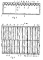
- Fig. 1 shows the side-by-side reaction vessels I, II, III with common partitions 3 and 3a without the top cover. 2, the reaction vessel I is shown with an upper cover 4. The reaction vessels II and III are separated in the exemplary embodiment by the intermediate wall 3a.
- the reaction vessels I, II and III each enclose a digester 5, an overflow space 6 and gas collecting spaces 7. Between two opposite sides 1a and 1b or 2a and 2b of the reaction vessels I or II and III, partition walls 8 and 9 extend, which form the digestion space 5 delimit upwards and the overflow space 6 downwards and which are connected in pairs to form a gable roof-shaped components 10.
- the partition walls 8 and 9, each forming a gable roof-shaped component 10, are inclined alternately by the angle ⁇ with respect to the vertical, as can be seen particularly clearly from FIG. 4.
- the downward free ends of the partitions 8 and 9 overlap each other such that a gap 11 remains between these ends. Since the free ends of the partition walls 8 extend further downward than the partition walls 9, the column 11 is covered in such a way that gas bubbles formed in the digestion chamber do not get into the gap 11, but are guided past these columns 11 during their ascending movement .
- the height of the gable roof-shaped components 10 corresponds approximately to the height of the overflow space 6, in the upper one Area overflow channels 13 are provided, which determine the water level 14 of the purified water.
- the overflow channels 13 open into collecting channels 15, as can be seen particularly clearly from FIGS. 1 and 3.
- the upper end of the reaction container is formed by a horizontal plate-shaped cover 4.
- the gas collecting spaces 7 are connected to gas outlet lines 17, which open into a collecting line 18 shown in FIG. 4. At the bottom, the gas collecting spaces 7 are limited by the water level 19 within the gable roof-shaped components.
- the height of the digester 5 is at least three times the height of the overflow space 6, the latter corresponding approximately to the height of the gable roof-shaped components 10.
- This height ratio is of particular importance and in connection with a sludge filling of the reaction container up to about half of its total height is of particular importance because, according to the invention, a reaction and sedimentation zone is to remain between the sludge filling and the overflow space, which is approximately half the height of the sludge filling .
- the gable roof-shaped components 10 are equipped with trapezoidal transverse bulkheads 20, which, however, leave the firebox of the gable roof-shaped components free, so that the gas collecting spaces 7 which are continuous in the longitudinal direction of the gable roof-shaped components are retained.
- the gable roof-shaped components 10 are supported on offset edges 21 and 22 or 23 and 24 of the reaction vessels I or II and III and at the same time also integrated into the walls 1a and 1b or 2a and 2b, so that they are stiffeners or Form tie rods for the reaction vessels.
- the gable roof-shaped components 10 consist of prefabricated concrete parts, just as the reaction vessels I, II and III in the example are made of concrete.
- tubes 25 are provided, which are beveled at their ends projecting into the digester 5 upwards in the direction of the associated partition wall.
- the tubes 25 are approximately half the height of the gable roof-shaped components 10 in the partitions 8 and 9 in the same horizontal plane, but offset from one another and extend approximately from the vertical central longitudinal plane of the gable roof-shaped components 10 to approximately the vertical separation plane between the adjacent gable roof-shaped components .
- the water-gas mixture flowing further upwards passes in the course of its flow movement into the area of the pipes 25, where the gas bubbles are deflected by the bevelled ends of the pipes 25, so that only the cleaned water passes through the pipes 25 from the digestion chamber 5 into the overflow chamber 6.
- the inflow opening of the pipes 25 is in the arrangement described in that area in which a calm upward flow of the gas-water mixture takes place without a special enrichment of gas bubbles, which in the area of contact of the gas-water mixture with the partition walls 8 and 9 occurs more often.
- the reaction vessels I or II and III are expediently at least partially let into the ground, so that the digester 5 is also at least partially in one frost-proof area.
- the wastewater to be cleaned is expediently supplied from above, since in this way it is easily possible to empty the supply lines at the end of operation.
Landscapes
- Life Sciences & Earth Sciences (AREA)
- Microbiology (AREA)
- Biodiversity & Conservation Biology (AREA)
- Hydrology & Water Resources (AREA)
- Engineering & Computer Science (AREA)
- Environmental & Geological Engineering (AREA)
- Water Supply & Treatment (AREA)
- Chemical & Material Sciences (AREA)
- Organic Chemistry (AREA)
- Purification Treatments By Anaerobic Or Anaerobic And Aerobic Bacteria Or Animals (AREA)
- Physical Water Treatments (AREA)
Priority Applications (1)
| Application Number | Priority Date | Filing Date | Title |
|---|---|---|---|
| AT83105572T ATE16272T1 (de) | 1982-06-12 | 1983-06-07 | Vorrichtung zur anaeroben abwasserreinigung. |
Applications Claiming Priority (2)
| Application Number | Priority Date | Filing Date | Title |
|---|---|---|---|
| DE3222218 | 1982-06-12 | ||
| DE3222218A DE3222218C2 (de) | 1982-06-12 | 1982-06-12 | Vorzugsweise kubischer Reaktionsbehälter zur anaeroben Abwasserreinigung |
Publications (2)
| Publication Number | Publication Date |
|---|---|
| EP0096825A1 true EP0096825A1 (fr) | 1983-12-28 |
| EP0096825B1 EP0096825B1 (fr) | 1985-10-30 |
Family
ID=6165978
Family Applications (1)
| Application Number | Title | Priority Date | Filing Date |
|---|---|---|---|
| EP83105572A Expired EP0096825B1 (fr) | 1982-06-12 | 1983-06-07 | Dispositif pour la purification anaérobie d'eau usée |
Country Status (3)
| Country | Link |
|---|---|
| EP (1) | EP0096825B1 (fr) |
| AT (1) | ATE16272T1 (fr) |
| DE (2) | DE3222218C2 (fr) |
Cited By (4)
| Publication number | Priority date | Publication date | Assignee | Title |
|---|---|---|---|---|
| EP0244029A1 (fr) * | 1986-05-01 | 1987-11-04 | Paques B.V. | Equipement pour la purification anaérobie d'eau usée |
| WO2002002467A1 (fr) * | 2000-06-30 | 2002-01-10 | Johan Verink | Dispositif de separation a trois phases pour le traitement des eaux residuaires et des boues |
| EP0808805B2 (fr) † | 1996-05-22 | 2005-12-28 | VA TECH WABAG GmbH | Procédé et réacteur pour la purification anaérobie des eaux usées dans un lit de boue |
| US20150329811A1 (en) * | 2012-02-15 | 2015-11-19 | Evergreen Gas Limited | Method of Using A Process Vessel |
Families Citing this family (2)
| Publication number | Priority date | Publication date | Assignee | Title |
|---|---|---|---|---|
| DE3723851A1 (de) * | 1987-07-18 | 1989-01-26 | Maerkl Herbert | Biogasreaktor |
| CN103663684B (zh) * | 2012-09-18 | 2015-05-13 | 中国石油化工股份有限公司 | 筒形内循环厌氧反应器的三相分离器 |
Citations (2)
| Publication number | Priority date | Publication date | Assignee | Title |
|---|---|---|---|---|
| FR1356452A (fr) * | 1963-02-15 | 1964-03-27 | Ouest Assainissement | Appareil perfectionné pour le traitement des eaux usées |
| GB2021549A (en) * | 1978-05-23 | 1979-12-05 | Centrale Suiker Mij Nv | Apparatus for the anaerobic purification of waste water |
Family Cites Families (1)
| Publication number | Priority date | Publication date | Assignee | Title |
|---|---|---|---|---|
| NL166000C (nl) * | 1976-06-24 | 1981-06-15 | Centrale Suiker Mij Nv | Inrichting voor het afscheiden van gas, slib en vloei- stof in een anaerobe zuiveringsinstallatie. |
-
1982
- 1982-06-12 DE DE3222218A patent/DE3222218C2/de not_active Expired - Lifetime
-
1983
- 1983-06-07 DE DE8383105572T patent/DE3361117D1/de not_active Expired
- 1983-06-07 EP EP83105572A patent/EP0096825B1/fr not_active Expired
- 1983-06-07 AT AT83105572T patent/ATE16272T1/de not_active IP Right Cessation
Patent Citations (2)
| Publication number | Priority date | Publication date | Assignee | Title |
|---|---|---|---|---|
| FR1356452A (fr) * | 1963-02-15 | 1964-03-27 | Ouest Assainissement | Appareil perfectionné pour le traitement des eaux usées |
| GB2021549A (en) * | 1978-05-23 | 1979-12-05 | Centrale Suiker Mij Nv | Apparatus for the anaerobic purification of waste water |
Cited By (6)
| Publication number | Priority date | Publication date | Assignee | Title |
|---|---|---|---|---|
| EP0244029A1 (fr) * | 1986-05-01 | 1987-11-04 | Paques B.V. | Equipement pour la purification anaérobie d'eau usée |
| US4758339A (en) * | 1986-05-01 | 1988-07-19 | Paques B.V. | Equipment for the anaerobic purification of waste water |
| EP0808805B2 (fr) † | 1996-05-22 | 2005-12-28 | VA TECH WABAG GmbH | Procédé et réacteur pour la purification anaérobie des eaux usées dans un lit de boue |
| WO2002002467A1 (fr) * | 2000-06-30 | 2002-01-10 | Johan Verink | Dispositif de separation a trois phases pour le traitement des eaux residuaires et des boues |
| US6929745B2 (en) | 2000-06-30 | 2005-08-16 | Johan Verink | Apparatus for three-phase separation during treatment of wastewater and sludge |
| US20150329811A1 (en) * | 2012-02-15 | 2015-11-19 | Evergreen Gas Limited | Method of Using A Process Vessel |
Also Published As
| Publication number | Publication date |
|---|---|
| DE3222218A1 (de) | 1983-12-15 |
| DE3222218C2 (de) | 1992-10-22 |
| ATE16272T1 (de) | 1985-11-15 |
| DE3361117D1 (en) | 1985-12-05 |
| EP0096825B1 (fr) | 1985-10-30 |
Similar Documents
| Publication | Publication Date | Title |
|---|---|---|
| DE69603173T2 (de) | Ablagerungsvorrichtung für eine flüssigkeit, gas und partikelförmiges material enthaltendes fluidum, sowie eine mit einer solchen vorrichtung ausgerüsteten reinigungsanlage und reinigungsverfahren | |
| EP0808805B2 (fr) | Procédé et réacteur pour la purification anaérobie des eaux usées dans un lit de boue | |
| DE2920978C2 (de) | Vorrichtung zur anaeroben Abwasserreinigung | |
| DE3206416A1 (de) | Mehrphasenabscheider | |
| DE2707872A1 (de) | Absetztank | |
| EP0096825B1 (fr) | Dispositif pour la purification anaérobie d'eau usée | |
| DE3228222A1 (de) | Abscheider, insbesondere zum abscheiden von oel und sand aus abwasser | |
| DE3339317C2 (fr) | ||
| EP0564935A1 (fr) | Station d'épuration d'eaux usées | |
| DE2837554C2 (de) | Leichtflüssigkeitsabscheider | |
| DE3126078C2 (de) | Vorrichtung zur Abwasserreinigung | |
| AT517984B1 (de) | Trennbehälter | |
| DE2728585C3 (de) | Vorrichtung zur anaeroben Reinigung von Abwasser | |
| EP0308949A2 (fr) | Séparateur de liquides légers | |
| EP0162121B1 (fr) | Clarificateur pour la purification biologique d'eaux usées | |
| DE19800664C2 (de) | Verfahren zur biologischen Abwasserreinigung und Anlage zur Durchführung des Verfahrens | |
| DE2230725B2 (de) | Vorrichtung zur biologischen Reinigung organische Abfallfeststoffe, insbesondere Fäkalien enthaltender Flüssigkeiten | |
| DE3326326C2 (fr) | ||
| DE2627598A1 (de) | Einrichtung zum abscheiden und rueckhalten von nicht geloesten kohlenwasserstoffen aus wasser | |
| DE2136397B2 (de) | Phasenscheider für Flüssig-Flfissig-Extraktoren | |
| DE2703379C2 (de) | Belebtschlammanlage zur Abwasserreinigung | |
| DE2302146C3 (de) | Belebungsbecken für Kläranlagen | |
| DE3206302C2 (de) | Belebtschlammanlage zur biologischen Abwasserreinigung | |
| DE19842884C2 (de) | Verfahren zur biologischen und biologisch-chemischen Aufbereitung von Abwasser mit integriertem Schlammabscheider | |
| DE538759C (de) | In einem Behaelter zur kontinuierlichen Trennung von Fluessigkeiten verschiedenen spezifischen Gewichtes unterzubringende Vorrichtung zur Stroemungsberuhigung |
Legal Events
| Date | Code | Title | Description |
|---|---|---|---|
| PUAI | Public reference made under article 153(3) epc to a published international application that has entered the european phase |
Free format text: ORIGINAL CODE: 0009012 |
|
| AK | Designated contracting states |
Designated state(s): AT DE FR GB IT |
|
| 17P | Request for examination filed |
Effective date: 19840622 |
|
| ITF | It: translation for a ep patent filed | ||
| GRAA | (expected) grant |
Free format text: ORIGINAL CODE: 0009210 |
|
| AK | Designated contracting states |
Designated state(s): AT DE FR GB IT |
|
| REF | Corresponds to: |
Ref document number: 16272 Country of ref document: AT Date of ref document: 19851115 Kind code of ref document: T |
|
| REF | Corresponds to: |
Ref document number: 3361117 Country of ref document: DE Date of ref document: 19851205 |
|
| ET | Fr: translation filed | ||
| PLBI | Opposition filed |
Free format text: ORIGINAL CODE: 0009260 |
|
| 26 | Opposition filed |
Opponent name: GIST-BROCADES N.V. Effective date: 19860729 |
|
| RAP2 | Party data changed (patent owner data changed or rights of a patent transferred) |
Owner name: HANNOVER ZUCKER AKTIENGESELLSCHAFT LEHRTE |
|
| ITTA | It: last paid annual fee | ||
| RAP2 | Party data changed (patent owner data changed or rights of a patent transferred) |
Owner name: ZUCKERVERBUND NORD AKTIENGESELLSCHAFT |
|
| PLBN | Opposition rejected |
Free format text: ORIGINAL CODE: 0009273 |
|
| STAA | Information on the status of an ep patent application or granted ep patent |
Free format text: STATUS: OPPOSITION REJECTED |
|
| 27O | Opposition rejected |
Effective date: 19920610 |
|
| PGFP | Annual fee paid to national office [announced via postgrant information from national office to epo] |
Ref country code: FR Payment date: 19970430 Year of fee payment: 15 |
|
| PGFP | Annual fee paid to national office [announced via postgrant information from national office to epo] |
Ref country code: GB Payment date: 19970527 Year of fee payment: 15 |
|
| PGFP | Annual fee paid to national office [announced via postgrant information from national office to epo] |
Ref country code: AT Payment date: 19970630 Year of fee payment: 15 |
|
| PG25 | Lapsed in a contracting state [announced via postgrant information from national office to epo] |
Ref country code: GB Free format text: LAPSE BECAUSE OF NON-PAYMENT OF DUE FEES Effective date: 19980607 Ref country code: AT Free format text: LAPSE BECAUSE OF NON-PAYMENT OF DUE FEES Effective date: 19980607 |
|
| GBPC | Gb: european patent ceased through non-payment of renewal fee |
Effective date: 19980607 |
|
| PG25 | Lapsed in a contracting state [announced via postgrant information from national office to epo] |
Ref country code: FR Free format text: LAPSE BECAUSE OF NON-PAYMENT OF DUE FEES Effective date: 19990226 |
|
| REG | Reference to a national code |
Ref country code: FR Ref legal event code: ST |
|
| PGFP | Annual fee paid to national office [announced via postgrant information from national office to epo] |
Ref country code: DE Payment date: 20000722 Year of fee payment: 18 |
|
| PG25 | Lapsed in a contracting state [announced via postgrant information from national office to epo] |
Ref country code: DE Free format text: LAPSE BECAUSE OF NON-PAYMENT OF DUE FEES Effective date: 20020403 |
|
| APAH | Appeal reference modified |
Free format text: ORIGINAL CODE: EPIDOSCREFNO |