EP0097009A1 - Drahtpunktdrucker - Google Patents
Drahtpunktdrucker Download PDFInfo
- Publication number
- EP0097009A1 EP0097009A1 EP83303218A EP83303218A EP0097009A1 EP 0097009 A1 EP0097009 A1 EP 0097009A1 EP 83303218 A EP83303218 A EP 83303218A EP 83303218 A EP83303218 A EP 83303218A EP 0097009 A1 EP0097009 A1 EP 0097009A1
- Authority
- EP
- European Patent Office
- Prior art keywords
- ink
- printer
- printing
- applicator device
- heating means
- Prior art date
- Legal status (The legal status is an assumption and is not a legal conclusion. Google has not performed a legal analysis and makes no representation as to the accuracy of the status listed.)
- Granted
Links
- 238000010438 heat treatment Methods 0.000 claims abstract description 17
- 239000007787 solid Substances 0.000 claims description 17
- 239000004020 conductor Substances 0.000 claims description 3
- 239000000976 ink Substances 0.000 description 282
- 239000003086 colorant Substances 0.000 description 13
- 238000010276 construction Methods 0.000 description 8
- 239000002184 metal Substances 0.000 description 6
- 230000000694 effects Effects 0.000 description 5
- 239000000975 dye Substances 0.000 description 4
- 238000002474 experimental method Methods 0.000 description 3
- 239000004033 plastic Substances 0.000 description 3
- 229920003023 plastic Polymers 0.000 description 3
- 239000002904 solvent Substances 0.000 description 3
- XLYOFNOQVPJJNP-UHFFFAOYSA-N water Substances O XLYOFNOQVPJJNP-UHFFFAOYSA-N 0.000 description 3
- PEDCQBHIVMGVHV-UHFFFAOYSA-N Glycerine Chemical compound OCC(O)CO PEDCQBHIVMGVHV-UHFFFAOYSA-N 0.000 description 2
- 230000008901 benefit Effects 0.000 description 2
- 229910052799 carbon Inorganic materials 0.000 description 2
- 230000008859 change Effects 0.000 description 2
- 238000007599 discharging Methods 0.000 description 2
- 230000008020 evaporation Effects 0.000 description 2
- 238000001704 evaporation Methods 0.000 description 2
- 239000007788 liquid Substances 0.000 description 2
- 239000000463 material Substances 0.000 description 2
- 238000000034 method Methods 0.000 description 2
- 230000004048 modification Effects 0.000 description 2
- 238000012986 modification Methods 0.000 description 2
- 230000008569 process Effects 0.000 description 2
- 230000004044 response Effects 0.000 description 2
- 229910001220 stainless steel Inorganic materials 0.000 description 2
- 239000010935 stainless steel Substances 0.000 description 2
- 239000000126 substance Substances 0.000 description 2
- OKTJSMMVPCPJKN-UHFFFAOYSA-N Carbon Chemical compound [C] OKTJSMMVPCPJKN-UHFFFAOYSA-N 0.000 description 1
- 239000002202 Polyethylene glycol Substances 0.000 description 1
- 230000002411 adverse Effects 0.000 description 1
- 238000003491 array Methods 0.000 description 1
- 230000015572 biosynthetic process Effects 0.000 description 1
- 230000008878 coupling Effects 0.000 description 1
- 238000010168 coupling process Methods 0.000 description 1
- 238000005859 coupling reaction Methods 0.000 description 1
- 230000005574 cross-species transmission Effects 0.000 description 1
- 239000006185 dispersion Substances 0.000 description 1
- 230000009969 flowable effect Effects 0.000 description 1
- 235000011187 glycerol Nutrition 0.000 description 1
- 230000006872 improvement Effects 0.000 description 1
- 230000007246 mechanism Effects 0.000 description 1
- 239000000049 pigment Substances 0.000 description 1
- 229920001223 polyethylene glycol Polymers 0.000 description 1
- 239000011148 porous material Substances 0.000 description 1
- 230000002265 prevention Effects 0.000 description 1
- 230000009467 reduction Effects 0.000 description 1
- 230000000717 retained effect Effects 0.000 description 1
- 229920002379 silicone rubber Polymers 0.000 description 1
- 239000004945 silicone rubber Substances 0.000 description 1
- 229940099259 vaseline Drugs 0.000 description 1
Images



Classifications
-
- B—PERFORMING OPERATIONS; TRANSPORTING
- B41—PRINTING; LINING MACHINES; TYPEWRITERS; STAMPS
- B41J—TYPEWRITERS; SELECTIVE PRINTING MECHANISMS, i.e. MECHANISMS PRINTING OTHERWISE THAN FROM A FORME; CORRECTION OF TYPOGRAPHICAL ERRORS
- B41J2/00—Typewriters or selective printing mechanisms characterised by the printing or marking process for which they are designed
- B41J2/22—Typewriters or selective printing mechanisms characterised by the printing or marking process for which they are designed characterised by selective application of impact or pressure on a printing material or impression-transfer material
- B41J2/23—Typewriters or selective printing mechanisms characterised by the printing or marking process for which they are designed characterised by selective application of impact or pressure on a printing material or impression-transfer material using print wires
- B41J2/305—Ink supply apparatus
-
- B—PERFORMING OPERATIONS; TRANSPORTING
- B41—PRINTING; LINING MACHINES; TYPEWRITERS; STAMPS
- B41J—TYPEWRITERS; SELECTIVE PRINTING MECHANISMS, i.e. MECHANISMS PRINTING OTHERWISE THAN FROM A FORME; CORRECTION OF TYPOGRAPHICAL ERRORS
- B41J2/00—Typewriters or selective printing mechanisms characterised by the printing or marking process for which they are designed
- B41J2/22—Typewriters or selective printing mechanisms characterised by the printing or marking process for which they are designed characterised by selective application of impact or pressure on a printing material or impression-transfer material
- B41J2/23—Typewriters or selective printing mechanisms characterised by the printing or marking process for which they are designed characterised by selective application of impact or pressure on a printing material or impression-transfer material using print wires
- B41J2/235—Print head assemblies
- B41J2/25—Print wires
- B41J2/255—Arrangement of the print ends of the wires
Definitions
- the present invention relates to a wire dot printer.
- the object of the present invention is to improve such a wire dot printer by providing means of avoiding spattering of ink when the wire end faces strike against a sheet of print paper at the time of printing, and by reducing changes in printing density due to temperature changes.
- Another object of the present invention is to provide a wire dot printer in which the ink remains unchanged in its characteristics after it has been left unused, and which is capable of stable high-quality printing for an extended period of time.
- a still further object of the present invention is to provide a wire dot printer which allows easy hue adjustments in a multicolour printing operation.
- a wire dot printer comprising a plurality of printing wires, and at least one ink applicator device for applying ink to end faces of said printing wires, characterised by ink heating means which are arranged in operation to heat the said ink.
- the ink heating means may be disposed adjacent to the said end faces or may be disposed in an ink supply passage for supplying ink to the'or an ink applicator device.
- Pump means may be provided for supplying ink to the ink applicator device or devices.
- ink applicator devices there may be a plurality of ink applicator devices the printing wires being divided into groups of wires each group of which is mounted in a respective ink applicator device.
- the ink heating means may comprise a plurality of independent heaters each of which is associated with a respective ink applicator device.
- Each ink applicator device may comprise a wire guide member of electrically conductive material.
- the ink heating means may be arranged in operation to maintain the temperature of the ink at a predetermined value or within a predetermined range.
- Means may be provided for urging the ink to flow to the said end faces under capillary attraction.
- the last-mentioned means may be thermally conductive and may be secured to the ink heating means.
- the last4mentioned means may constitute or form part of the ink heating means.
- the last-mentioned means may, moreover, extend into an ink tank.
- the printer may be used with ink which is solid or semi-solid at normal temperature.
- Figure 1 shows in perspective an exploded perspective view of a first embodiment of a wire dot printer according to the present invention.
- the wire dot printer shown in Figure 1 includes a dot print head (hereinafter referred to as a "head") 1 which is fixed to a carriage 2 by bolts 5, 6.
- the movement of the carriage. 2 is guided by a pair of carriage guide shafts 3, 4 which extend between a pair of opposite printer frame members (not shown).
- the carriage guide shafts 3, 4 extend parallel to a platen 19 such that the carriage 2 can be reciprocated parallel to the platen 19.
- An ink supply and discharge guide 7 is mounted in a nose la of the head 1 for guiding printing wires 30 ( Figure 2(a)).
- the ink supply and discharge guide 7 cooperate with a wire end guide 8 and an ink application plate 9 in defining an ink passage for controlling the application of ink to end faces 30a ( Figure 2(c)) of the printing wires 30.
- An ink heater unit 10, which is disposed adjacent to the end faces 30a, is secured to the nose la and includes a heater element connected to a pair of lead wires loa, lOb coupled to a power supply (not shown).
- a tube connector 11 has one end connected to pipes 7a, 7b of the ink supply and discharge guide 7 and the other end coupled to elastic tubes 12, e.g. of silicone rubber, leading to an ink supply and discharge pump 13.
- the ink supply and discharge pump 13 has a pump gear 18 that is rotated by a motor 14 through a train of gears 15, 16, 17 for supplying ink to the ink supply and discharge guide 7 and discharging ink from the ink supply and discharge guide 7.
- the ink supply and discharge pump 13 is of a known tube pump construction employing an elastic tube therein, and hence will not be described in detail.
- An ink tank 22 is fitted in a tank guide 21.
- the latter has on its bottom a pair of upstanding hollow metal pipes 20 which engage the ink tank 22 and serve as a coupling for supplying and discharging ink therethrough.
- ink is supplied from the ink tank 22 through one of the hollow pipes 20, one of elastic tubes 12 interconnecting the hollow pipes 20 and the ink supply and discharge pump 13, the ink supply and discharge pump 13, one of the elastic tubes 12, the tube connector 11, and the pipes 7a of the ink supply and discharge guide 7. Any excess ink in the head 1 is discharged from the ink supply and discharge guide 7 through the pipe 7b, the tube connector 11, the other elastic tube 12, the ink supply and discharge pump 13, the other elastic tube 12, and the other hollow pipe 20 back to the ink tank 22.
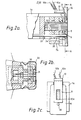
- FIG. 2(a), 2(b) and 2(c) An ink passage and ink applicator device for use in the head of the ink dot printer of Figure 1 is illustrated in Figures 2(a), 2(b) and 2(c).
- a multiplicity of the printing wires 30 are guided by wire guides 34, 35.
- the ink passage and ink applicator device is constituted jointly by the ink supply and discharge guide 7, the wire end guide 8, and the ink application plate 9, which also serve to guide the wires 30.
- the ink heater unit 10 is secured to a thermally conductive metal plate 31 which has good thermal conductivity and which serves to heat the ink as supplied to the ink applicator device.
- the thermally conductive plate 31 is shaped to surround the wires 30 and has a lower portion embedded in the wire end guide 8.
- the ink application plate 9 is pressed against the wire end guide 8 by a guide holder 32.
- Wire guides 34, 35 are positioned in place by a positioning rod 33 extending therethrough.
- ink applicator device The operation of the ink applicator device is described below. Since the manner in which ink is applied to the wire end faces is described in detail in the European Patent Application No. 81302692.9, the ink applicator device will be described here mainly with reference to the ink heater.
- the ink supplied by the ink supply and discharge pump 13 is fed into the head 1 through the supply pipe 7a of the ink supply and discharge guide 7.
- The-ink then flows across the wires 30 through a space (ink passage) 36 which is defined between the ink supply and discharge guide 7 and the wire end guide 8.
- the ink is forced from the ink passage 36 under capillary attraction into gaps between the edges of holes in the wire guides and the wires 30 and also into clearances between the wires 30, and then is applied to the wire end faces. Any excess ink is collected via the discharge pipe 7b.
- the thermally conductive plate 31 surrounds the wires 30 for heating the ink around the plate 31 up to a predetermined temperature.
- the ink heater unit 10 used is of a self-control type capable of maintaining the ink temperature at a constant value
- the ink heater unit 10 is connected directly to a power supply. If the ink heater unit 10 merely has a heater element, it should be combined with a thermally sensitive device for temperature control.
- Figure 7 illustrates the relationship between the viscosity and the temperature of an ink which may be used in a wire dot printer according to the present invention.
- the ink viscosity is of the order of a few hundred cp (centipoise) at normal temperature, and is preferably in the range of 5 to 50 cp for printing when heated to 60 to 80°C.
- ink viscosity increases and the ink flowability is reduced as the temperature is lowered. At lower temperatures, therefore, the ink supplied tends to be insufficient, resulting in a lower printing density. For this reason, inks of a low viscosity such as 10 cp or below at normal temperature have conventionally been widely used. With low-viscosity inks, however, the amount of the dye and solvent contained in the ink cannot be increased due to the required degree of low viscosity. To render the ink less viscous, a large proportion of water or other substance having a high tendency to evaporate is added to the ink.
- ink is supplied to the head 1 by the ink supply and discharge pump 13. Substantially at the same time, the ink heater unit 10 is heated to increase the temperature of the ink around the thermally conductive plate 31. When the ink temperature reaches a prescribed level, the carriage 2 is actuated to start printing. During the printing process, the ink heater unit 10 is controlled to keep constant the temperature of the ink at the distal ends of the wires 30.
- the ink temperature is set at a value which is not adversely affected by an increase in the temperature of the head and/or by an increase in the ambient temperature during the printing operation.
- the ink is such that its properties will be at their optimum values for the printing quality when the ink is heated.
- the ink viscosity is related to the dispersion of the ink during the printing operation; as the ink viscosity increases, the ink is less dispersed or scattered around. If the ink viscosity is too high, however, the printing density is reduced so that there is a failure to effect clear printing, as described above.
- the inventors carried out experiments and found that substantially no ink dispersal occurs and sharp printing is possible at an ink viscosity ranging from 5 to 50 cp.
- the high-viscosity ink which is of a few hundred cp at normal temperature is heated by the ink heater during the printing process to keep the ink viscosity in the range of from 5 to 50 cp. This maintains the ink viscosity constant during the printing operation, thereby stalilizing the printing density, reducing ink scattering and improving the printing quality.
- the high-viscosity ink used contains no water or other substance which can easily evaporate, but a solvent such as polyethyleneglycol, glycerine or the like, and therefore is highly resistant to evaporation. This high-viscosity ink assures stable printing quality even after the ink has been left unused for a long period of time. Since it is not necessary to reduce the ink viscosity, the amount of dye and a solvent therefor in the ink can be increased for a higher printing density.
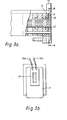
- FIG. 3 shows an ink heater which may be employed in another embodiment of a wire dot printer according to the present invention.
- a heater 40 is directly embedded in a wire end guide 41 and protected by a heater protection member 42.
- the heater 40 is disposed adjacent to the ends of the wires 30 where the ink is applied. This arrangement allows a reduction of the time required to heat the ink and simplifies the overall ink applicator device.
- an electrically conductive material may be deposited by way of evaporation on the wire end guide 41 and other wire guides, or by constructing these wire guides of electrically conductive plastics material in which carbon and the like are added to plastics, so that these wire guides per se may be connected to an electrical power source so that the wire guides themselves will produce heat.
- the ink heater 40 is secured to the wire end guide 41.
- the ink heater 40 may be attached to any other structure for heating the distal ends of the wires 30.
- the ink heater 40 may be located anywhere in the ink supply system between the ink tank and the ink applicator device. However, it is most effective to locate the ink heater 40 in the vicinity of the end faces of the wires 30 to which the ink is applied.
- the present invention assists considerably in the prevention of ink dispersal, the improvement of printing quality, and the increase in printing stability for a long time, tasks which it has been most difficult for conventional ink-supplied dot printers to perform.
- a heater construction with an ink supply function which employs high-viscosity ink and which may be employed in still another embodiment of a wire dot printer according to the present invention will be described with reference to Figures 4(a), 4(b) and 4(c).
- a wire end guide 50 and a thermally conductive plate 51 to which a heater 52 is secured jointly constitute a heater unit.
- An ink supply member 53 is disposed in intimate contact with the heater unit and comprises a mass of fibres, a body of porous plastics, a mesh of stainless steel or other metal, or any other construction having minute interstices, which provide capillary attraction.
- the thermally conductive plate 51 and the ink supply member 53 are fixed in position by a fixture plate 54 having a lower portion extending into an ink tank 55, in which the thermally conductive plate 51 and the ink supply member 53 are minimised in high-viscosity ink 57 whose viscosity is of a few hundred cp.
- the fixture plate 54 is secured to the nose la so that the fixture plate 54 is joined firmly to the head 1.
- An ink applicator device is composed of the wire end guide 50, the ink supply member 53 and the ink application plate 9, the ink tank 55 being located adjacent to the ink applicator device.
- the ink supply member 53 may be of any construction capable of providing capillary attraction, and thus may be made of any of the materials listed above.
- the ink 57 which is led into the ink applicator device is applied to the wire end faces for the printing operation, as with the foregoing embodiment.
- the heater unit thus heats the high-viscosity ink until the latter has a lowered viscosity and increased flowability, which allows the ink to be supplied through the ink supply member 53 at an accelerated rate under the capillary attraction thereof.
- the ink viscosity should be selected so as to achieve the highest printing quality.
- the ink supply member 53 extends between the ink 57 in the ink tank 55 and the ink applicator device.
- the ink 57 can be brought into the condition best suited for the printing operation from the instant the ink 57 is heated, and can be put to use for the printing in such best condition.
- the flowability of the ink 57 can be controlled by varying the temperature of the heater unit to change the amount of ink staying at the ink application end, for therebycontrolling the printing density.
- the ink-supplied wire dot printer includes an ink applicator device, an ink tank disposed in the vicinity of the ink applicator device, the ink applicator device having an ink supply member providing capillary attraction for supplying ink from the ink tank to the wire end faces, and a heater unit for heating the ink supply member.
- the ink supply member 53 may serve as a thermally conductive plate in the form of a sandwiched construction composed of a mesh of stainless steel or other metal or a metal plate having minute pores.
- the ink supply member 53 may comprise a mesh of metal having a high electric resistance such that it will be heated when an electric current is passed therethrough.
- the high-viscosity ink has a few hundred cp in the foregoing embodiment. Nevertheless, the ink, when heated by the heater unit is 60 -80°C, will have an optimum viscosity for printing, such as 5 - 50 cp.
- FIG. 5 shows an ink supply member and an ink applicator for use with such a semi-solid or solid ink.
- a mass of semi-solid or solid ink (hereinafter referred to as "solid ink") 60 is contained in an ink casing 62.
- a heater unit member 61 is placed in the mass of solid ink 60 in coiled formation and is connected to an ink applicator device. The ink is supplied to the ink applicator device in the same manner as described above.
- the ink When the solid ink is employed, therefore, the ink will not be scattered around and a high printing quality can be maintained.
- the solid ink is quite easy to handle since it does not spill over or leak through the ink casing as does the liquid ink.
- Figures 6(a) and 6(b) are illustrative of a print head forming part of a wire dot printer according to the present invention which is adapted to use inks of different colours.
- the printing head is adapted to employ inks of three primary colours that is, yellow, magenta and cyan, which are indicated by Y, M and C, respectively.
- Inks Y, M, C are fed through ink supply ports 81Y, 81M, 81C and ink passages 82Y, 82M, 82C to ink collection ports 83 Y , 83M, 83C, respectively.
- the ink passages 82Y, 82M, 82C are defined between an ink supply and discharge guide 71 and wire end guides 73.
- Arrays or groups of wires 86Y, 86M, 86C are mounted in their respective ink applicator devices. and associated with ink application guides 74 which assure stable application of the inks to the wires.
- the manner in which the inks are applied to the wires is described in detail in the above- mentioned European Patent Application No. 81302692.9 and therefore will not be described here.
- the ink applicator devices are separated from each other by walls 71a, 71b, 71c, 71d which extend in a vertical direction as seen in Figure 6(b) for preventing the inks in the ink applicator devices from being mixed together.
- the inks Y, M and C are respectively supplied from independent ink tanks (not shown), through their respective supply tubes (not shown) to the ink supply and discharge guide 71 at the distal end of the print head, and any excess inks are returned to and collected by the said ink tanks.
- Heaters 70a, 70b, 70c and thermally conductive plates 72a, 72b, 72c combined therewith are independently provided respectively for the three coloured inks.
- the thermally conductive plates 72a, 72b, 72c are embedded in respective wire end guides 73.
- the wire dot printer of the invention is capable of high-quality printing and can be fabricated at a lower cost if no pump is employed.
- the hues of the printed characters and symbols can be adjusted. More specifically, the inks of different colours respectively in the spaces between the wire end guides 73 and the ink supply and discharge guide 71 can be controlled in their temperature independently by the heaters 70a, 70b, 70c. The variable heater temperatures can then control the flowability of the inks to thereby change the amounts of inks retained in the ink applicator devices.
- the colour red can be provided by adding together the colours Y and M
- the colour blue can be provided by adding together the colours M and C
- the colour green can be provided by adding together the colours C and Y
- the colour black can be provided by adding together the colours Y, M and C if the amounts of the inks of the respective three colours applied to the respective wires are equal.
- the amounts of the inks are varied by controlling the heater temperatures, other colours can be printed. For example, where inks Y and M are added in different quantities, printing can be effected in a colour tinted with the colour of the ink supplied in the larger amount.
- the hues of the printed characters or symbols can be corrected through control of the heater temperatures without modifying the ink applicator devices. Since the coloured inks contain different dyes, they cannot be the same in properties. It is possible with the present invention to adjust the 'heater temperatures for compensating for the differences in the properties of the inks used even though equivalent ink applicator devices for the various inks are employed.
- a wire dot printer in accordance with the present invention can thus effect high-quality coloured printing and make simple hue adjustments.
- the colour print head has been described as using inks of three primary colours, the present invention is also applicable to a colour printing head for use with four kinds of inks of three primary colours and black.
- the heaters 70a, 70b, 70c may be of an integral construction provided that the ink application structures and the ink properties are perfectly stable. This alternative arrangement is capable of uniformly controlling the printing density for each colour as is the previous ink application construction using ink of a single colour.
Landscapes
- Ink Jet (AREA)
- Impact Printers (AREA)
Applications Claiming Priority (2)
| Application Number | Priority Date | Filing Date | Title |
|---|---|---|---|
| JP57099548A JPS58215370A (ja) | 1982-06-10 | 1982-06-10 | インク式ワイヤドツトプリンタ |
| JP99548/82 | 1982-06-10 |
Publications (2)
| Publication Number | Publication Date |
|---|---|
| EP0097009A1 true EP0097009A1 (de) | 1983-12-28 |
| EP0097009B1 EP0097009B1 (de) | 1986-02-26 |
Family
ID=14250230
Family Applications (1)
| Application Number | Title | Priority Date | Filing Date |
|---|---|---|---|
| EP83303218A Expired EP0097009B1 (de) | 1982-06-10 | 1983-06-03 | Drahtpunktdrucker |
Country Status (4)
| Country | Link |
|---|---|
| US (1) | US4553865A (de) |
| EP (1) | EP0097009B1 (de) |
| JP (1) | JPS58215370A (de) |
| DE (1) | DE3362274D1 (de) |
Cited By (2)
| Publication number | Priority date | Publication date | Assignee | Title |
|---|---|---|---|---|
| EP0148006A3 (en) * | 1983-12-23 | 1985-08-07 | Epson Corporation | Ink for use in an ink wire dot printer |
| GB2192367A (en) * | 1986-07-08 | 1988-01-13 | Seikosha Kk | Method of making a wire printer |
Families Citing this family (12)
| Publication number | Priority date | Publication date | Assignee | Title |
|---|---|---|---|---|
| US5328279A (en) * | 1984-05-22 | 1994-07-12 | Seiko Epson Corporation | Dot matrix printer head |
| US6145974A (en) * | 1983-10-13 | 2000-11-14 | Seiko Epson Corporation | Ink-supplied printer head and ink container |
| US6247803B1 (en) | 1983-10-13 | 2001-06-19 | Seiko Epson Corporation | Ink jet recording apparatus and method for replenishing ink in the tank cartridge |
| US6276785B1 (en) | 1983-10-13 | 2001-08-21 | Seiko Epson Corporation | Ink-supplied printer head and ink container |
| US6474798B1 (en) | 1984-10-11 | 2002-11-05 | Seiko Epson Corporation | Ink supplied printer head and ink container |
| US4696589A (en) * | 1984-10-26 | 1987-09-29 | Tokyo Electric Co., Ltd. | Ink-dot printer |
| US4808227A (en) * | 1986-07-30 | 1989-02-28 | Canon Kabushiki Kaisha | Semi-solid ink |
| US6238042B1 (en) | 1994-09-16 | 2001-05-29 | Seiko Epson Corporation | Ink cartridge for ink jet printer and method of charging ink into said cartridge |
| JP3245092B2 (ja) * | 1996-09-11 | 2002-01-07 | キヤノン株式会社 | 液体注入方法 |
| WO2004026385A1 (ja) * | 2002-09-20 | 2004-04-01 | I.S.T Corporation | 医療用ガイドワイヤー及びその製造方法 |
| JP2008086575A (ja) * | 2006-10-02 | 2008-04-17 | Ist Corp | 着色医療用具の製造方法 |
| JP6171313B2 (ja) * | 2011-12-08 | 2017-08-02 | セイコーエプソン株式会社 | 液体噴射装置 |
Citations (2)
| Publication number | Priority date | Publication date | Assignee | Title |
|---|---|---|---|---|
| US4279519A (en) * | 1979-06-01 | 1981-07-21 | Centronics Data Computer Corp. | Dot matrix printing device employing novel image transfer technique for printing on single ply or multiple ply print receiving media |
| EP0042293A2 (de) * | 1980-06-17 | 1981-12-23 | Seiko Epson Corporation | Drahtpunktdrucker |
Family Cites Families (14)
| Publication number | Priority date | Publication date | Assignee | Title |
|---|---|---|---|---|
| US3858703A (en) * | 1973-01-05 | 1975-01-07 | Centronics Data Computer | Bidirectional dual head printer |
| JPS555429B2 (de) * | 1973-09-26 | 1980-02-06 | ||
| US3985216A (en) * | 1975-04-14 | 1976-10-12 | Centronics Data Computer Corporation | Thermal print head assembly |
| US3999190A (en) * | 1975-10-22 | 1976-12-21 | Burroughs Corporation | Temperature control system for ink jet printer |
| US4119836A (en) * | 1975-11-26 | 1978-10-10 | Kakogawa Plastics Kabushiki Kaisha | Heat-controlled doctor knife |
| US4106030A (en) * | 1977-02-14 | 1978-08-08 | Recognition Equipment Incorporated | Ink jet printer ink heater |
| US4199675A (en) * | 1977-06-23 | 1980-04-22 | Nordson Corporation | Electric fluid heater |
| JPS54123950A (en) * | 1978-03-17 | 1979-09-26 | Matsushita Electric Ind Co Ltd | Ink jet recorder |
| US4194846A (en) * | 1978-04-28 | 1980-03-25 | Centronics Data Computer Corp. | Dot matrix printing device employing a novel image transfer technique to print on single or multiple ply print receiving materials |
| US4275290A (en) * | 1978-05-08 | 1981-06-23 | Northern Telecom Limited | Thermally activated liquid ink printing |
| US4296421A (en) * | 1978-10-26 | 1981-10-20 | Canon Kabushiki Kaisha | Ink jet recording device using thermal propulsion and mechanical pressure changes |
| DE2945658A1 (de) * | 1978-11-14 | 1980-05-29 | Canon Kk | Fluessigkeitsstrahl-aufzeichnungsverfahren |
| DE2903339C3 (de) * | 1979-01-29 | 1987-06-19 | Siemens AG, 1000 Berlin und 8000 München | Schaltungsanordnung zur temperaturabhängigen Spannungsregelung für piezoelektrische Schreibdüsen in Tintenmosaikschreibeinrichtungen |
| JPS5670962A (en) * | 1979-11-16 | 1981-06-13 | Ricoh Co Ltd | Controlling method for ink density |
-
1982
- 1982-06-10 JP JP57099548A patent/JPS58215370A/ja active Pending
-
1983
- 1983-06-03 DE DE8383303218T patent/DE3362274D1/de not_active Expired
- 1983-06-03 EP EP83303218A patent/EP0097009B1/de not_active Expired
- 1983-06-09 US US06/502,857 patent/US4553865A/en not_active Expired - Lifetime
Patent Citations (2)
| Publication number | Priority date | Publication date | Assignee | Title |
|---|---|---|---|---|
| US4279519A (en) * | 1979-06-01 | 1981-07-21 | Centronics Data Computer Corp. | Dot matrix printing device employing novel image transfer technique for printing on single ply or multiple ply print receiving media |
| EP0042293A2 (de) * | 1980-06-17 | 1981-12-23 | Seiko Epson Corporation | Drahtpunktdrucker |
Cited By (4)
| Publication number | Priority date | Publication date | Assignee | Title |
|---|---|---|---|---|
| EP0148006A3 (en) * | 1983-12-23 | 1985-08-07 | Epson Corporation | Ink for use in an ink wire dot printer |
| US4610554A (en) * | 1983-12-23 | 1986-09-09 | Seiko Epson Corporation | Ink composition and wire dot printer including same |
| GB2192367A (en) * | 1986-07-08 | 1988-01-13 | Seikosha Kk | Method of making a wire printer |
| GB2192367B (en) * | 1986-07-08 | 1990-09-19 | Seikosha Kk | Method of making a wire printer |
Also Published As
| Publication number | Publication date |
|---|---|
| EP0097009B1 (de) | 1986-02-26 |
| US4553865A (en) | 1985-11-19 |
| JPS58215370A (ja) | 1983-12-14 |
| DE3362274D1 (en) | 1986-04-03 |
Similar Documents
| Publication | Publication Date | Title |
|---|---|---|
| EP0097009B1 (de) | Drahtpunktdrucker | |
| EP0568247B1 (de) | Tintenkanalgeometrie für Hochtemperaturbetrieb von Tintenstrahlköpfen | |
| US4571599A (en) | Ink cartridge for an ink jet printer | |
| EP0031453B1 (de) | Band für thermischen Transferdruck und Druckverfahren, wobei diese Bänder verwendet werden | |
| EP0569156B1 (de) | Optimierung der Druckqualität und Zuverlässigkeit bei einem CYMK-Drucksystem | |
| DE69626436T2 (de) | Flüssigkeitsausstosskopf, Flüssigkeitsausstossvorrichtung und Flüssigkeitsausstossverfahren | |
| US5745140A (en) | Color ink-jet printer with pigment black and dye-based color inks | |
| DE69411091T2 (de) | Flüssigkeitsstrahlaufzeichnungskopf und damit versehene Flüssigkeitsstrahldruckvorrichtung | |
| JP2000141664A (ja) | インクジェットプリンタの作動方法 | |
| EP0953614B1 (de) | Sortiment von reaktiven Tinten für den Tintenstrahldruck | |
| DE69628234T2 (de) | Tintenstrahlkopf, Tintenstrahlvorrichtung und Tintenstrahlaufzeichnungsverfahren | |
| JP2003118124A (ja) | 熱除去能力が強化された熱インクジェットプリンタおよびその製造方法 | |
| BRPI1000119A2 (pt) | configuração de elemento de aquecimento para um aquecedor de reservatório | |
| US4929964A (en) | Method for preparing liquid jet recording head, liquid jet recording head prepared by said method and liquid jet recording device having said liquid jet recording head mounted thereon | |
| DE69129473T2 (de) | Aufzeichnungskopf mit Flüssigkeitsausstoss | |
| DE69815937T2 (de) | Ein einen getrennt einsetzbaren Filterträger verwendetes Tintenzuführsystem | |
| DE60030604T2 (de) | Tintenstrahldrucker | |
| US6476842B1 (en) | Transfer printing | |
| US6536886B1 (en) | Reservoir integration for multi-part inkjet printing system, and method | |
| WO1988008371A1 (en) | Pulsed constant current source for continuous tone resistive ribbon printers | |
| JP2836167B2 (ja) | インクジェットプリントヘッド | |
| US20040055484A1 (en) | Multi-viscosity printer ink | |
| Adams | Phase-change ink-jet technology | |
| JPH0872232A (ja) | インクジェット記録装置 | |
| JPH0542679A (ja) | ホツトメルト式インクジエツトプリンタのインク供給装置 |
Legal Events
| Date | Code | Title | Description |
|---|---|---|---|
| PUAI | Public reference made under article 153(3) epc to a published international application that has entered the european phase |
Free format text: ORIGINAL CODE: 0009012 |
|
| AK | Designated contracting states |
Designated state(s): DE FR GB IT NL |
|
| 17P | Request for examination filed |
Effective date: 19840514 |
|
| GRAA | (expected) grant |
Free format text: ORIGINAL CODE: 0009210 |
|
| AK | Designated contracting states |
Designated state(s): DE FR GB IT NL |
|
| PG25 | Lapsed in a contracting state [announced via postgrant information from national office to epo] |
Ref country code: NL Effective date: 19860226 Ref country code: IT Free format text: LAPSE BECAUSE OF FAILURE TO SUBMIT A TRANSLATION OF THE DESCRIPTION OR TO PAY THE FEE WITHIN THE PRESCRIBED TIME-LIMIT;WARNING: LAPSES OF ITALIAN PATENTS WITH EFFECTIVE DATE BEFORE 2007 MAY HAVE OCCURRED AT ANY TIME BEFORE 2007. THE CORRECT EFFECTIVE DATE MAY BE DIFFERENT FROM THE ONE RECORDED. Effective date: 19860226 |
|
| REF | Corresponds to: |
Ref document number: 3362274 Country of ref document: DE Date of ref document: 19860403 |
|
| RAP2 | Party data changed (patent owner data changed or rights of a patent transferred) |
Owner name: SEIKO EPSON CORPORATION |
|
| ET | Fr: translation filed | ||
| NLV1 | Nl: lapsed or annulled due to failure to fulfill the requirements of art. 29p and 29m of the patents act | ||
| PLBE | No opposition filed within time limit |
Free format text: ORIGINAL CODE: 0009261 |
|
| STAA | Information on the status of an ep patent application or granted ep patent |
Free format text: STATUS: NO OPPOSITION FILED WITHIN TIME LIMIT |
|
| 26N | No opposition filed | ||
| PGFP | Annual fee paid to national office [announced via postgrant information from national office to epo] |
Ref country code: GB Payment date: 19980526 Year of fee payment: 16 |
|
| PGFP | Annual fee paid to national office [announced via postgrant information from national office to epo] |
Ref country code: FR Payment date: 19980609 Year of fee payment: 16 |
|
| PGFP | Annual fee paid to national office [announced via postgrant information from national office to epo] |
Ref country code: DE Payment date: 19980612 Year of fee payment: 16 |
|
| PG25 | Lapsed in a contracting state [announced via postgrant information from national office to epo] |
Ref country code: GB Free format text: LAPSE BECAUSE OF NON-PAYMENT OF DUE FEES Effective date: 19990603 |
|
| PG25 | Lapsed in a contracting state [announced via postgrant information from national office to epo] |
Ref country code: FR Free format text: THE PATENT HAS BEEN ANNULLED BY A DECISION OF A NATIONAL AUTHORITY Effective date: 19990630 |
|
| GBPC | Gb: european patent ceased through non-payment of renewal fee |
Effective date: 19990603 |
|
| PG25 | Lapsed in a contracting state [announced via postgrant information from national office to epo] |
Ref country code: DE Free format text: LAPSE BECAUSE OF NON-PAYMENT OF DUE FEES Effective date: 20000503 |
|
| REG | Reference to a national code |
Ref country code: FR Ref legal event code: ST |