EP0097077A1 - Tonbandgerätechassis - Google Patents
Tonbandgerätechassis Download PDFInfo
- Publication number
- EP0097077A1 EP0097077A1 EP83401086A EP83401086A EP0097077A1 EP 0097077 A1 EP0097077 A1 EP 0097077A1 EP 83401086 A EP83401086 A EP 83401086A EP 83401086 A EP83401086 A EP 83401086A EP 0097077 A1 EP0097077 A1 EP 0097077A1
- Authority
- EP
- European Patent Office
- Prior art keywords
- base plate
- tape
- recorder according
- tape recorder
- guide rollers
- Prior art date
- Legal status (The legal status is an assumption and is not a legal conclusion. Google has not performed a legal analysis and makes no representation as to the accuracy of the status listed.)
- Granted
Links
- 238000011144 upstream manufacturing Methods 0.000 claims abstract description 9
- 238000000429 assembly Methods 0.000 claims abstract description 7
- 238000004804 winding Methods 0.000 claims abstract description 4
- 230000000712 assembly Effects 0.000 claims abstract description 3
- 239000000463 material Substances 0.000 claims abstract description 3
- 238000010276 construction Methods 0.000 claims description 7
- 230000010355 oscillation Effects 0.000 claims description 3
- BASFCYQUMIYNBI-UHFFFAOYSA-N platinum Chemical compound [Pt] BASFCYQUMIYNBI-UHFFFAOYSA-N 0.000 description 7
- 239000000470 constituent Substances 0.000 description 4
- 238000012423 maintenance Methods 0.000 description 4
- 238000004519 manufacturing process Methods 0.000 description 4
- 230000006978 adaptation Effects 0.000 description 3
- 241001589086 Bellapiscis medius Species 0.000 description 1
- 230000007547 defect Effects 0.000 description 1
- 230000000694 effects Effects 0.000 description 1
- 235000021183 entrée Nutrition 0.000 description 1
- 238000003754 machining Methods 0.000 description 1
- 210000000056 organ Anatomy 0.000 description 1
- 235000020004 porter Nutrition 0.000 description 1
- 125000006850 spacer group Chemical group 0.000 description 1
Images

Classifications
-
- G—PHYSICS
- G11—INFORMATION STORAGE
- G11B—INFORMATION STORAGE BASED ON RELATIVE MOVEMENT BETWEEN RECORD CARRIER AND TRANSDUCER
- G11B15/00—Driving, starting or stopping record carriers of filamentary or web form; Driving both such record carriers and heads; Guiding such record carriers or containers therefor; Control thereof; Control of operating function
- G11B15/60—Guiding record carrier
-
- G—PHYSICS
- G11—INFORMATION STORAGE
- G11B—INFORMATION STORAGE BASED ON RELATIVE MOVEMENT BETWEEN RECORD CARRIER AND TRANSDUCER
- G11B25/00—Apparatus characterised by the shape of record carrier employed but not specific to the method of recording or reproducing, e.g. dictating apparatus; Combinations of such apparatus
- G11B25/06—Apparatus characterised by the shape of record carrier employed but not specific to the method of recording or reproducing, e.g. dictating apparatus; Combinations of such apparatus using web-form record carriers, e.g. tape
Definitions
- the present invention relates to tape decks and in particular such decks for professional use.
- the object of this invention is to provide a tape recorder which allows to largely overcome or eliminate these various drawbacks. It must therefore be of simple construction, include as few parts as possible, have great precision, and allow from the same basic elements and with relatively simple adaptations, the production of several versions adapted to different uses.
- a tape recorder comprising a base plate, two support assemblies for devices for winding and unwinding the tape, a block of heads, tape guide rollers arranged respectively upstream and downstream. of the head block, a drive roller and a pressure roller, these various components being carried by the base plate, characterized in that said plate comprises a single reference surface with respect to which the position of the members is determined essential and in particular of the block of heads and the guide rollers upstream and downstream.
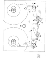
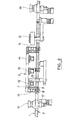
- the drawing shows a tape recorder comprising a base plate 1 made of FORTAL or other similar material having very high dimensional stability.
- This base plate is rectified with very great precision on its underside 2 so as to constitute a single reference plane from which the positions of the important constituents of the plate will be determined.
- a block of heads 6 also precisely machined and very rigid is fixed to the plate by means of screws 7 but the position of this block of heads relative to plate 1 is determined by support screws 8 fixed on the underside of this plate and whose head 9 abuts against the reference face of the plate.
- the rod length of these screws is determined with great precision and it is on the end of their rod that the underside of the head block is supported.
- This block preferably carries an input tape guide 10 and an output tape guide 11 and is equipped with heads 12, 13, 14 adapted to the particular use envisaged, for example, a read head, a head and a recording head. These heads are directed towards the front part of the plate and not towards the winding and unwinding plates of the strip and the part of the plate disposed in front of the block of heads is entirely free.
- Upstream and downstream of this block of heads are disposed respectively an upstream band guide roller 15 and a downstream band guide roller 16 constituted by two identical sub-assemblies.
- Each of these sub-assemblies comprises a support arm 17 mounted oscillating under the base plate, this arm carrying at its free end a rotating roller of suitable construction.
- the axes YY of oscillation of the arms are disposed approximately between the rollers and the axes of the band supports
- These sub-assemblies of band guide rollers are mounted between adjustable stops 18 constituted in the example chosen by two fixed eccentrics on the underside of the plate.
- the belt guide rollers can be associated with tachometric generators making it possible to detect the running speed of the band and coupled to appropriate regulation devices.
- the device is completed by a drive roller 19 mounted on the output member of a motor 20 fixed under the plate, this drive roller being disposed at a short distance from the outlet strip guide, between this guide belt and the downstream belt guide roller.
- a pressure roller 21 In the vicinity of this drive roller 19 is disposed a pressure roller 21 whose role is to apply the strip against the entrainment roller.
- This pressure roller is carried by an oscillating arm 22 of construction similar to that of the two support arms of the belt guide rollers.
- strip release finger 23 disposed in the retracted position behind the strip under the head block and which in the active position allows the strip to be released from this head block.
- This strip release finger is carried by an oscillating arm 24 preferably arranged like the other support arms of the band guide rollers and of the pressure roller.
- actuating the pressure roller and the belt release means are also provided for actuating the pressure roller and the belt release.
- the actuating means of the pressure roller comprise two electromagnets 25, 26 acting in sequence, the first performing a rapid approach movement, while the second is intended to effect a more precise end-of-travel movement.
- the belt release actuator comprises a simple electromagnet 27.
- roller 28 known as a "twister” roller, unique, disposed in the central part of the plate.
- the plate which has just been described and on which the path of the strip is shown in phantom in FIG. 1 has the following features:
Landscapes
- Registering, Tensioning, Guiding Webs, And Rollers Therefor (AREA)
- Decoration Of Textiles (AREA)
- Transducers For Ultrasonic Waves (AREA)
- Obtaining Desirable Characteristics In Audible-Bandwidth Transducers (AREA)
- Audible-Bandwidth Dynamoelectric Transducers Other Than Pickups (AREA)
- Recording Or Reproducing By Magnetic Means (AREA)
- Automatic Assembly (AREA)
Priority Applications (1)
| Application Number | Priority Date | Filing Date | Title |
|---|---|---|---|
| AT83401086T ATE21461T1 (de) | 1982-06-11 | 1983-05-30 | Tonbandgeraetechassis. |
Applications Claiming Priority (2)
| Application Number | Priority Date | Filing Date | Title |
|---|---|---|---|
| FR8210222 | 1982-06-11 | ||
| FR8210222A FR2528606B1 (fr) | 1982-06-11 | 1982-06-11 | Platine de magnetophone |
Publications (2)
| Publication Number | Publication Date |
|---|---|
| EP0097077A1 true EP0097077A1 (de) | 1983-12-28 |
| EP0097077B1 EP0097077B1 (de) | 1986-08-13 |
Family
ID=9274905
Family Applications (1)
| Application Number | Title | Priority Date | Filing Date |
|---|---|---|---|
| EP83401086A Expired EP0097077B1 (de) | 1982-06-11 | 1983-05-30 | Tonbandgerätechassis |
Country Status (4)
| Country | Link |
|---|---|
| EP (1) | EP0097077B1 (de) |
| AT (1) | ATE21461T1 (de) |
| DE (1) | DE3365279D1 (de) |
| FR (1) | FR2528606B1 (de) |
Cited By (2)
| Publication number | Priority date | Publication date | Assignee | Title |
|---|---|---|---|---|
| EP0350054A3 (en) * | 1988-07-08 | 1990-09-05 | Sharp Kabushiki Kaisha | Magnetic recording and reproducing apparatus |
| EP0323188A3 (en) * | 1987-12-25 | 1990-09-12 | Sharp Kabushiki Kaisha | Magnetic recording and reproducing head unit |
Citations (7)
| Publication number | Priority date | Publication date | Assignee | Title |
|---|---|---|---|---|
| FR1058912A (fr) * | 1951-03-13 | 1954-03-19 | Procédé et dispositifs de commande et de régulation automatiques d'un appareil enregistreur répétiteur à ruban magnétique | |
| US2728577A (en) * | 1950-11-09 | 1955-12-27 | Ampro Corp | Magnetic instrument mechanism head |
| US2893653A (en) * | 1956-05-24 | 1959-07-07 | Ampex | Magnetic tape machine |
| US2997547A (en) * | 1956-04-02 | 1961-08-22 | Canadian Patents Dev | Adjustable mountings for magnetic heads and the like |
| US2996948A (en) * | 1956-04-02 | 1961-08-22 | Canadian Patents Dev | Sound recording and reproducing apparatus utilizing perforated magnetic tape |
| US3380681A (en) * | 1966-02-16 | 1968-04-30 | Army Usa | Tension controlled winding apparatus |
| USRE29733E (en) * | 1975-02-10 | 1978-08-15 | T.A.D. Avanti, Inc. | Telephone answering apparatus |
-
1982
- 1982-06-11 FR FR8210222A patent/FR2528606B1/fr not_active Expired
-
1983
- 1983-05-30 DE DE8383401086T patent/DE3365279D1/de not_active Expired
- 1983-05-30 AT AT83401086T patent/ATE21461T1/de not_active IP Right Cessation
- 1983-05-30 EP EP83401086A patent/EP0097077B1/de not_active Expired
Patent Citations (7)
| Publication number | Priority date | Publication date | Assignee | Title |
|---|---|---|---|---|
| US2728577A (en) * | 1950-11-09 | 1955-12-27 | Ampro Corp | Magnetic instrument mechanism head |
| FR1058912A (fr) * | 1951-03-13 | 1954-03-19 | Procédé et dispositifs de commande et de régulation automatiques d'un appareil enregistreur répétiteur à ruban magnétique | |
| US2997547A (en) * | 1956-04-02 | 1961-08-22 | Canadian Patents Dev | Adjustable mountings for magnetic heads and the like |
| US2996948A (en) * | 1956-04-02 | 1961-08-22 | Canadian Patents Dev | Sound recording and reproducing apparatus utilizing perforated magnetic tape |
| US2893653A (en) * | 1956-05-24 | 1959-07-07 | Ampex | Magnetic tape machine |
| US3380681A (en) * | 1966-02-16 | 1968-04-30 | Army Usa | Tension controlled winding apparatus |
| USRE29733E (en) * | 1975-02-10 | 1978-08-15 | T.A.D. Avanti, Inc. | Telephone answering apparatus |
Cited By (2)
| Publication number | Priority date | Publication date | Assignee | Title |
|---|---|---|---|---|
| EP0323188A3 (en) * | 1987-12-25 | 1990-09-12 | Sharp Kabushiki Kaisha | Magnetic recording and reproducing head unit |
| EP0350054A3 (en) * | 1988-07-08 | 1990-09-05 | Sharp Kabushiki Kaisha | Magnetic recording and reproducing apparatus |
Also Published As
| Publication number | Publication date |
|---|---|
| EP0097077B1 (de) | 1986-08-13 |
| DE3365279D1 (en) | 1986-09-18 |
| FR2528606A1 (fr) | 1983-12-16 |
| FR2528606B1 (fr) | 1987-08-28 |
| ATE21461T1 (de) | 1986-08-15 |
Similar Documents
| Publication | Publication Date | Title |
|---|---|---|
| EP0640435B1 (de) | Schleifmaschine | |
| EP0634986B1 (de) | Translations/rotations-fördersystem für tragelement | |
| FR2541226A1 (fr) | Derailleur pour une bicyclette | |
| FR2596496A1 (fr) | Perfectionnements aux tetes de montage orientables et legeres, notamment pour appareils de prises de vue | |
| FR2591466A1 (fr) | Table d'examen a deplacement longitudinal d'un panneau | |
| FR2469982A1 (fr) | Dispositif de positionnement relatif de deux pieces | |
| FR2870934A1 (fr) | Appareil de lecture de contour comportant un palpeur mobile en rotation | |
| EP0097077B1 (de) | Tonbandgerätechassis | |
| CA2106498C (fr) | Dispositif de fabrication de cartes a puces | |
| EP1820647A2 (de) | Maschine und Verfahren zum Markieren von Formteilen | |
| FR2576586A1 (fr) | Machine d'enroulement de bande ou ruban sur une bobine, notamment avec alimentation en continu d'autres bobines | |
| FR2480725A1 (fr) | Machine d'enroulement de materiau en bande, munie de moyens d'immobilisation momentanee des queues de bande | |
| FR2549400A1 (fr) | Machine a rouleaux a border les rubans metalliques et similaires | |
| CH624213A5 (de) | ||
| FR2513422A1 (fr) | Appareil et procede de guidage d'enroulement et de centrage de bande magnetique | |
| EP1336454A1 (de) | Verfahren und Vorrichtung zur Fenstbearbeitung der Lagerfläche eines Werkstücks, insbesondere für die Feinstbearbeitung der Nockenfläche einer Nockenwelle | |
| CH620630A5 (en) | Track for supporting and transporting components for a transfer machine | |
| FR2464793A1 (fr) | Mecanisme d'ejection d'outil et machine equipes d'un tel mecanisme | |
| FR2918652A1 (fr) | Dispositif rotatif de transfert et d'indexation d'objets metalliques, comportant des moyens d'entrainement sans contact. | |
| EP0337864B1 (de) | Brillengestell-Träger für eine Reproduzier-Maschine | |
| FR2694715A1 (fr) | Procédé et appareil de rectification des manetons de villebrequin. | |
| EP0040264A1 (de) | Vorrichtung zum Längsschneiden für eine Maschine zum Wiederaufwickeln von Klebestreifen | |
| EP3684536A1 (de) | Schleifvorrichtung und verfahren | |
| FR2667052A3 (fr) | Dispositif de guidage de materiau souple en forme de feuille. | |
| EP0972609B1 (de) | Haltesystem für eine Werkzeugmaschine |
Legal Events
| Date | Code | Title | Description |
|---|---|---|---|
| PUAI | Public reference made under article 153(3) epc to a published international application that has entered the european phase |
Free format text: ORIGINAL CODE: 0009012 |
|
| AK | Designated contracting states |
Designated state(s): AT BE CH DE GB IT LI NL SE |
|
| 17P | Request for examination filed |
Effective date: 19840222 |
|
| ITF | It: translation for a ep patent filed | ||
| GRAA | (expected) grant |
Free format text: ORIGINAL CODE: 0009210 |
|
| AK | Designated contracting states |
Kind code of ref document: B1 Designated state(s): AT BE CH DE GB IT LI NL SE |
|
| REF | Corresponds to: |
Ref document number: 21461 Country of ref document: AT Date of ref document: 19860815 Kind code of ref document: T |
|
| REF | Corresponds to: |
Ref document number: 3365279 Country of ref document: DE Date of ref document: 19860918 |
|
| PLBE | No opposition filed within time limit |
Free format text: ORIGINAL CODE: 0009261 |
|
| STAA | Information on the status of an ep patent application or granted ep patent |
Free format text: STATUS: NO OPPOSITION FILED WITHIN TIME LIMIT |
|
| 26N | No opposition filed | ||
| PGFP | Annual fee paid to national office [announced via postgrant information from national office to epo] |
Ref country code: SE Payment date: 19890529 Year of fee payment: 7 |
|
| ITTA | It: last paid annual fee | ||
| PGFP | Annual fee paid to national office [announced via postgrant information from national office to epo] |
Ref country code: NL Payment date: 19890531 Year of fee payment: 7 Ref country code: GB Payment date: 19890531 Year of fee payment: 7 |
|
| PGFP | Annual fee paid to national office [announced via postgrant information from national office to epo] |
Ref country code: CH Payment date: 19890608 Year of fee payment: 7 |
|
| PGFP | Annual fee paid to national office [announced via postgrant information from national office to epo] |
Ref country code: DE Payment date: 19890616 Year of fee payment: 7 |
|
| PGFP | Annual fee paid to national office [announced via postgrant information from national office to epo] |
Ref country code: BE Payment date: 19890714 Year of fee payment: 7 |
|
| PGFP | Annual fee paid to national office [announced via postgrant information from national office to epo] |
Ref country code: AT Payment date: 19890811 Year of fee payment: 7 |
|
| PG25 | Lapsed in a contracting state [announced via postgrant information from national office to epo] |
Ref country code: GB Effective date: 19900530 Ref country code: AT Effective date: 19900530 |
|
| PG25 | Lapsed in a contracting state [announced via postgrant information from national office to epo] |
Ref country code: SE Effective date: 19900531 Ref country code: LI Effective date: 19900531 Ref country code: CH Effective date: 19900531 Ref country code: BE Effective date: 19900531 |
|
| BERE | Be: lapsed |
Owner name: MONDIAL ELECTRONIQUE Effective date: 19900531 |
|
| PG25 | Lapsed in a contracting state [announced via postgrant information from national office to epo] |
Ref country code: NL Effective date: 19901201 |
|
| NLV4 | Nl: lapsed or anulled due to non-payment of the annual fee | ||
| GBPC | Gb: european patent ceased through non-payment of renewal fee | ||
| REG | Reference to a national code |
Ref country code: CH Ref legal event code: PL |
|
| PG25 | Lapsed in a contracting state [announced via postgrant information from national office to epo] |
Ref country code: DE Effective date: 19910201 |
|
| EUG | Se: european patent has lapsed |
Ref document number: 83401086.0 Effective date: 19910115 |