EP0097344A2 - Relais thermique à courant excessif - Google Patents
Relais thermique à courant excessif Download PDFInfo
- Publication number
- EP0097344A2 EP0097344A2 EP83105947A EP83105947A EP0097344A2 EP 0097344 A2 EP0097344 A2 EP 0097344A2 EP 83105947 A EP83105947 A EP 83105947A EP 83105947 A EP83105947 A EP 83105947A EP 0097344 A2 EP0097344 A2 EP 0097344A2
- Authority
- EP
- European Patent Office
- Prior art keywords
- overcurrent relay
- relay according
- button
- function selection
- switching element
- Prior art date
- Legal status (The legal status is an assumption and is not a legal conclusion. Google has not performed a legal analysis and makes no representation as to the accuracy of the status listed.)
- Granted
Links
Images



Classifications
-
- H—ELECTRICITY
- H01—ELECTRIC ELEMENTS
- H01H—ELECTRIC SWITCHES; RELAYS; SELECTORS; EMERGENCY PROTECTIVE DEVICES
- H01H71/00—Details of the protective switches or relays covered by groups H01H73/00 - H01H83/00
- H01H71/08—Terminals; Connections
-
- H—ELECTRICITY
- H01—ELECTRIC ELEMENTS
- H01H—ELECTRIC SWITCHES; RELAYS; SELECTORS; EMERGENCY PROTECTIVE DEVICES
- H01H83/00—Protective switches, e.g. circuit-breaking switches, or protective relays operated by abnormal electrical conditions otherwise than solely by excess current
- H01H83/20—Protective switches, e.g. circuit-breaking switches, or protective relays operated by abnormal electrical conditions otherwise than solely by excess current operated by excess current as well as by some other abnormal electrical condition
- H01H83/22—Protective switches, e.g. circuit-breaking switches, or protective relays operated by abnormal electrical conditions otherwise than solely by excess current operated by excess current as well as by some other abnormal electrical condition the other condition being imbalance of two or more currents or voltages
- H01H83/223—Protective switches, e.g. circuit-breaking switches, or protective relays operated by abnormal electrical conditions otherwise than solely by excess current operated by excess current as well as by some other abnormal electrical condition the other condition being imbalance of two or more currents or voltages with bimetal elements
-
- H—ELECTRICITY
- H01—ELECTRIC ELEMENTS
- H01H—ELECTRIC SWITCHES; RELAYS; SELECTORS; EMERGENCY PROTECTIVE DEVICES
- H01H71/00—Details of the protective switches or relays covered by groups H01H73/00 - H01H83/00
- H01H71/08—Terminals; Connections
- H01H2071/086—Low power connections for auxiliary switches, e.g. shunt trip
-
- H—ELECTRICITY
- H01—ELECTRIC ELEMENTS
- H01H—ELECTRIC SWITCHES; RELAYS; SELECTORS; EMERGENCY PROTECTIVE DEVICES
- H01H71/00—Details of the protective switches or relays covered by groups H01H73/00 - H01H83/00
- H01H71/10—Operating or release mechanisms
- H01H2071/109—Operating or release mechanisms with provisions for selecting between automatic or manual reset
-
- H—ELECTRICITY
- H01—ELECTRIC ELEMENTS
- H01H—ELECTRIC SWITCHES; RELAYS; SELECTORS; EMERGENCY PROTECTIVE DEVICES
- H01H71/00—Details of the protective switches or relays covered by groups H01H73/00 - H01H83/00
- H01H71/74—Means for adjusting the conditions under which the device will function to provide protection
- H01H2071/7481—Means for adjusting the conditions under which the device will function to provide protection with indexing means for magnetic or thermal tripping adjustment knob
Definitions
- the invention relates to a thermal overcurrent relay of a type described in the preamble of claim 1.
- the purpose of the invention is the development of an inexpensive, assembly-friendly and user-oriented switching part for a thermal overcurrent relay.
- the auxiliary connections should be arranged in front of the main connections in the most distant level of the assembly level.
- the invention has for its object to provide a simple, inexpensive, assembly-friendly inner and outer switching part structure of a thermal overcurrent relay with respect to the connection positions for auxiliary connections and the inner contact system with a minimal overall volume.
- the special arrangement of the switching system should allow clear positioning of a multifunction button and a cam.
- Special emphasis is placed on a simple lever system from the thermal part to the switching part, whereby this lever system should also include temperature compensation with a straight bimetal which acts on the cam disk via a pick-up lever.
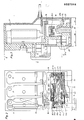
- FIG. 1 shows an overcurrent relay in a front view (position of use, installation position) with the ceiling attached].
- Fig. 2 shows an overcurrent relay according to FIG. 1 in a plan view, with the cover removed.
- Fig. 3 shows a side view of FIG. 2 in section. 4 to 7 show schematic representations, e.g. T. in broken representation, in Direction of the position of use according to FIG. 1.
- FIG. 8 shows one and FIG. 9a, b the other complete connecting piece of an opener switching element.
- Fig. 10a, b shows one and Fig. 11a.b shows the other complete connector of a closer switching element.
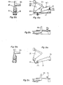
- FIG. 12 a, b, c show in three views a pick-up lever with a compensation bimetal strip.
- 13a, b, c shows in three views the pickup lever according to FIG. 12 without a compensation bimetallic strip.
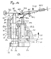
- Fig. 14 shows a multifunction key
- Fig. 15,16 show a function selection button of the multifunction key.
- the overcurrent relay shown in Fig. 1 in the use position is attached to its rear side, for example on a mounting rail, not shown. 10 are main connections and 95.96.97.98 auxiliary connections are designated.
- the attachment takes place in the attachment level 11, the main connections lie in a plane 12 and the auxiliary connections in a parallel plane 13, which, seen in the installed position, lies in front of the plane 12 of the main connections.
- the bimetal relay is closed in FIG. 1 with a cover 16, which also covers the top. 2 shows the relay on an enlarged scale with the cover 16 removed.
- Three bimetallic strips (not shown in more detail) are arranged in three connection chambers 17 and act via a lever 18 on a contact system which is arranged in a control room 19.
- the contact system contains complete connecting pieces 95 ', 96', 97 ', 98' which protrude outwards with corresponding connecting surfaces.
- the switching chamber 19 also contains a lever system for transmitting the movement of the bimetals to the contact arrangement. This lever system contains an angle lever 20, a doffing lever 21 and a straight compensation bimetallic strip 22.
- the multifunction button 14 projects from the outside into the switching chamber and a cam plate 23 on the other.
- the NC switching element is formed from a complete connection piece 96 '(FIG. 9) and a complete connection piece 95' (FIG. 8).
- the complete connector 96 'ent holds a one-piece connector 96'a with a connecting surface 96'b and a riveted opening leaf spring 96'c.
- 96'd one NC contact is designated.
- With 95'c is a shift paddle mounted in a cutting bearing.
- the other NC contact is designated with 95'd.
- the rocker switch 95'c is overmolded with a thermoplastic part 95'e for electrical isolation.
- a tension spring is designated with 95'f.
- the two break contacts 96'd and 95'd form the break contacts 96'd, 95'd.
- the closer switching element consists of a complete connector 97 '(Fig. 10a, b) and a complete connector 98' (Fig. Lla, b).
- 97'd is the one normally open contact.
- the other normally open contact is designated 98'd.
- the two normally open contacts 97'd and 98'd form the normally open contacts 97'd, 98'd.
- the connectors are arranged in the control room 19 such that the individual contacts, seen in the installed position, are arranged one behind the other and are within the range of action of the multifunction button 14.
- This multifunction button 14 has two actuating plungers, namely a function selection button 14a indicated in FIG. 2 and a reset button 14b.
- the function selection button acts on the opening leaf spring 96'c of the opening switching element and the reset button 14b acts on the contact leaf springs 98'c, 97'c and on the rocker switch 95'c. If there is no normally open contact element, the reset button 14b acts directly on the rocker switch 95'c (see FIG. 13).
- connection locations of the auxiliary connections 96, 98, 97 and 95 are designated 1 to 4.
- the auxiliary connections 95-98 are arranged in a row next to one another in the front plane 13, the opener the two outer places 1 and 4 and the closer the two inner places 2 and 3. busy.
- a rib 25 can be placed between the places 1 and 2 and the places 3 and 4 for creepage distance extension without obstructing the screws of the lower main connections 10. No rib is necessary between places 2 and 3.
- Fig. 4 shows a switching arrangement with galvanically isolated opener and closer.
- 95 can also be number 1 and 97 also number 2.
- a changeover can also be achieved by an additional outer line 26 between the connections 95 and 97.
- Fig. 5 shows a circuit as a break contact. The two places 2 and 3 are not occupied.
- Fig. 6 shows a switching arrangement as a changer (direct).
- the connection 98 can also be arranged in place 3. This is better because of the longer spring travel of the contact leaf spring.
- the arrangement according to the invention allows the inner switching part structure to be designed particularly advantageously.
- the connector 95'a can be constructed in one piece and at the same time forms the bearing for the transversely extending tension spring 95'f of the contact system with rocker switch 95'c.
- the connector 95'a extends up to the vicinity of the connector 96 '(Fig. 8 and 2).
- the one-piece connector 96'a is constructed in a U-shape (FIG. 9) and has an opener leaf spring 96'c on the lower leg, which projects under the rocker switch 95'c.
- the design as a break leaf spring 96'c means that when this leaf spring 96'c is actuated, the break contact can be actuated by hand via the multifunction button 14.
- the one-piece contact piece 95'a also contains an extension 95'm for supporting a spring 27, which is supported with its other end on a nose 21c of a doffing lever 21 (see below).
- the closer switching element only contains flat connecting pieces 97'a and 98'a with short extensions, to each of which a contact leaf spring 97'c, 98'c of similar design is attached.
- Contacts 97'd, 98'd attached to the leaf springs are arranged with respect to one another and project together over the rocker switch 95'c and are actuated by the latter when the device is triggered.
- the special arrangement of the connections means that the respective contact leaf springs of the connections 96, 98 and 97 can be given a sufficient length of suspension without this requirement leading to complicated connection parts with manufacturing problems.
- the connecting pieces can be assembled using automatic assembly machines in the order: 96 ', 98', 97 ', 95', the rocker switch 95'c being pressed against an extension 95'l in a stable assembly position via the tension spring 95'f .
- connection piece 95, 96 thus enables a particularly simple and advantageous one-piece design of the connection piece 95'a with the connection surface 95'b and rocker holder and a central arrangement of the NO switching element.
- This has sufficient spring travel for small connecting pieces 97'a, 98'a, which are insignificantly larger than the clamping pressure plates.
- the connecting pieces 97'a and 98'a could even be the same parts if the advantage of the straight contact leaf spring 97'c, 98'c was not rated higher.
- the galvanic separation between the opener and the closer is carried out by a thermoplastic part 95'e (FIG. 2.8) which is known per se and which can be omitted in the case of the exclusive opener version, because the reset button 14b then projects directly onto the rocker 95'c with a screw.
- the function selection button 14a of the multifunction button 14 projects with the screw in any case on the opening leaf spring 96'c, unless one does without a blanking.
- the reset button 14b of the multifunction button 14 serves to reset the tripped overcurrent relay or, in the automatic position, as a stop, so that the switching mechanism of the tension spring 95'f. And switching rocker 95'c switches back to the original position without actuation.
- connection 98 is preferably omitted, the connection 97 preferably remaining arranged next to the connection 95, but being provided with a differently shaped leaf spring which can be switched directly by the rocker switch 95'c.
- this leaf spring must also be position-adjustable by means of the reset button 14b for the different function levels which can be set with the multifunction button.
- the connector 95'a is provided with a locking extension 95'g. 95'h denote fixing holes for housing sleeves.
- the contact rocker 95'c is mounted in a bearing 95'i.
- the feed spring 95'f is mounted on a tension spring cutting edge 95'k.
- a stop 95'1 forms a stable mounting position for the rocker switch 95'c and serves as a stop for this when the opening leaf spring 96'c is actuated with the function selection button 14a during a test switch-off.
- connection piece 96'e the point of application for the screw of the function selection button 14a is designated 96'e.
- the legs of the one-piece U-shaped connection piece 96'a are self-resilient, so that the connection piece is held in the housing by self-resilient clamping (96'f).
- the connection surface 96'b serves to receive a screw with a washer.
- connection piece 97'a has a bent area 97'e.
- This curved area is the only change from the connector 98'a.
- the point of application of the thermoplastic part 95'e of the rocker 95'c is designated by 97'f.
- the leaf spring 97'c is, as with the connection 98, straight, but longer. If you were to use a curved leaf spring here, you could practically use the connector 98'a.
- 97'g are clamping lugs.
- the one-piece contact connector 98'a is provided with clamping lugs 98'e for a tight fit in the housing. With 98'f the point of application of the reset screw of the reset button 14b is designated.
- the arrangement according to the invention also enables a simple lever system for transmitting the distance from the thermal part to the switching part.
- This is served by a doffing lever 21, which is rotatably mounted in the housing at one end 21a and rests at its other end via a nose 21b under spring pressure on the cam surface of a cam disk, which can be actuated by the adjusting button 15.
- a straight compensation bimetallic strip 22 is stary attached with one end.
- a triangular angle lever 20 is rotatably mounted at one corner 20a.
- the angle lever has an extension 20c which acts on the tension spring 95'f.
- the rotary lever has an extension 20e which the thermal lever 18 engages (FIGS. 12a, b, c).
- FIG. 13 shows the same lever arrangement as FIG. 12, but without a compensation bimetallic strip 22.
- the angle lever 20 is rotatably mounted directly on a rigid extension 23 of the pick-up lever 21.
- a spring 27 is supported on a nose 21c.
- the systematic structure of the switching part allows optimal use of the construction volume, with optimum assignment now g of the planes themselves.
- the individual components are arranged in four levels 28 to 31 lying one above the other.
- the connecting pieces lie with their connecting surfaces 95'b to 98'b in the connecting plane 28.
- the closer leaf springs 97'c and 98'c lie one behind the other in the closer plane 29 and pass through the place planes 3,2,1 and 2,1 in the transverse direction and thus get their resilient lengths.
- the opening leaf spring 96'c gets its resilient length because it runs perpendicularly from the connection level 28 through the make level 29 to the opening contact level 30.
- the rocker switch 95'c works in the make and break contacts 29,30.
- the cam plate 23 lies in the free area of the NO and NC contact planes 29, 30 in front of the tension spring 95'f and is therefore located in direct access of the pick-up lever 21 from the transmission plane 31.
- the tension spring 95'f as the center of the make and break contacts level 29,30 is actuated by the angle lever 20 via its extension 20c, while the lever 18 from the thermal range directly onto the active lever 20 can act in the transmission plane 31 because the trigger slide in such a system with a differentiating effect requires such an extended lever in the thermal range.
- the various levels just mentioned can also be seen from FIG. 3.
- the inventive overcurrent relay shows a clear structure compared to known designs with simple to manufacture and easy to assemble individual parts that are optimally arranged and take up very little space.
- FIG. 14 shows a multifunction button 14 with the integrated components of a function selection button 14a and a reset button 14b, which are adjustable in separate openings 29a, 29b of the housing 29.
- An actuating surface 31 of the reset button 14b merges into a flange 32 projecting at right angles.
- a bore 33 in the flange 32 serves to receive the head 34 of the function selection button 14a.
- the reset button 14b projects with a latching tongue 36 arranged on a resilient web 35 into a link 37 of the function selection button 14a.
- the function selection button 14a also has a radial latching projection 38 for engaging in a housing slot 39.
- 40 is a return spring for the reset button.
- Function selection button 14a and reset button 14b contain holes 41, 42 for receiving screws 43, 44, which act on the opening leaf spring 96'c or the rocker switch 95'c. These screws are also used to adjust the contacts. Bimetals are indicated at 45.
- the backdrop 37 extends over part of the circumference and merges into a shortened partial backdrop 37a, forming a step.
- the longitudinal extent of this shortened partial backdrop is equal to the length of the latching tongue 36.
- Locking grooves 37c provided. In the exemplary embodiment according to FIGS. 14 to 16, only one opening switching element 96 ', 95' is arranged. If a closer switching element is also to be provided, this is arranged between the rocker switch 95'c and the end of the reset button 14b or the screw 44 (see FIG. 2).
- Function selection button 14a and reset button 14b are adjustable in the direction 30, moreover the function selection button 14a is also rotatable.
- the function selection button 14a is first inserted into the housing bore 29a and rotated so that the locking projection 38 engages in the slot 39. The function selection button is thus secured against falling out.
- the reset button 14b is then inserted into the housing bore 29b via the function selection button and latches with the latching tongue 36 in the link 37 of the function selection button 14a. So that the reset button on the locking tongue 36 on the radio tion selection button 14a and the function selection button on the radial locking projection 38 is held in the housing 29 against falling out.
- Fig. 14 shows the arrangement in the state with closed contacts 95a, 96'd.
- the function selection button 14a is locked in the slot 39 via its locking projection 38.
- the reset button 14b can be adjusted by the reset stroke 46.
- the latching tongue 36 slides in the link 37. This is the functional level H "(self-locking).
- the rocker switch 95'c assumes the dashed position and remains in this position Even if the bimetals serving as triggers have cooled down again, the reset takes place by actuating the reset button 14b by the relative stroke 46. Since the function selection button 14a is locked in this position, there is no test initiation, ie no loading the opening leaf spring 96'c can be actuated by the function selection button 14a.
- the next function level is reached by turning the function selection button by approximately 30 ° in the direction of rotation 47.
- the locking projection 38 slides out of the slot 39 so that the function selection button 14a is adjustable in the direction 30.
- This function level is called “hand”.
- the reset button and function selector button after passing through the relative stroke 46, can be adjusted together by a test stroke 48 until the reset button 14b stops on the housing 29.
- the latching tongue 36 takes the function selection button 14a with it, the opener leaf spring 96'c being opened by the screw 43 (opener test).
- a next function level is achieved in that, according to FIG. 14, the reset button 14b is pressed by the relative stroke 46 and the function selection button 14a is rotated by a further 30 ° in the direction 47.
- the latching tongue 36 slides into the shortened partial link 37a, so that the function selection button and the reset button are locked together. This is a self-declining position. If the rocker switch 95'c is triggered, it automatically returns to the starting position after the bimetals 45 have been reset. In this position too, the function selection button 14a is unlocked with respect to the housing 29, so that here too, by actuating the function selection button and the reset button together, a test triggering by adjustment by the test stroke 48 is possible.
- a further function level is possible in that the function selection button 14a is turned by a further approximately 30 ° in the direction 47.
- the function selection button 14a is locked again with the housing 29 (38, 39) so that it is no longer possible to initiate a test.
- the self-retracting position is retained since the latching tongue 36 lies further within the shortened partial backdrop 37a and the latching between the function selection button and the reset button is thus maintained (function level "A").
- a further function level “T” (endurance test) can be achieved by pushing the function selection button 14a from the "hand" position up to a housing stop 49 into the interior of the housing and then rotating it in the opposite direction to the direction of rotation 47.
- the locking projection 38 is locked behind a lower housing stop 50. In this position, the normally closed contact is open continuously, even if there is no constant actuation pressure on the keys.
- This function level is particularly suitable for continuous signaling via an additional normally open contact.
- the screws 43, 44 can be used to adjust the contact positions, and in the exemplary embodiment according to FIGS. 14-16 these screws form the ends of the function selection button 14a and the reset button 14b. No adjustment can be made without these screws. In this case, the ends of the function selection button and the reset button only serve as control elements.
- a bore 51 is provided for receiving a lead wire. This means that any actuation can be prevented in the functional positions "II" and "IIand".
- the latching tongue 36 overcomes the latching edges 37b due to its resilient mounting on the web 35, so that a latching effect takes place which prevents an automatic adjustment by vibrations and impacts.
Landscapes
- Switch Cases, Indication, And Locking (AREA)
Applications Claiming Priority (6)
| Application Number | Priority Date | Filing Date | Title |
|---|---|---|---|
| DE3223212 | 1982-06-22 | ||
| DE3223212 | 1982-06-22 | ||
| DE3305646 | 1983-02-18 | ||
| DE19833305646 DE3305646C2 (de) | 1982-06-22 | 1983-02-18 | Thermisches Überstromrelais |
| DE3311329 | 1983-03-29 | ||
| DE19833311329 DE3311329C2 (de) | 1983-03-29 | 1983-03-29 | Thermisches Überstromrelais |
Publications (3)
| Publication Number | Publication Date |
|---|---|
| EP0097344A2 true EP0097344A2 (fr) | 1984-01-04 |
| EP0097344A3 EP0097344A3 (en) | 1987-01-07 |
| EP0097344B1 EP0097344B1 (fr) | 1991-04-17 |
Family
ID=27190183
Family Applications (1)
| Application Number | Title | Priority Date | Filing Date |
|---|---|---|---|
| EP83105947A Expired - Lifetime EP0097344B1 (fr) | 1982-06-22 | 1983-06-17 | Relais thermique à courant excessif |
Country Status (1)
| Country | Link |
|---|---|
| EP (1) | EP0097344B1 (fr) |
Cited By (2)
| Publication number | Priority date | Publication date | Assignee | Title |
|---|---|---|---|---|
| EP0254162A3 (en) * | 1986-07-23 | 1989-12-13 | Siemens Aktiengesellschaft | Overload relay |
| EP0321086A3 (en) * | 1987-12-17 | 1990-10-10 | Eaton Corporation | Overload relay having adaptive differential mechanism |
Family Cites Families (4)
| Publication number | Priority date | Publication date | Assignee | Title |
|---|---|---|---|---|
| FR74574E (fr) * | 1958-12-01 | 1960-12-19 | Perfectionnements aux relais différentiels thermiques de protection électrique | |
| DE2914775B1 (de) * | 1979-04-11 | 1980-07-17 | Siemens Ag | Einrichtung zum Umstellen einer Umschaltkontaktanordnung |
| DE2914776C2 (de) * | 1979-04-11 | 1981-07-02 | Siemens AG, 1000 Berlin und 8000 München | Auslöser für ein thermisches Schutzrelais |
| DE2950438C2 (de) * | 1979-12-14 | 1985-11-14 | Siemens AG, 1000 Berlin und 8000 München | Abdeckhaube für thermisches Schutzrelais |
-
1983
- 1983-06-17 EP EP83105947A patent/EP0097344B1/fr not_active Expired - Lifetime
Cited By (2)
| Publication number | Priority date | Publication date | Assignee | Title |
|---|---|---|---|---|
| EP0254162A3 (en) * | 1986-07-23 | 1989-12-13 | Siemens Aktiengesellschaft | Overload relay |
| EP0321086A3 (en) * | 1987-12-17 | 1990-10-10 | Eaton Corporation | Overload relay having adaptive differential mechanism |
Also Published As
| Publication number | Publication date |
|---|---|
| EP0097344A3 (en) | 1987-01-07 |
| EP0097344B1 (fr) | 1991-04-17 |
Similar Documents
| Publication | Publication Date | Title |
|---|---|---|
| EP0543208B1 (fr) | Disjoncteur de protection avec bascule | |
| DE3411275A1 (de) | Leistungsschalter | |
| EP0268098B1 (fr) | Appareil de commutation électrique, en particulier pour commande de puissance | |
| DE19708609C2 (de) | Schiebeschalter | |
| DE3229280C2 (fr) | ||
| DE20214209U1 (de) | Doppelkreis-Schalteraufbau mit Überlastungsschutz | |
| DE4129938A1 (de) | Druckknopfschalter | |
| DE2832224C2 (fr) | ||
| WO2003007322A1 (fr) | Appareil de connexion a verrouillage de connexion | |
| DE19726149C2 (de) | Schalteranordnung | |
| EP0107152A1 (fr) | Thermostat | |
| DE10237282B4 (de) | Schalter, Druckknopfschalter und Drehhebelschalter | |
| EP0222181A1 (fr) | Disjoncteur de surintensité | |
| DE8904063U1 (de) | Druckknopfbetätigter Überstromschutzschalter | |
| EP0209832A2 (fr) | Disjoncteur de protection à courant excessif actionné par un bouton-poussoir | |
| EP0097344B1 (fr) | Relais thermique à courant excessif | |
| DE3122885C2 (de) | Tastschalter | |
| DE69006865T2 (de) | Umgebungskompensator für thermisches Überlastrelais. | |
| DE10129176C1 (de) | Mehrpoliges Schaltgerät für den Einsatz auf Sammelschienensystemen | |
| DE3011853C2 (de) | Schalteranordnung mit einer Schmelzsicherung mit austauschbarer Sicherungspatrone | |
| DE2728932C2 (de) | Druckschalter | |
| DE3311329A1 (de) | Thermisches ueberstromrelais | |
| DE3334671A1 (de) | Mehrzweckschalter fuer videokameras | |
| DE3305646A1 (de) | Thermisches ueberstromrelais | |
| DE4210714A1 (de) | Vakuumschalter mit einer Stromschleifenanordnung |
Legal Events
| Date | Code | Title | Description |
|---|---|---|---|
| PUAI | Public reference made under article 153(3) epc to a published international application that has entered the european phase |
Free format text: ORIGINAL CODE: 0009012 |
|
| AK | Designated contracting states |
Designated state(s): FR GB IT SE |
|
| PUAL | Search report despatched |
Free format text: ORIGINAL CODE: 0009013 |
|
| AK | Designated contracting states |
Kind code of ref document: A3 Designated state(s): FR GB IT SE |
|
| 17P | Request for examination filed |
Effective date: 19870622 |
|
| 17Q | First examination report despatched |
Effective date: 19881209 |
|
| GRAA | (expected) grant |
Free format text: ORIGINAL CODE: 0009210 |
|
| AK | Designated contracting states |
Kind code of ref document: B1 Designated state(s): FR GB IT SE |
|
| ET | Fr: translation filed | ||
| GBT | Gb: translation of ep patent filed (gb section 77(6)(a)/1977) | ||
| ITF | It: translation for a ep patent filed | ||
| PLBE | No opposition filed within time limit |
Free format text: ORIGINAL CODE: 0009261 |
|
| STAA | Information on the status of an ep patent application or granted ep patent |
Free format text: STATUS: NO OPPOSITION FILED WITHIN TIME LIMIT |
|
| 26N | No opposition filed | ||
| EAL | Se: european patent in force in sweden |
Ref document number: 83105947.2 |
|
| REG | Reference to a national code |
Ref country code: GB Ref legal event code: 732E |
|
| REG | Reference to a national code |
Ref country code: FR Ref legal event code: TP |
|
| PGFP | Annual fee paid to national office [announced via postgrant information from national office to epo] |
Ref country code: FR Payment date: 19970617 Year of fee payment: 15 |
|
| PGFP | Annual fee paid to national office [announced via postgrant information from national office to epo] |
Ref country code: SE Payment date: 19970624 Year of fee payment: 15 |
|
| PG25 | Lapsed in a contracting state [announced via postgrant information from national office to epo] |
Ref country code: SE Free format text: LAPSE BECAUSE OF NON-PAYMENT OF DUE FEES Effective date: 19980618 |
|
| PG25 | Lapsed in a contracting state [announced via postgrant information from national office to epo] |
Ref country code: FR Free format text: LAPSE BECAUSE OF NON-PAYMENT OF DUE FEES Effective date: 19990226 |
|
| EUG | Se: european patent has lapsed |
Ref document number: 83105947.2 |
|
| REG | Reference to a national code |
Ref country code: FR Ref legal event code: ST |
|
| REG | Reference to a national code |
Ref country code: GB Ref legal event code: IF02 |
|
| PGFP | Annual fee paid to national office [announced via postgrant information from national office to epo] |
Ref country code: GB Payment date: 20020527 Year of fee payment: 20 |
|
| PG25 | Lapsed in a contracting state [announced via postgrant information from national office to epo] |
Ref country code: GB Free format text: LAPSE BECAUSE OF EXPIRATION OF PROTECTION Effective date: 20030616 |
|
| REG | Reference to a national code |
Ref country code: GB Ref legal event code: PE20 |