EP0097458A2 - Appareil mélangeur et procédé - Google Patents
Appareil mélangeur et procédé Download PDFInfo
- Publication number
- EP0097458A2 EP0097458A2 EP83303342A EP83303342A EP0097458A2 EP 0097458 A2 EP0097458 A2 EP 0097458A2 EP 83303342 A EP83303342 A EP 83303342A EP 83303342 A EP83303342 A EP 83303342A EP 0097458 A2 EP0097458 A2 EP 0097458A2
- Authority
- EP
- European Patent Office
- Prior art keywords
- selector valves
- component
- valves
- meter
- selector
- Prior art date
- Legal status (The legal status is an assumption and is not a legal conclusion. Google has not performed a legal analysis and makes no representation as to the accuracy of the status listed.)
- Withdrawn
Links
Images
Classifications
-
- B—PERFORMING OPERATIONS; TRANSPORTING
- B67—OPENING, CLOSING OR CLEANING BOTTLES, JARS OR SIMILAR CONTAINERS; LIQUID HANDLING
- B67D—DISPENSING, DELIVERING OR TRANSFERRING LIQUIDS, NOT OTHERWISE PROVIDED FOR
- B67D7/00—Apparatus or devices for transferring liquids from bulk storage containers or reservoirs into vehicles or into portable containers, e.g. for retail sale purposes
- B67D7/06—Details or accessories
- B67D7/74—Devices for mixing two or more different liquids to be transferred
- B67D7/743—Devices for mixing two or more different liquids to be transferred electrically or electro-mechanically operated
-
- B—PERFORMING OPERATIONS; TRANSPORTING
- B01—PHYSICAL OR CHEMICAL PROCESSES OR APPARATUS IN GENERAL
- B01F—MIXING, e.g. DISSOLVING, EMULSIFYING OR DISPERSING
- B01F23/00—Mixing according to the phases to be mixed, e.g. dispersing or emulsifying
- B01F23/40—Mixing liquids with liquids; Emulsifying
- B01F23/49—Mixing systems, i.e. flow charts or diagrams
-
- B—PERFORMING OPERATIONS; TRANSPORTING
- B01—PHYSICAL OR CHEMICAL PROCESSES OR APPARATUS IN GENERAL
- B01F—MIXING, e.g. DISSOLVING, EMULSIFYING OR DISPERSING
- B01F35/00—Accessories for mixers; Auxiliary operations or auxiliary devices; Parts or details of general application
- B01F35/71—Feed mechanisms
- B01F35/712—Feed mechanisms for feeding fluids
-
- B—PERFORMING OPERATIONS; TRANSPORTING
- B01—PHYSICAL OR CHEMICAL PROCESSES OR APPARATUS IN GENERAL
- B01F—MIXING, e.g. DISSOLVING, EMULSIFYING OR DISPERSING
- B01F35/00—Accessories for mixers; Auxiliary operations or auxiliary devices; Parts or details of general application
- B01F35/71—Feed mechanisms
- B01F35/717—Feed mechanisms characterised by the means for feeding the components to the mixer
- B01F35/7176—Feed mechanisms characterised by the means for feeding the components to the mixer using pumps
-
- B—PERFORMING OPERATIONS; TRANSPORTING
- B01—PHYSICAL OR CHEMICAL PROCESSES OR APPARATUS IN GENERAL
- B01F—MIXING, e.g. DISSOLVING, EMULSIFYING OR DISPERSING
- B01F35/00—Accessories for mixers; Auxiliary operations or auxiliary devices; Parts or details of general application
- B01F35/71—Feed mechanisms
- B01F35/717—Feed mechanisms characterised by the means for feeding the components to the mixer
- B01F35/71805—Feed mechanisms characterised by the means for feeding the components to the mixer using valves, gates, orifices or openings
-
- Y—GENERAL TAGGING OF NEW TECHNOLOGICAL DEVELOPMENTS; GENERAL TAGGING OF CROSS-SECTIONAL TECHNOLOGIES SPANNING OVER SEVERAL SECTIONS OF THE IPC; TECHNICAL SUBJECTS COVERED BY FORMER USPC CROSS-REFERENCE ART COLLECTIONS [XRACs] AND DIGESTS
- Y10—TECHNICAL SUBJECTS COVERED BY FORMER USPC
- Y10T—TECHNICAL SUBJECTS COVERED BY FORMER US CLASSIFICATION
- Y10T137/00—Fluid handling
- Y10T137/4238—With cleaner, lubrication added to fluid or liquid sealing at valve interface
- Y10T137/4245—Cleaning or steam sterilizing
-
- Y—GENERAL TAGGING OF NEW TECHNOLOGICAL DEVELOPMENTS; GENERAL TAGGING OF CROSS-SECTIONAL TECHNOLOGIES SPANNING OVER SEVERAL SECTIONS OF THE IPC; TECHNICAL SUBJECTS COVERED BY FORMER USPC CROSS-REFERENCE ART COLLECTIONS [XRACs] AND DIGESTS
- Y10—TECHNICAL SUBJECTS COVERED BY FORMER USPC
- Y10T—TECHNICAL SUBJECTS COVERED BY FORMER US CLASSIFICATION
- Y10T137/00—Fluid handling
- Y10T137/8593—Systems
- Y10T137/87571—Multiple inlet with single outlet
- Y10T137/87676—With flow control
- Y10T137/87684—Valve in each inlet
Definitions
- the present invention relates to a blending apparatus and method therefor.
- the apparatus and method will be described with respect to the blending of petroleum products but is applicable to the blending of other liquid or fluent materials such as, for example, food ingredients and the word "component" should be interpreted to include these materials.
- a batch blending method passes measured quantities of component into, for example, a tank and then mixes them and when the mixing is completed the blended product is passed to a storage tank.
- the measuring of the various components can be-carried out in a number of ways, for example in the case of liquid components by means of valves which may measure volume.
- the gathering of the component materials is often carried out by means of robots.
- Such an apparatus and method has considerable use particularly where relatively small quantities of blended product are to be produced.
- the blended product may be produced by a method known as "in-line" blending in which the components are passed to a single line and are added to that line in a metered manner in accordance with their relative proportions in the final blended product.
- in-line blending process is widely used and although not restricted thereto is particularly desirable when large quantities of blended products are to be produced.
- the same apparatus may be used to produce different blended products by blending different components or by blending the same components in different proportions.
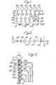
- FIG. 1 illustrates diagrammatically a plan view of a typical installation for in-line blending.
- the components A to F from which the blended products are to be produced are stored separately in respective tanks lOA to IOF.
- Each tank lOA to F is connected by a respective pipeline 11A to F via a stop valve 12A to F, a pump 13A to F (which may be a positive displacement pump), a flow meter 14A to F (which may be a turbine flow meter), a check valve 15A to F, to an injection point 17A to F in a pipeline called a "blend header" 16 having an outlet-20 for the blended product.
- a stop valve 12A to F which may be a positive displacement pump
- a flow meter 14A to F which may be a turbine flow meter
- check valve 15A to F to an injection point 17A to F in a pipeline called a "blend header" 16 having an outlet-20 for the blended product.
- Control apparatus is provided to operate the pumps 13A to F in accordance with a predetermined relation which in general terms will be in proportion to the desired relative proportions of the components in the blended product.
- the rate of addition to the particular component is measured by means of the flow meter 14A to F which can in turn control the pump 13A to F.
- Clearly such an arrangement can be used to produce a wide variety of blended products by varying the proportion of components added from zero upwards. Thus for example in one application it may only be required to blend components A, B and C from tanks 10A, B and C in which case valves 11D, E and F can be closed.
- an individual pump 13A may be connected to different tanks at different times so that there is no need to have a dedicated pump 13 and meter 14 for each component tank.
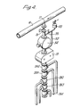
- FIG. 2 shows one of the lines 11A between a hose exchange 18A and the blend header 16. in more detail.
- the hose exchange 18A already referred to, a .further isolating valve 19A, a strainer 21A, the positive displacement pump 13A, an air eliminator 22A, the meter 14A and the check valve 15A.
- these have generally been arranged in a generally horizontal configuration and it will be noted in particular that the strainer 21A and air eliminator 22A by virtue of their design have sumps below the level of the line 11A.
- the strainer 21A protects the downstream pump and meter, and the air eliminator 22A ensures disposal of air "slugs" and being the highest point in the metering stream the normal vent is converted to allow blowback of the unmetered liquid back to storage.
- the present invention provides an in-line blender for blending components in the form of liquid or other fluent materials comprising a pipeline, a plurality of injection points in said pipeline, characterised in that there is provided a respective set of selector valves in series adjacent to one another connected to each injection point, each selector valve being movable between two positions, in a first position connecting an outlet of that valve with the supply of a respective one component and in a second position interconnecting the selector valves which are downstream and upstream of it, the selector valves of each set of selector valves which is furthest downstream being connected to a metering apparatus and thence to.the associated injection point, and means to control the selector valves whereby, during operation, only one of the selector valves in each set of selector valves is in the first position and the others are in the second position so that, for each set of selector valves, the component from said only one of the selector valves is metered to the associated injection point.
- the selector valves are preferably "T" valves and the selector valves in each set are preferably arranged vertically above one another. This provides a conveniently compact arrangement and also means that if air is inserted from above the selector valves during cleaning of the apparatus, the component in the relative selector valve can be substantially completely removed by the air supply and any material clinging to the.walls of the selector valves will naturally drain downwards and out of the system.
- a drain cap can, if required, be provided at the bottom of the vertical arrangement of selector valves to further assist draining of the system.
- a positive displacement pump and a meter are preferably connected vertically above each set of selector valves.
- a bypass may be mounted around each meter so that in use the majority of air provided downstream of the meter to clean the system will bypass the meter and when the system is filling up again the majority of component will initially pass around the meter-
- each meter there may be provided a member through which air may be inserted as described above and also through which the air which has been inserted is vented when the apparatus is reconnected to pass the component to be blended to prevent the air passing into the pipeline.
- a strainer is provided between each selector valve and its supply of component. In this way the strainer does not have to be cleaned of component each time the.component is changed.
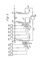
- each selector valve 26G to K each in the form of "T" valves having an upper outlet 27, a bottom inlet 28, and a side inlet 29.
- the upper outlet 27 and bottom inlet 28 of successive valves 26 are connected together.
- the side inlet 29 of each selector valve 26 is connected by means of a respective permanently positioned line 31 via an air eliminator 30 (see Figure 5) and a strainer 35 (see Figure 5) with a component tank 10.
- one or more of the selector valves 26 may be connected to a hose exchange 18.
- the upper outlet 27 of the upper selector valve 26G is directly connected to the-positive.displacement pump 13 and the upper outlet of the positive displacement pump 13 is connected to the meter 14.
- the upper outlet of the meter 14 is connected with the check valve 15 and hence to the injection point 17A in the blend header 16.
- a bypass 32 is provided around the meter 14 and connected to the bypass 32 is the air eliminator 22, the air eliminator being arranged so as to be above the meter 14.
- a valve 33 is provided in the bypass 32 between the air. eliminator 22 and the check valve 15. There may if desired be a drain outlet 34 at the bottom of the stack of selector valves 26.
- the selector valves 26 may be hand operated but we prefer that they are motor driven, the motors of each selector valve 26 being controlled by a control unit 36 via control lines 37.
- the selector valves 26G, H J and K are set by hand or by control means 36 in the positions shown in which their bottom inlets 28 and upper outlets 27 are interconnected.
- the selector valve 26I is controlled so as to interconnect the side inlet 29I to its upper outlet 27I.
- component I can flow from component tank 101 through a strainer, through the side inlet 29I of a selector valve 261 out of the upper outlet 27I of selector valve 26I, and through selector valves 26H and 26G to the pump 13 where it is pumped through the meter 14 and valve 15 to the injection point 17A.
- the metering and control of the positive displacement pump is carried out as normal in in-line blending.
- valve 26I After a predetermined period of time the valve 26I is controlled so as to rotate and interconnect its bottom inlet 28I and upper outlet 271. If desired any further component I can be drained out of the system through the drain outlet 34. In normal use this will not be necessary and the valve 26J is then rotated so as to interconnect its side inlet 29J and upper outlet 27J to allow component from tank lOJ to pass through the pump 13. This operation is initially carried out by allowing air which is in the system to bleed out through the air eliminator 22. It will be understood therefore that component J will initially pass up through the pump 13 and bypass the meter 14 through the bypass 32 to the air eliminator.22.
- valves 33 and 15 can be opened to begin inserting component J into the blend header 16 at the injection point 17A. It will be understood that any of the component I which is initially washed off the wall by component J will pass into the sump of the air eliminator 22 and remain there until the supply of component is changed once again when the air supplied to the air eliminator 22 will tend to blow this contaminated mixture back.
- selector valve 26K can be connected to a hose connector rather than to a particular tank.
- strainer 35 is no longer immediately adjacent the pump and can be provided in the line feeding to the relevant side inlets 29 of the selector valves 26.
- the apparatus lends itself to automatic control since the selector valves 26 are motor operated and can be controlled by means of the central control means 36 without the necessity to deal with a hose exchange. Because of the vertical arrangement of the selector valves pump and meter, the component can be allowed to drain away and the supply of air to the air eliminator 22 will effectively push back the component.
Landscapes
- Chemical & Material Sciences (AREA)
- Chemical Kinetics & Catalysis (AREA)
- Engineering & Computer Science (AREA)
- Mechanical Engineering (AREA)
- Accessories For Mixers (AREA)
- Consolidation Of Soil By Introduction Of Solidifying Substances Into Soil (AREA)
- Processing And Handling Of Plastics And Other Materials For Molding In General (AREA)
Applications Claiming Priority (2)
| Application Number | Priority Date | Filing Date | Title |
|---|---|---|---|
| GB8217442 | 1982-06-16 | ||
| GB08217442A GB2121695B (en) | 1982-06-16 | 1982-06-16 | Flow mixing |
Publications (2)
| Publication Number | Publication Date |
|---|---|
| EP0097458A2 true EP0097458A2 (fr) | 1984-01-04 |
| EP0097458A3 EP0097458A3 (fr) | 1986-07-02 |
Family
ID=10531080
Family Applications (1)
| Application Number | Title | Priority Date | Filing Date |
|---|---|---|---|
| EP83303342A Withdrawn EP0097458A3 (fr) | 1982-06-16 | 1983-06-09 | Appareil mélangeur et procédé |
Country Status (3)
| Country | Link |
|---|---|
| US (1) | US4488570A (fr) |
| EP (1) | EP0097458A3 (fr) |
| GB (1) | GB2121695B (fr) |
Cited By (16)
| Publication number | Priority date | Publication date | Assignee | Title |
|---|---|---|---|---|
| EP0172000A3 (en) * | 1984-08-09 | 1986-12-30 | John D. Kirschmann | Chemical dispensing system |
| FR2587738A1 (fr) * | 1985-09-25 | 1987-03-27 | Saint Gobain Isover | Reparation des compositions d'encollage pour feutres de fibres minerales |
| EP0245667A1 (fr) * | 1986-05-10 | 1987-11-19 | Edeleanu Gesellschaft mbH | Dispositif de pesage pour peser des partiens à melanger |
| FR2605899A1 (fr) * | 1986-10-29 | 1988-05-06 | Elf France | Procede et installation d'injection d'un additif dans un produit principal |
| WO1988006958A1 (fr) * | 1987-03-12 | 1988-09-22 | Thermal Structures Limited | Appareil et procede de production de materiaux expanses |
| EP0471268A1 (fr) * | 1990-08-06 | 1992-02-19 | Fuji Photo Film Co., Ltd. | Dispositif pour injecter plusieurs liquides dans un récipient |
| EP0433041A3 (en) * | 1989-12-15 | 1992-05-27 | Gilbarco Inc. | A fuel dispenser system |
| US5203366A (en) * | 1992-02-05 | 1993-04-20 | Ecolab Inc. | Apparatus and method for mixing and dispensing chemical concentrates at point of use |
| EP0566976A1 (fr) * | 1992-04-24 | 1993-10-27 | ULTRAKUST electronic GmbH | Procédé et dispositif de décharge de liquides ou gaz |
| EP0768325A3 (fr) * | 1995-10-16 | 1997-04-23 | Shell Internationale Researchmaatschappij B.V. | Mélanges de polyols |
| WO2005033168A1 (fr) | 2003-09-29 | 2005-04-14 | Basf Aktiengesellschaft | Procede de production de melanges de polyols |
| WO2020035395A1 (fr) | 2018-08-16 | 2020-02-20 | Basf Se | Systèmes de mousses polyuréthanes en aérosol actionnés de manière écologique |
| WO2020035382A1 (fr) | 2018-08-16 | 2020-02-20 | Basf Se | Composition de polyisocyanate, mousse de polyuréthane obtenue à partir de celle-ci et son utilisation |
| WO2021229044A1 (fr) | 2020-05-14 | 2021-11-18 | Basf Se | Mousses de polyuréthane à dissipation électrique et leur utilisation dans des dispositifs anti-érosion de tranchée ou des coussins de pipeline |
| WO2021259832A1 (fr) | 2020-06-22 | 2021-12-30 | Basf Se | Mousses de polyuréthane élastomères viscoélastiques, leur procédé de préparation et leur utilisation |
| WO2023036801A1 (fr) | 2021-09-07 | 2023-03-16 | Basf Se | Mousses de polyuréthane à base de monomère ionique et leur utilisation dans des barrages de tranchée ou des coussins de support de canalisation ou un matériau thermiquement isolant |
Families Citing this family (22)
| Publication number | Priority date | Publication date | Assignee | Title |
|---|---|---|---|---|
| US5102228A (en) * | 1988-03-09 | 1992-04-07 | Thermal Structures Limited | Apparatus and method for producing foamed materials |
| DE3814917A1 (de) * | 1988-05-03 | 1989-11-16 | Kernforschungsz Karlsruhe | Gasmischer zur erzeugung eines kontinuierlichen gasmischstromes |
| US10040041B2 (en) | 2015-07-09 | 2018-08-07 | Cameron International Corporation | Crude oil blending using total boiling point analysis |
| US9909415B2 (en) | 2015-11-20 | 2018-03-06 | Cameron International Corporation | Method and apparatus for analyzing mixing of a fluid in a conduit |
| US11607654B2 (en) | 2019-12-30 | 2023-03-21 | Marathon Petroleum Company Lp | Methods and systems for in-line mixing of hydrocarbon liquids |
| CA3104319C (fr) | 2019-12-30 | 2023-01-24 | Marathon Petroleum Company Lp | Procedes et systemes de gestion du refoulement dans le melange en conduite de liquides d'hydrocarbures |
| CA3103416C (fr) | 2019-12-30 | 2022-01-25 | Marathon Petroleum Company Lp | Procedes et systemes de melange en conduite de liquides d`hydrocarbures |
| US11559774B2 (en) | 2019-12-30 | 2023-01-24 | Marathon Petroleum Company Lp | Methods and systems for operating a pump at an efficiency point |
| US11655940B2 (en) | 2021-03-16 | 2023-05-23 | Marathon Petroleum Company Lp | Systems and methods for transporting fuel and carbon dioxide in a dual fluid vessel |
| US12012883B2 (en) | 2021-03-16 | 2024-06-18 | Marathon Petroleum Company Lp | Systems and methods for backhaul transportation of liquefied gas and CO2 using liquefied gas carriers |
| US11578836B2 (en) | 2021-03-16 | 2023-02-14 | Marathon Petroleum Company Lp | Scalable greenhouse gas capture systems and methods |
| US11578638B2 (en) | 2021-03-16 | 2023-02-14 | Marathon Petroleum Company Lp | Scalable greenhouse gas capture systems and methods |
| US12043905B2 (en) | 2021-08-26 | 2024-07-23 | Marathon Petroleum Company Lp | Electrode watering assemblies and methods for maintaining cathodic monitoring of structures |
| US12129559B2 (en) | 2021-08-26 | 2024-10-29 | Marathon Petroleum Company Lp | Test station assemblies for monitoring cathodic protection of structures and related methods |
| US11447877B1 (en) | 2021-08-26 | 2022-09-20 | Marathon Petroleum Company Lp | Assemblies and methods for monitoring cathodic protection of structures |
| US12180597B2 (en) | 2021-08-26 | 2024-12-31 | Marathon Petroleum Company Lp | Test station assemblies for monitoring cathodic protection of structures and related methods |
| US11686070B1 (en) | 2022-05-04 | 2023-06-27 | Marathon Petroleum Company Lp | Systems, methods, and controllers to enhance heavy equipment warning |
| US12012082B1 (en) | 2022-12-30 | 2024-06-18 | Marathon Petroleum Company Lp | Systems and methods for a hydraulic vent interlock |
| US12006014B1 (en) | 2023-02-18 | 2024-06-11 | Marathon Petroleum Company Lp | Exhaust vent hoods for marine vessels and related methods |
| US12043361B1 (en) | 2023-02-18 | 2024-07-23 | Marathon Petroleum Company Lp | Exhaust handling systems for marine vessels and related methods |
| US12297965B2 (en) | 2023-08-09 | 2025-05-13 | Marathon Petroleum Company Lp | Systems and methods for mixing hydrogen with natural gas |
| US12597151B2 (en) | 2023-09-18 | 2026-04-07 | Marathon Petroleum Company Lp | Systems and methods to determine vegetation encroachment along a right-of-way |
Family Cites Families (10)
| Publication number | Priority date | Publication date | Assignee | Title |
|---|---|---|---|---|
| US564383A (en) * | 1896-07-21 | Self-measuring vessel | ||
| GB1047251A (fr) * | ||||
| GB648091A (en) * | 1948-08-03 | 1950-12-28 | Simmonds Aerocessories Inc | Improvements in flow combiner or precision apparatus for blending liquids |
| DE974446C (de) * | 1952-10-29 | 1960-12-29 | Schenk Filterbau Gmbh | Einrichtung zur Fluessigkeitsfiltration unter Zusatz von Filterhilfsmitteln |
| US3870233A (en) * | 1973-09-12 | 1975-03-11 | Nordson Corp | Color change of electrostatic spray apparatus |
| US4142860A (en) * | 1976-06-23 | 1979-03-06 | Mayeaux Donald P | Apparatus for producing a calibration sample for analytical instrumentation |
| US4163523A (en) * | 1976-12-15 | 1979-08-07 | Vincent Raymond A | Multicolor paint dispensing system having a pressure responsive color change valve |
| FR2401372A1 (fr) * | 1977-08-22 | 1979-03-23 | Renault | Vanne de changement de teinte pour machine a peindre automatisee |
| US4323004A (en) * | 1980-06-02 | 1982-04-06 | Sereda Alexandr I | Installation for preparing multicomponent liquid mixes in production of strong alcoholic liquors |
| JPS6051867B2 (ja) * | 1980-08-04 | 1985-11-15 | 日本ランズバ−グ株式会社 | 塗料色替え方法 |
-
1982
- 1982-06-16 GB GB08217442A patent/GB2121695B/en not_active Expired
-
1983
- 1983-06-09 EP EP83303342A patent/EP0097458A3/fr not_active Withdrawn
- 1983-06-15 US US06/504,433 patent/US4488570A/en not_active Expired - Fee Related
Cited By (22)
| Publication number | Priority date | Publication date | Assignee | Title |
|---|---|---|---|---|
| EP0172000A3 (en) * | 1984-08-09 | 1986-12-30 | John D. Kirschmann | Chemical dispensing system |
| AU591067B2 (en) * | 1984-08-09 | 1989-11-30 | John D. Kirschmann | Chemical dispensing system |
| FR2587738A1 (fr) * | 1985-09-25 | 1987-03-27 | Saint Gobain Isover | Reparation des compositions d'encollage pour feutres de fibres minerales |
| EP0245667A1 (fr) * | 1986-05-10 | 1987-11-19 | Edeleanu Gesellschaft mbH | Dispositif de pesage pour peser des partiens à melanger |
| FR2605899A1 (fr) * | 1986-10-29 | 1988-05-06 | Elf France | Procede et installation d'injection d'un additif dans un produit principal |
| EP0269490A1 (fr) * | 1986-10-29 | 1988-06-01 | ELF FRANCE, Société Anonyme dite: | Procédé et installation d'injection d'un additif dans un produit principal |
| WO1988006958A1 (fr) * | 1987-03-12 | 1988-09-22 | Thermal Structures Limited | Appareil et procede de production de materiaux expanses |
| EP0433041A3 (en) * | 1989-12-15 | 1992-05-27 | Gilbarco Inc. | A fuel dispenser system |
| EP0471268A1 (fr) * | 1990-08-06 | 1992-02-19 | Fuji Photo Film Co., Ltd. | Dispositif pour injecter plusieurs liquides dans un récipient |
| WO1993015828A1 (fr) * | 1992-02-05 | 1993-08-19 | Ecolab Inc. | Appareil servant a melanger et a distribuer des concentres chimiques |
| US5203366A (en) * | 1992-02-05 | 1993-04-20 | Ecolab Inc. | Apparatus and method for mixing and dispensing chemical concentrates at point of use |
| EP0566976A1 (fr) * | 1992-04-24 | 1993-10-27 | ULTRAKUST electronic GmbH | Procédé et dispositif de décharge de liquides ou gaz |
| EP0768325A3 (fr) * | 1995-10-16 | 1997-04-23 | Shell Internationale Researchmaatschappij B.V. | Mélanges de polyols |
| RU2166520C2 (ru) * | 1995-10-16 | 2001-05-10 | Шелл Интернэшнл Рисерч Маатсхаппий Б.В. | Способ получения смеси полиолов и смесь полиолов |
| CN1087183C (zh) * | 1995-10-16 | 2002-07-10 | 国际壳牌研究有限公司 | 共混多羟基化合物 |
| WO2005033168A1 (fr) | 2003-09-29 | 2005-04-14 | Basf Aktiengesellschaft | Procede de production de melanges de polyols |
| WO2020035395A1 (fr) | 2018-08-16 | 2020-02-20 | Basf Se | Systèmes de mousses polyuréthanes en aérosol actionnés de manière écologique |
| WO2020035382A1 (fr) | 2018-08-16 | 2020-02-20 | Basf Se | Composition de polyisocyanate, mousse de polyuréthane obtenue à partir de celle-ci et son utilisation |
| WO2021229044A1 (fr) | 2020-05-14 | 2021-11-18 | Basf Se | Mousses de polyuréthane à dissipation électrique et leur utilisation dans des dispositifs anti-érosion de tranchée ou des coussins de pipeline |
| WO2021259832A1 (fr) | 2020-06-22 | 2021-12-30 | Basf Se | Mousses de polyuréthane élastomères viscoélastiques, leur procédé de préparation et leur utilisation |
| US12552894B2 (en) | 2020-06-22 | 2026-02-17 | Basf Se | Viscoelastic elastomeric polyurethane foams, process for preparing them and use thereof |
| WO2023036801A1 (fr) | 2021-09-07 | 2023-03-16 | Basf Se | Mousses de polyuréthane à base de monomère ionique et leur utilisation dans des barrages de tranchée ou des coussins de support de canalisation ou un matériau thermiquement isolant |
Also Published As
| Publication number | Publication date |
|---|---|
| US4488570A (en) | 1984-12-18 |
| GB2121695B (en) | 1985-07-10 |
| GB2121695A (en) | 1984-01-04 |
| EP0097458A3 (fr) | 1986-07-02 |
Similar Documents
| Publication | Publication Date | Title |
|---|---|---|
| US4488570A (en) | Blending apparatus and method | |
| DE29814318U1 (de) | Vorrichtung für die Abgabe von Getränken | |
| DE2151066A1 (de) | Maschine zum Herstellen von Eiskrem | |
| EP0041120B1 (fr) | Appareil pour mesurer les quantités de lait et procédé pour déterminer les quantités de lait tirées d'une vache au cours de la traite | |
| EP0209967B1 (fr) | Système de nettoyage d'un injecteur de combustible | |
| DE19733715C1 (de) | Verfahren und Anlage zur Abgabe von Flüssigkeit aus einem mehrere Kammern enthaltenden Tankwagen | |
| DE102006001866C5 (de) | Verfahren und Vorrichtung zur Abgabe eines Fluides aus einem Tank | |
| US6330934B1 (en) | Complete fluid exchange system for automatic transmissions | |
| DE68904452T2 (de) | Kochanlage. | |
| DE1957501C3 (de) | Vorrichtung zum Mischen von zwei oder mehreren Flüssigkeiten in einem bestimmten Mengenverhältnis | |
| DE69324275T2 (de) | Durchfluss- und volumengeregelte tankreinigungsvorrichtung | |
| DE3735513C2 (de) | Anordnung zum steuern einer essiggaeranlage | |
| DE3023823C2 (fr) | ||
| AU752199B2 (en) | Method and device for mixing fluids in a duct | |
| DE10008318B4 (de) | Wasserführendes Haushaltsgerät mit einem Entleerungssystem sowie Verfahren zur Befüllung und zur Überwachung einer Entleerung eines Arbeitsbehälters | |
| DE4226871C1 (de) | Anordnung zur Wasserförderung mit Wasseraufbereitung im Aquifer | |
| EP1352599A1 (fr) | Appareil pour boisson | |
| DE2353916C2 (de) | Vorrichtung zum Fördern und gleichzeitigen Volumenmessen von Chargen von Flüssigkeiten | |
| DE102004053921A1 (de) | Dosiereinrichtung zur Beigabe von Zusatzstoffen in eine Mischung | |
| DE19505229C2 (de) | Apparatur für Flüssigkeitsabgabeanlagen zum Betrieb mit unterschiedlichen Flüssigkeiten | |
| US4801471A (en) | Closed circuit beverage processing with accumulator | |
| DE4438434C1 (de) | Vorrichtung zur Entnahme einer Probe in einer Milchsammelanlage | |
| DE3930181C2 (fr) | ||
| DE3119340A1 (de) | "waschmaschine mit einer elektrisch antreibbaren laugenpumpe" | |
| EP0519114B1 (fr) | Procédé et dispositif de préparation et de distribution à des auges d'aliment semi-liquide pour animaux |
Legal Events
| Date | Code | Title | Description |
|---|---|---|---|
| PUAI | Public reference made under article 153(3) epc to a published international application that has entered the european phase |
Free format text: ORIGINAL CODE: 0009012 |
|
| AK | Designated contracting states |
Designated state(s): BE DE FR IT NL |
|
| PUAL | Search report despatched |
Free format text: ORIGINAL CODE: 0009013 |
|
| AK | Designated contracting states |
Kind code of ref document: A3 Designated state(s): BE DE FR IT NL |
|
| STAA | Information on the status of an ep patent application or granted ep patent |
Free format text: STATUS: THE APPLICATION IS DEEMED TO BE WITHDRAWN |
|
| 18D | Application deemed to be withdrawn |
Effective date: 19870105 |
|
| RIN1 | Information on inventor provided before grant (corrected) |
Inventor name: JISKOOT, JOOST JAKOB |