EP0097532B1 - Dispositif de pesage combinatoire - Google Patents
Dispositif de pesage combinatoire Download PDFInfo
- Publication number
- EP0097532B1 EP0097532B1 EP83303579A EP83303579A EP0097532B1 EP 0097532 B1 EP0097532 B1 EP 0097532B1 EP 83303579 A EP83303579 A EP 83303579A EP 83303579 A EP83303579 A EP 83303579A EP 0097532 B1 EP0097532 B1 EP 0097532B1
- Authority
- EP
- European Patent Office
- Prior art keywords
- articles
- weighing
- weight
- charging
- rough
- Prior art date
- Legal status (The legal status is an assumption and is not a legal conclusion. Google has not performed a legal analysis and makes no representation as to the accuracy of the status listed.)
- Expired
Links
- 238000005303 weighing Methods 0.000 title claims description 289
- 238000007599 discharging Methods 0.000 claims description 6
- 238000012856 packing Methods 0.000 description 23
- 230000004044 response Effects 0.000 description 20
- 238000000034 method Methods 0.000 description 17
- 230000008569 process Effects 0.000 description 17
- 239000006185 dispersion Substances 0.000 description 16
- 238000010586 diagram Methods 0.000 description 11
- 230000000694 effects Effects 0.000 description 8
- 238000009434 installation Methods 0.000 description 3
- 230000002093 peripheral effect Effects 0.000 description 3
- 230000005484 gravity Effects 0.000 description 2
- 230000007246 mechanism Effects 0.000 description 2
- 238000012545 processing Methods 0.000 description 2
- 238000012546 transfer Methods 0.000 description 2
- 240000004543 Vicia ervilia Species 0.000 description 1
- 230000008901 benefit Effects 0.000 description 1
- 230000005540 biological transmission Effects 0.000 description 1
- 238000013479 data entry Methods 0.000 description 1
- 235000013305 food Nutrition 0.000 description 1
- 235000013611 frozen food Nutrition 0.000 description 1
- 239000000463 material Substances 0.000 description 1
- 238000012986 modification Methods 0.000 description 1
- 230000004048 modification Effects 0.000 description 1
Images


Classifications
-
- G—PHYSICS
- G01—MEASURING; TESTING
- G01G—WEIGHING
- G01G13/00—Weighing apparatus with automatic feed or discharge for weighing-out batches of material
- G01G13/24—Weighing mechanism control arrangements for automatic feed or discharge
- G01G13/242—Twin weighing apparatus; weighing apparatus using single load carrier and a plurality of weigh pans coupled alternately with the load carrier; weighing apparatus with two or more alternatively used weighing devices
-
- G—PHYSICS
- G01—MEASURING; TESTING
- G01G—WEIGHING
- G01G13/00—Weighing apparatus with automatic feed or discharge for weighing-out batches of material
- G01G13/16—Means for automatically discharging weigh receptacles under control of the weighing mechanism
-
- G—PHYSICS
- G01—MEASURING; TESTING
- G01G—WEIGHING
- G01G19/00—Weighing apparatus or methods adapted for special purposes not provided for in the preceding groups
- G01G19/387—Weighing apparatus or methods adapted for special purposes not provided for in the preceding groups for combinatorial weighing, i.e. selecting a combination of articles whose total weight or number is closest to a desired value
- G01G19/393—Weighing apparatus or methods adapted for special purposes not provided for in the preceding groups for combinatorial weighing, i.e. selecting a combination of articles whose total weight or number is closest to a desired value using two or more weighing units
Definitions
- the present invention relates to a combinatorial weighing apparatus.
- a combinatorial weighing operation is effected to select a combination of weighing machines which hold a total combined weight of articles equal to a target weight, or closest to that target weight within a preset allowable weight range.
- the articles from the weighing machines of the selected combination are then discharged and new articles are subsequently supplied to the emptied weighing machines.
- the above cycle of operation is repeated to perform a continuous automatic combinatorial weighing operation.
- One solution to the above mentioned problems proposes the use of two weighing apparatuses.
- One of the weighing apparatuses weighs and discharges a quantity of articles which have a total combined weight smaller than a target weight. Thereafter, the other weighing apparatus adds further articles to the discharged articles to bring the batch up to the correct target weight.
- This system is based on the principle that articles can be discharged more efficiently by being divided into two groups than by being processed in one batch.
- this system requires two article supply lines, with the result that the overall arrangement becomes large in size and the area required for installation is increased.
- weighing apparatus for weighing out successive quantities of articles, comprising a plurality of weighing machines for providing respective batch weight measure of batches of articles held respectively by those machines, and combination computation means for combining the said batch weight measures to find an acceptable combination of weighing machines holding a total combined weight of articles equal or closest to the difference in weight between a previously weighed out initial quantity of articles and a preselected target weight for a desired quantity of the articles, whereupon the machines of the acceptable combination found are caused to discharge their article batches to be combined with the said initial quantity; characterised by conveying means for moving a first container from a rough charging position, at which it receives such an initial quantity of articles, to a corrective charging position for receiving the articles discharged from the said acceptable combination, and also characterized in that, after the said acceptable combination of the said weighing machines has been found, one or more other machines of the said plurality are employed to weigh out a second initial quantity of articles, into a second container which is then moved by the conveying means from the said rough charging position to the
- US-4,313,507 discloses weighing apparatus for weighing out successive quantities of articles, comprising a plurality of weighing machines for providing respective batch weight measures of batches of articles held respectively by those machines, and combination computation means for combining the said batch weight measures to find an acceptable combination of weighing machines holding a total combined weight of articles equal to or closest to the difference in weight between a previously weighed out initial quantity of articles and a preselected target weight for a desired quantity of the articles; in which the machines of the acceptable combination found are caused to discharge their article batches to be combined with the said initial quantity.
- the apparatus of US ⁇ 4,313,507 is less efficient than apparatus embodying the present invention, in that it provides a discontinuous supply of desired quantities, whereas apparatus embodying the present invention provides a continuous flow of filled containers, some of which are receiving initial "rough charging" batches while others further downstream are being topped up with corrective charging batches. Furthermore, according to the present invention, while a container is being conveyed to a position where a corrective charging batch will be added thereto, all the empty weighing machines of the apparatus are replenished with articles before a corrective charging batch is selected.
- Fig. 1 shows a combinatorial weighing apparatus (not embodying the present invention) including a main article supply unit 11 for supplying articles to be weighed to a plurality (n) of weighing sections 12A, 12B, ... so as to be distributed radially outwardly.
- the main supply unit 11 is of a vibratory conveyance type which is vibratable for a prescribed period of time to supply articles into the weighing sections.
- the weighing sections 12A, 12B, ..., only two of which are shown in Fig. 1, are positioned radially outwardly of the main supply unit 11.
- Each of the weighing sections 12A, 12B, ..., comprises a dispersion supply unit 12a, a pool hopper 12b, a pool hopper gate 12c, a weighing hopper 12d, a weight detector 12e, and a weighing hopper gate 12f.
- the dispersion supply unit 12a comprises an independently vibratable feeder conveyor, or an independently actuable shutter device, for charging articles into the pool hopper 12b disposed below the dispersion supply unit 12a.
- the pool hopper 12b is equipped with the pool hopper gate 12c which, when opened, allows the articles to be discharged from the pool hopper 12b into the weighing hopper 12d.
- the weighing hopper 12d is operatively associated with the weight detector 12e which measures the weight of the article batch held by the weighing hopper 12d, the measued weight being supplied to a combinatorial computing unit (described later on).
- the weighing hopper gate 12f on the weighing hopper 12d is opened by a command from a drive control unit (not shown in Fig. 1) for discharging the articles from the weighing hopper.
- the weighing hopper 12d, the weighing hopper gate 12f, and the weight detector 12e together constitute a weighing machine. Some (m) of the weighing sections 12A, 12B, ... are preselected as giving "rough" weights, while the other weighing sections erve to select a combination of weighing machines which hold a total combined weight equal or closest to a corrective charging weight.
- the weighing section 12A will hereinafter be described as a corrective charging section, and the weighing section 12B as a rough charging section.
- the articles discharged from the weighing machines are collected by a chute 13 downwardly to a central position.
- the chute 13 is of a pyramidal funnel shape for collecting the articles discharged into an outer peripheral edge of the chute 13 by gravity or forcibly by a scraper (not shown) downwardly toward the central portion thereof.
- a timing hopper 14 is located below the chute 13 for temporarily storing the articles collected by the chute 13 and then charging the articles into a container located outside the weighing apparatus in response to a discharge signal issued from a packing machine or other external source.
- Containers B1, B2, B3, ... are arranged in a row to pass successively through a point P (immediately below the timing hopper) where articles are charged from the timing hopper 14 into one of the containers.
- Articles supplied from the main supply unit 11 are dispersed radially outwardly by the dispersion supply units 12a, 12a, ... and then charged into the pool hoppers 12b, 12b, .... Then, the pool hopper gates 12c, 12c, ... are opened to discharge the articles into the weighing hoppers 12d, 12d, ..., and then the dispersion supply units 12a, 12, ... are driven, and, simultaneously, the pool hopper gates 12c, 12c, ... are closed, to allow articles to be charged again into the pool hoppers 12b, 12b, .... When the apparatus is judged to have stopped vibrating, after a time interval set by a timer, the article batches are weighed by the weight detectors 12e, 12e, ....
- a quantity of articles having a rough charging weight N1 (g) are discharged from the weighing hoppers 12d, 12, ... of the m rough charging weighing sections, 12B, 12B, ... (1:-5m ⁇ ) through the chute 13 into the timing hopper 14. Then, the articles are discharged from the timing hopper 14 into the container B1. Simultaneously with this, a corrective charging weight, which is the difference between the target weight X (g) and the rough charging weight N1 (g), is computed, and those weighing machines which hold a total combined weight equal or closest to the corrective charging weight are selected from the weighing machines in the corrective charging weighing sections 12A by means of a combinatorial arithmetic operation.
- the weighing hopper gates 12f, 12f, ... of the weighing hoppers 2d, 12d,... of the seected weighing machines are opened to permit corrective charging articles to fall down the chute 13 into the timing hopper 14.
- the weighing hopper gates 12f, 12f, ... are closed and the pool hopper gates 12c, 12c,... are opened to charge new articles from the pool hoppers 12b into the rough charging and corrective charging weighing hoppers 12d, 12d, ... from which articles have been discharged.
- the pool hopper gates 12c, 12c, ... are closed, and the dispersion supply units 12a, 12a, ... are driven to supply articles into the pool hoppers 12b, 12b, ... from which the articles have been discharged into the weighing hoppers 12d, 12, ....
- the articles which have been collected in the timing hopper 14 are then discharged into the container B1 into which the rough charging articles N1 have already been discharged. More specifically, when the timing hopper 14 is opened in response to the signal from the packing machine, the corrective charging articles giving a total weight equal or closest to the corrective charging weight (X-N1) are discharged into the container B1, to form a final batch of articles having substantially the target weight X.
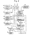
- Fig. 2 shows in block form a combinatorial computing apparatus.
- the n weight detectors. 12e the m weight detectors producing weight values W1-Wm are assumed to be associated with the weighing hoppers 12d of the rough charging weighing sections 12B, 12B, ..., and the (n-m) weight detectors producing weight values Wm+1, Wm+2, ... Wn are assumed to be associated with the weighing hoppers of the corrective charging weighing sections 12A, 12A, ....
- a gate 21 is opened in response to a signal from a control unit 22 to allow the weight values W1-Wm from the rough charging weight detectors 12e, 12e, ... to be delivered to an adder 23.
- the adder 23 computes the sum N1 of the supplied weight values, and issue such a sum N1 as a rough charging weight.
- a target weight setting and storing unit 25 sets and stores a target weight value X (g) which is supplied to a corrective charging weight generator 26.
- the corrective charging weight generator 26 is also supplied with the rough charging weight N1 and computes and issues a corrective charging weight TW which is the difference between the target weight X and the rough charging weight N1.
- a combinatorial computing unit 27, which employs a combination pattern supplied from a combination pattern generator 28 to select-and add some of the outputs Wm+1-Wm from the weight detectors 12e, 12e, ...
- the correktive charging weighing sections computes-a deviation or error between the total weight and the corrective charging weight TW, and compares the deviation or error with a stored content of an error memory (not shown) in the combinatorial computing unit 27. If the error is smaller than the stored data in the error memory, then the computed error is stored in the error memory and at the same time a gate 29 is opened to allow the combination pattern being generated by the combination pattern generator 28 to be stored in an optimum combination memory 30.
- Initial data stored in the error memory is equal to an upper limit of a preset allowable weight range.
- the combination pattern generator 28 comprises an(n-m)-bit counter for counting (2 n-m- 1) clock pulses (not shown) to generate 2("-m)- combination patterns.
- the bits of the (n-m)-bit counter correspond respectively to the corrective charging weighing sections. When the ith bit of the combination patterns is "1", the output from the weight detector belonging to the ith corrective charging weighing section is delivered to the combinatorial computing unit 27.
- the weights W6, W7, and W14from the first, second, and ninth weight detectors of'the corrective charging weighing section are delivered to the combination computing unit 27.
- the combination computing unit 27 effects the computation of an error between the sum of added weights and the corrective charging weight, the comparison between the error and the stored data in the error memory, and the renewal of the error memory and the optimum combination memory 30.
- a drive control unit 31 opens the weighing hopper gates 12f, 12f, ... of the weighing hoppers 12d, 12d, ... which give the optimum weight combination to discharge corrective charging articles into the chute 13.
- the main supply unit 11 supplies articles into the dispersion supply units 12a, 12a, ... in dependence upon how many articles have been discharged by the weighing apparatus, and the pool hoppers 12b, 12b, ..., and the weighing hoppers 12d, 12d, ... contain small numbers of articles, which are weighed by the weight detectors 12e, 12e, ....
- the control unit 22 issues a signal to the gate 21 to open the latter, whereupon the adder 23 computes the sum N1 of the weights Wl-W5 of the articles contained in the weighing hoppers assigned to the rough charging weighing sections, and delivers the computed sum N1 to the corrective weight generator 26 as a rough charging weight. Then, the control unit 22 applies an opening command to the drive control unit 31 to open the weighing hopper gates 12f, 12f, ... of the rough charging weighing hoppers. The weighing hopper gates 12f, 12f, ... of the rough charging weighing hoppers are opened for a certain period of time to discharge articles from all of the rough charging weighing hoppers into the timing hopper 14, via the chute 13.
- control unit 22 In response to a discharge-permit signal from a packing machine 32, the control unit 22 issues a discharge signal to the drive control unit 31 to open the timing hopper 14 to thereby discharge the rough charging articles from the timing hopper 14 into the container B1 positioned directly there below.
- the corrective weight generator 26 effects the arithmetic operation: to find the corrective charging weight TW and furnishes the latter to the combinatorial computing unit 27. Thereafter, the control unit 22 commands the combination pattern generator 28 to start generating combination patterns.
- the combinatorial computing unit 27 effects combinatorial computations to select a combination of the corrective charging weighing sections 12A which hold a total combined weight closest to the corrective charging weight TW, and stores the selected combination in the memory 30. After the combinatorial computations have been finished, the combinatorial computing unit 27 applies an end signal to the control unit 22, which then issues a series of supply and discharge start signals to the drive control unit 31.
- the drive control unit 31 now opens the weighing hopper gates, and closes the pool hopper gates, of those weighing sections 12A, 12A,... which correspond to bits "1" in the optimum combination memory 30.
- the opened weighing hopper gates and pool hopper gates will be closed upon the elapse of an interval of time set by a timer.
- the drive control unit 31 also drives the dispersion supply units 12a.
- the control unit 22 In response to a signal indicative of the opening of the weighing hopper gates by the drive control unit 31, and upon the elapse of a given period of time, the control unit 22 waits for a discharge-permit signal from the packing machine 32, and issues a discharge command to the drive control unit 31 upon receipt of such a discharge-permit signal and also a signal indicative of an article discharge to the packing machine 32.
- the drive control unit 31 responds to the discharge command by opening the timing hopper 14 to discharge the corrective charging articles into the container B1.
- the foregoing cycle of operation is repeated to produce successive quantities of articles which are each substantially equal in weight to the target weight X.
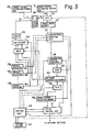
- Fig. 3 is a block diagram of a second combinatorial weighing apparatus (not embodying the present invention) in which a rough charging weight value is established separately from a target weight value. Identical parts in Fig. 3 are denbted by the same reference characters used in Fig. 2. In the first-mentioned apparatus, the weighing sections are divided into rough and corrective charging weighing sections. However, the weighing sections in the second weighing apparatus are not divided, but can be used for both rough and corrective charging operations.
- a rough charge setting and storing unit 51 serves to set and store a target for a weight measured for rough article charging (hereinafter referred to as a "target rough weight Wc").
- a gate 52 is responsive to a signal from a control unit 22 for inputting selectively the corrective weight TW generated from a corrective weight generator 26 or the target rough weight Wc stored in the rough charge setting and storing unit 51 into a target value memory 53.
- a combinatorial computing unit 27 effects combinatorial computations with the stored content of the target value memory 53 being used as a target value.
- a gate 21 opens under a command from the control unit 22 to transmit outputs from the weight detectors 12e, 12e, ... to a multiplexer 54.
- the multiplexer 54 is responsive to stored data in an optimum combination memory 30 for successively delivering the outputs from the weight detectors 12e of the weighing sections corresponding to bits "1" in the memory 30 to an adder 23.
- a rough charge selection memory 55 serves to take in and store the data from the optimum combination memory 30 when a gate 56 is opened.
- the weighing sections which are actuated by a drive control unit 31 to discharge articles are indicated by the rough charge selection memory 55 and the optimum combination memory 30.
- the rough charge selection memory 55 contains the result of a rough charging weighing operation, while the optimum combination memory 30 contains the result of a corrective charging weighing operation.
- the main supply unit 11 (Fig. 1) supplies articles to the dispersion supply units 12a, 12a, ... in dependence upon how many articles have been discharged by the weighing apparatus, and the pool hoppers 12b, 12b, ..., and the weighing hoppers 12d, 12d, ... contain small numbers of articles, which are weighed by the weight detectors 12e, 12e, ....
- the control unit 22 controls the gate 52 to allow the target rough weight Wc, stored in the rough charge setting and storing unit 51, to be stored in the target value memory 53, and enables the combination pattern generator 28 to start generating combination patterns.
- Combinatorial computations are effected by the combinatorial computing unit 27 with the stored data Wc in the target value memory 53 serving as a target weight.
- the optimum combination memory 30 stores a weight combination having bits "1" corresponding to the selected weighing sections.
- the control unit 22 issues an opening command to the gate 21.
- the multiplexer 54 successively delivers the weight data (W1, W1, ... Wn) from the weighing sections corresponding to bits "1" of the data stored at that time in the optimum combination memory 30 to the adder 23.
- the adder 23 computes the sum of the delivered weight data and issues the sum as a rough charging weight N1.
- the corrective charging weight generator 26 computes the difference (X-N1) between the target weight X and the rough charging weight N1, and issues the difference as a corrective charging weight TW through the gate 52 to the target value memory 53.
- the control unit 22 also responds to the combinatorial computation end signal by opening the gate 56 to allow transmission of the data from the optimum combination memory 30 to the rough charge selection memory 55. Thereafter, the control unit 22 issues a series of supply and dischage start signals to the drive control unit 31. The drive control unit 31 then discharges the rough charging articles held by the machines of the selected combination into the timing hopper 14, via the chute 13.
- control unit 22 waits for a discharge-permit signal from the packing machine 32 and then delivers a discharge signal to the drive control unit 31 in response to the discharge-permit signal.
- the drive control unit 31 responds to the discharge signal by opening the timing hopper 14 for a given interval of time to allow the rough charging articles to be discharged into the container B1 placed immediately therebelow.
- the control unit 22 commands the combination pattern generator 28 to start producing combination patterns.
- This beings combinatorial computations with the corrective charging weight TW used as a target weight.
- the combination pattern generator 28 takes in stored data from the rough charge selection memory 55 and generates combination patterns excluding those weighing sections corresponding to the bits "1" in the data from the memory 55. Combinatorial computations similar to those described above are carried out.
- the optimum combination memory 30 stores information having bits "1" corresponding to those weighing sections which are selected for corrective article charging.
- the control unit 22 commands the drive control unit 31 to start a series of supply and discharge operations.
- the control unit 22 issues a discharge signal to the drive control unit 31 in response to a discharge-permit signal from the packing machine 32. At this time, the control unit 22 also issues a discharge signal to the packing machine 32. In response to the discharge signal, the drive control unit 31 opens the timing hopper 14 to allow the corrective charging articles to be discharged into the container B1 in which the rough charging articles have already been charged. The foregoing cycle of operation is then repeated.
- combination patterns precluding those weighing sections already selected for rough charging are generated in combinatorial computations for corrective charging.
- the weight data from the weighing sections that have been selected for rough charging may instead be set as "0 g", and if any weighing sections selected for rough charging are contained in a finally selected combination pattern for corrective charging, such weighing sections may be inhibited.
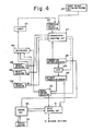
- Fig. 4 is a block diagram of a third combinatorial computing apparatus (not embodying the present invention). Identical parts in Fig. 4 are denoted by the same reference characters as those used in Figs. 2 and 3. Designated in Fig. 4 at 101 is a rough charge selector. According to the second-mentioned apparatus, the target rough charging weight is established, and rough charging weighing sections are selected through combinatorial computations. In the third weighing apparatus illustrated in Fig. 4, no combinatorial computations are performed, but another reference is utilized to select rough charging weighing sections. For example, such rough charging weighing sections may be selected sequentially in the order of their numbers to avoid their being selected overlappingly.
- a so-called multiple weighing operation is also possible in which all weighing sections are actuated to discharge articles for rough charging, then resupplied with articles before a combination of corrective charging weighing sections is selected from all of the weighing sections.
- a rough charging target value may be established, weights may be added successively in the order of their greater magnitudes, and the selection of rough charging weighing sections may be interrupted just before the rough charging target is exceeded.
- the apparatus of Fig. 4 is different from that of Fig. 3 only in that rough charging weighing sections are selected through the combinatorial computation or by another reference, and will operate in a similar manner. Therefore, detailed description of the operation of the apparatus shown in Fig. 4 will not be given here.
- a rough charging chute and a corrective charging chute are separately provided. Articles collected and discharged from the rough charging chute are charged into a container in a first position, and articles collected and discharged from the corrective charging chute are charged into the same container in a second position.
- the corrective charging chute serves to collect, into a lower central portion thereof, articles discharged from a plurality of weighing sections contained a combination of weighing sections 12A for corrective charging.
- the corrective charging chute 13 is of a conical funnel shape for colelcting, into the lower central portion thereof, those articles which have been discharged onto an outer peripheral edge by gravity or forcibly by a scraper (not shown).
- a timing hopper 14 serves to temporarily store the articles collected by the corrective charging chute 13, and discharge the stored articles into a container placed outside the weighing apparatus in response to a discharge signal generated from a packing machine or other external source.
- the rough charging chute designated at 15, serves to collect, into a lower central portion thereof, articles discharged from weighing sections 12B, for rough charging.
- the rough charging chute 15 is of a conical funnel shape for collecting, into the lower central portion, those articles which have been discharged onto an outer peripheral edge.
- a timing hopper 16 serves to temporarily store the articles collected by the rough charging chute 15, and discharge the stored articles into a container placed outside the weighing apparatus in response to a discharge signal generated from a packing machine or other external source.
- Containers B1, B2, B3,... are arranged in a rowto pass through a first point P1 where rough charging articles are discharged from the timing hopper 16 and a second point P2 where corrective charging articles are discharged from the timing hopper 14.
- a target weight is X (g)
- a rough charging process is carried out Z times successively without effecting a corrective charging process at an initial stage, and then the corrective and rough charging processes are performed in parallel relationship.
- the number of rough charging processes is regarded as being Z.
- Articles supplied from the main supply unit 11 are distributed and transported radially by the dispersion supply units 12a, 12a, ..., and then discharged into the pool hoppers 12b, 12b, .... Thereafter, the pool gates 12c, 12c, ... are opened to discharge the articles into the weighing hoppers 12d, 12d, .... Then; the dispersion supply units 12a, 12a, ... are driven and simultaneously the pool hopper gates 12c, 12c, ... are closed, whereupon articles are charged again into the pool hoppers 12b, 12b, .... When the apparatus has stopped vibrating after an interval of time set by a timer, the articles in the weighing hoppers 12d are weighed by the weight detectors 12e, 12e, ....
- the rough charging weight N1 of the article batch first discharged is taken out of the shift register, a corrective charging weight is computed which is the difference between a target weight X and the rough charging weight N1, and weighing machines which give a total combined weight equal or closest to the corrective charging weight are selected through a combinatorial computation from those weighing machines other than the m weighing sections for rough charging.
- a rough charging batch of articles is also found.
- the rough charging weighing hoppers 12d, 12d,... are opened simultaneously, or with a slight time delay, to allow articles for correcting charging to be collected into the timing hopper 14.
- the rough charging articles are collected through the rough charging chute 15 into the timing hopper 16.
- the rough charging weight N z+i of the (Z+1)th weighing process is stored in the shift register.
- the weighing hopper gates 12f, 12f, ... are closed, and at the same time prescribed pool hopper gates 12c, 12c, ... are opened to charge new articles from the pool hoppers 12b, 12, ... into the weighing hoppers 12d, 12d, ... from which the articles have been discharged.
- the pool hopper gates 12c, 12c, ... are closed and prescribed dispersion supply units 12a, 12a, ... are driven to supply new articles into the pool hoppers 12b, 12b, ... from which the articles have been discharged into the weighing hoppers 12d, 12d, ....
- the articles collected in the timing hoppers 14, 16 are discharged into containers outside the weighing apparatus in response to a signal supplied from the packing machine.
- the corrective charging articles having a total weight equal or closest to a corrective charging weight (X-N1) are discharged into the container B1, and hence articles having substantially the target weight X are now held in the container B1.
- One cycle ((Z+1)th) of weighing operation is now finished. Thereafter, the articles are weighed again, a rough charging weight N2 in the second weighing process is taken out of the shift register, a corrective charging weight (X-N2) is determined, and a combinatorial computation with the corrective charging weight as a target weight value is effected, a process which is repeated in the same manner as described above.
- the weighing cycle of the weighing apparatus and the charging cycle of the packing machine are in mutual synchronism.
- the container which contains rough charging articles discharged in Zth weighing process is located just below the timing hopper 14.
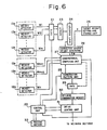
- Fig. 6 is a block diagram of a combinatorial computing apparatus.
- the n weight detectors .12e the m weight detectors producing weight values W1-Wm are assumed to be associated with the weighing hoppers 12d of the rough charging weighing sections 12B, 12B, ..., and the (n-m) weight detectors producing weight values Wm+1, Wm+2, ... Wn are assumed to be associated with the weighing hoppers of the corrective charging weighing sections 12A, 12A, ....
- a gate 21 is opened in response to a signal from a control unit 22 to allow the weight values W1-Wm from the rough charging weight detectors 12e, 12e, ... to be delivered to an adder 23.
- the adder 23 computes a sum N1 of the supplied weight values, and stores such a sum N1 at a most significant bit position in a shift register 24.
- the shift register 24 has a memory containing Z positions or more which are equal to the number of rough charging processes, one position being composed of several bits.
- the shift register serves to shift the data one position at a time, and issues the data from the least significant position.
- a target weight setting and storing unit 25 sets and stores a target weight value (X) (g) which is furnished to a corrective charging weight generator 26.
- the corrective charging weight generator 26 is also supplied with the rough charging weight measured in the Zth weighing process from the shift register 24 and computes and issues a corrective charging weight TW which is the difference between the target weight X and that rough charging weight.
- a combinatorial computing unit 27 is based on a combination pattern supplied from a combination pattern generator 28 for selecting and adding some of the outputs Wm+1-Wm from the weight detectors 12e, 12e, ...
- the corrective charging weighing sections for computing a deviation or error between the total weight and the corrective charging weight TW, and for comparing the deviation or error with a stored content of an error memory (not shown) in the combinatorial computing unit 27. If the error is smaller than the stored data in the error memory, then the computed error is stored in the error memory and at the same time a gate 29 is opened to allow the combination pattern being generated by the combination pattern generator 28 to be stored in an optimum combination memory 30.
- Initial data stored in the error memory is equal to an upper limit of a preset allowable weight range.
- the combination pattern generator 28 comprises an (n-m)-bit counter for counting (2n-m-1) clock pulses (not shown) to generate 2'" '"'-1 combination patterns.
- the bits of the (n-m)-bit counter correspond respectively to the corrective charging weighing sections.
- the weights W6, W7, and W14 from the first, second, and ninth weight detectors are delivered to the combination computing unit 27.
- the combination computing unit 27 effects the computation of an error between the sum of added weights and the corrective charging weight, the comparison between the error and the stored data in the error memory, and the renewal of the error memory and the optimum combination memory 30.
- a drive control unit 31 opens the weighing hopper gates 12f, 12f, ... of the weighing hoppers 12d, 12d, ... which give the optimum weight combination to discharge corrective charging articles into the chute 13.
- the main supply unit 11 supplies articles into the dispersion supply units 12a, 12a, ... in dependence upon how many articles have been discharged by the weighing apparatus, and the pool hoppers 12b, 12b, ..., and the weighing hoppers 12d, 12d, ... contain small numbers of articles, which are weighed by the weight detectors 12e, 12e, ....
- the control unit 22 issues a signal to the gate 21 to open the latter, whereupon the adder 23 computes the sum N1 of the weights W1W5 of the articles contained in the weighing hoppers assigned to the rough charging weighing sections, and delivers the computed sum N1 to the shift register 24 as a rough charging weight. Then, the control unit 22 applies a series of supply and discharge commands to the drive control unit 31, the commands including those for opening the weighing hopper gates 12f, 12f, ... of the rough charging weighing hoppers.
- the control unit 22 issues a discharge signal to the drive control unit 31 to open the timing hopper 16 for discharging the rough charging articles into a container positioned directly therebelow. This is the discharge of articles as a result of the first rough charging weighing operation.
- the articles contained in the rough charging weighing hoppers 12d, 12d, ... are rendered stable, and the outputs from the weight detectors 12e, 12e are under normal condition.
- the contol signal issues again a signal for opening the gate 21 to effect a cycle of operation similar to the first cycle of weighing operation.
- the apparatus will operate from the fourth cycle on as follows:
- the control unit 22 commands the combination pattern generator 28 to start generating combination patterns.
- the combinatorial computing unit 27 operates, on the basis of the combination patterns to effect combinatorial computations for selecting a combination from corrective charging weighing sections which gives a weight combination closest to a corrective weight, such a combination being stored in the optimum combination memory 30.
- the combinatorial computing unit 27 delivers an end signal to the contol unit 22, which then issues an opening signal to the gate 21.
- the adder 23 computes the sum of the weight data (W1, W2, ..., W5), and enters the computed sum as a (Z+1)th rough weight into the most significant position in the shift register 24. Then, the control unit 22 issues a series of supply and discharge start signals to the drive control unit 31.
- the drive control unit 31 now opens the weighing hopper gates and closes the pool hopper gates of the weighing sections 12B, 12B, ... assigned for rough charging and those weighing sections 12A, 12A, ... which correspond to bits "1" in the optimum combination memory 30.
- the opened weighing hopper gates and pool hopper gates will be closed upon the elapse of an interval of time set by a timer.
- the drive control unit 31 also drives the dispersion supply units.
- the control unit 22 In response to a signal indicative of the opening of the weighing hopper gates by the drive control unit 31 and upon the elapse of a given period of time, the control unit 22 waits for a discharge-permit signal from the packing machine 32, and issues a discharge command to the drive control unit 31 upon receipt of such a discharge-permit signal and also a signal indicative of an article discharge to the packing machine 32.
- the drive control unit 31 responds to the discharge command by opening the timing hoppers 14, 16 to discharge the rough charging and corrective charging articles.
- Fig. 7 shows a schematic view of the mechanism of a combinatorial weighing apparatus embodying the present invention.
- Identical parts shown in Fig. 7 are designated by the same reference characters used in Fig. 5.
- the combinatorial weighing apparatus shown in Fig. 7 is similar to the combinatorial weighing apparatus shown in Fig. 5.
- only one weighing hopper gate 12f, 12f, ... is associated with each weighing hopper 12d, 12d, ....
- two weighing hopper gates 12f, 12f, ... and 12f', 12f', ... are associated with each weighing hopper 12d, 12d, ....
- the weighing sections are divided into rough and corrective charging weighing sections, and no one weighing hopper is capable of discharging articles to both rough and corrective charging chutes.
- each weighing section in the weighing apparatus of Fig. 7 is not divided, but can be used for both rough and corrective charging operations.
- each weighing section is employed for rough charging of articles at one time and for corrective charging of articles at another time.
- one of the weighing hopper gates 12f' is opened to discharge articles into the rough charging chute 15.
- the other weighing hopper gate 12f is opened to discharge articles into the corrective charging chute 13.
- Fig. 8 is a block diagram of a first combinatorial computing apparatus for use with the apparatus of Fig. 7. Identical parts illustrated in Fig. 8 are designated by the same reference characters used in Fig. 6, and will not be described in detail.
- a rough charge setting and storing unit 51 serves to set and store a target for a weight measured for rough article charging (hereinafter referred to as a "target rough weight").
- a gate 52 responds to a signal from a control unit 22 by inputting the corrective weight TW generated by a corrective weight generator 26 or the target rough weight stored in the rough charge setting and storing unit 51 into a target value memory 53.
- a combinatorial computing unit 27 effects combinatorial computations with the stored content of the target value memory 53 being used as a target weight value.
- a gate 21 opens under a command from the control unit 22 to transmit outputs from the weight detectors 12e, 12e, ... to a multiplexer 54.
- the multiplexer 54 responds to stored data in an optimum combination memory 30 by successively delivering the outputs from the weight detectors 12e, 12e, ... of the weighing sections corresponding to bits "1" in the memory 30 to an adder 23.
- a selection memory 55 serves to take in and store the data from the optimum combination memory 30 when a gate 56 is opened.
- the weighing sections which are actuated by a drive control unit 31 to discharge articles are indicated by the selection memory 55 and the optimum combination memory 30.
- the selection memory 55 contains the result of a rough charging weighing operation, while the optimum combination memory 30 contains the result of a corrective charging weighing operation.
- the combinatorial weighing apparatus of Figs. 7 and 8 differs from that of Figs. 5 and 6 in that corrective charging combinatorial computations are performed to select corrective charging weighing sections from all weighing sections, and then rough charging combinatorial computations are performed to select rough charging weighing sections from the remaining weighing sections.
- the main supply unit 11 supplies articles into the dispersion supply units 12a, 12a, ... in dependence upon how many articles have been discharged by the weighing apparatus, and the pool hoppers 12b, 12b, ..., and the weighing hoppers 12d, 12d, ... contain small numbers of articles, which are weighed by the weight detectors 12e, 12e, ....
- the control unit 22 controls the gate 52 to allow the target rough charging weight stored in the rough charge setting and storing unit 51 to be stored in the target value memory 53, and enables the combination pattern generator 28 to start generating combination patterns.
- Combinatorial computations are effected by the combinatorial computing unit 27 with the stored data in the target value memory 53 serving as a target weight.
- the optimum combination memory 30 stores a weight combination having bits "1" corresponding to the selected weighing sections.
- the control unit 22 issues an opening command to the gate 21.
- the multiplexer 54 successively delivers the weight data (W1, W1,... Wn) from the weighing sections corresponding to bits "1" of the data stored in the optimum combination memory 30 to the adder 23.
- the adder 23 computes the sum of that weight data and enters the sum as a first rough charging weight into the shift register 24.
- the control unit 22 issues a series of supply and discharge start signals to the drive control unit 31.
- the drive control unit 31 then discharges the rough charging articles based on the optimum combination pattern, and performs other processes.
- Each of the weighing hoppers 12d, 12, ... is equipped with two weighing hopper gates 12f, 12f'.
- One of the hopper gates 12f' serves to discharge articles through the rough charging chute 15 into the timing hopper 16, and the other hopper gate 12f discharges articles via the corrective charging chute 13 into the timing hopper 14.
- the drive control unit 31 opens the weighing hopper gates 12f' leading to the rough charging chute 15 based on the stored data in the optimum combinatorial memory 30, and opens the weighing hopper gates 12f leading to the corrective charging chute 13 based on the stored data in the selection memory 55.
- the selection memory 55 is cleared, and the weighing hopper gates 12f' and the pool hopper gates 12b, 12b, ... are opened and the dispersion supply units 12a, 12a, ... are driven only for the weighing sections that have been selected for rough charging.
- the control unit 22 waits for a discharge-permit signal from the packing machine 32 and then delivers a discharge signal to the drive control unit 31 in reponse to the discharge-permit signal.
- the drive control unit 31 responds to the discharge signal by opening the timing hopper 16 for a given interval of time to discharge the rough charging articles into the container B1 placed immediately therebelow.
- the control unit 22 enables the gate 52 to transfer the corrective charging weight from the corrective charge weight generator 26 into the target value memory 53, and energizes the combination pattern 28 to start producing combination patterns. Then, combinatorial computations are carried out in which a target weight value is given by (the target weight X-the weight of rough charging articles discharged Z times before), to thereby select a combination from combinations of weight values (W1, W2, ... Wn) which gives a total weight equal or closest to the target corrective charging weight within an allowable range.
- the combinatorial computing unit 28 issues an end signal to the control unit 22.
- control unit 22 transfers the target rough charging weight value stored in the rough charge setting and storing unit 51 into the target value memory 53 through the gate 52, and at the same time issues an opening signal to the gate 56.
- the stored data in the rough charge setting and storing unit 51 enters the target value memory 53, and the stored data in the optimum combination memory 30 enters the selection memory 55.
- the control unit 22 commands the combination pattern generator 28 to start producing combination patterns.
- the combination pattern generator 28 takes in stored data from the selection memory 55 and generates combination patterns excluding those weighing sections corresponding to the bits "1" in the data from the memory 55. Combinatorial computations similar to those described above are carried out. When such combinatorial computations have been completed, the optimum combination memory 30 stores information having bits "1" corresponding to those weighing sections which are selected for rough article charging.
- the combinatorial computing unit 27 issues a command to open the gate 21.
- the multiplexer 54 successively delivers the weight data (W1, W2, ... Wn) corresponding to the bits "1" in the stored data in the optimum combination memory 30 to the adder 23, and the sum from the adder 23 is entered as the (Z+1)th rough charging weight value into the most significant position in the shift register 24.
- the control unit 22 commands the drive control unit 31 to start a series of supply and discharge operations.
- the control unit 22 issues a discharge signal to the drive control unit 31 in response to a discharge-permit signal from the packing machine 32.
- the control unit 22 also issues a discharge signal to the packing machine 32.
- the drive control unit 31 opens the timing hoppers.14,16 to allow the rough charging articles to be discharged into an empty container and the corrective charging articles to be discharged into the container in which the rough charging articles measured Z times before have already been charged. The foregoing cycle of operation is repeated thereafter.
- combination patterns precluding those weighing sections already selected for corrective charging are generated in combinatorial computations for rough charging.
- the weight data from the weighing sections that have been selected for corrective charging may be set as "0 g", and if any weighing sections selected for corrective charging are contained in a finally selected combination pattern for rough charging, such weighing sections may be inhibited.
- Fig. 9 is a block diagram of another combinatorial computing apparatus which may be used with the apparatus of Fig. 7. Identical parts in Fig. 9 are denoted by the same reference characters used in Figs. 6 and 8. Designated in Fig. 9 at 101 is a rough charge selector capable of selecting rough charging weighing sections from those precluding the weighing sections which give a weight combination closest to a corrective charging weight. According to the apparatus of Fig. 8, a target rough charging weight is established, and rough charging weighing sections are selected through combinatorial computations. According to the apparatus illustrated in Fig. 9, no combinatorial computations are performed but another reference is utilized to select rough charging weighing sections.
- all weighing sections left after corrective charging weighing sections have been selected may be utilized for rough charging, or rough charging weighing sections may be selected sequentially in the order of their numbers to avoid their being selected overlappingly.
- a so-called multiple weighing operation is also possible in which all weighing sections are actuated to discharge articles for rough charging, then re-supplied with articles, and a combination of corrective charging weighing sections is selected from all of the weighing sections.
- a rough charging target value may be established, weights may be added successively in the order of their greater magnitudes, and the selection of rough charging weighing sections may be interrupted just before the rough charging target is exceeded.
- articles can be discharged separately in two steps, so that large volume articles can be discharged with increased efficiency, and the likelihood that a bridge of articles will build up across a discharge port in the weighing apparatus can be reduced.
- Combinatorial weighing apparatus embodying the present invention differs from a single known combinatorial weighing apparatus in that it has a rough, and a corrective, charging chute, two weighing hopper gates attached to each weighing hopper, and a plurality of containers movable directly below both the chutes. Apparatus embodying the present invention, therefore, does not require any substantially greater space for installation than such known apparatus. In addition, with the apparatus of Fig. 8, since a combinatorial operation to select a corrective charging batch is performed using all the weighing machines, weighing accuracy can be improved.
- the total of weights of articles from all of the weighing sections is about 1.5 times a target weight value at the time of combinatorial computations for rough charging, and about (1 +a) times the target weight value when all of the remaining weighing sections are utilized for rough charging of articles after combinatorial computations have been carried out for corrective charging.
Landscapes
- Physics & Mathematics (AREA)
- General Physics & Mathematics (AREA)
- Weight Measurement For Supplying Or Discharging Of Specified Amounts Of Material (AREA)
Claims (4)
caractérisé par un moyen de transport pour déplacer un premier récipient (Bz) d'une position (P,) de chargement brut, à laquelle il reçoit une telle quantité initiale d'articles, à une position (P2) de chargement correctif pour recevoir les articles déchargés de ladite combinaison acceptable, et également caractérisé en ce que, après que ladite combinaison acceptable desdites machines (12) de pesage a été trouvée, une ou plusieurs autres machines de ladite pluralité sont employées à peser une seconde quantité initiale d'articles, qu'elles introduisent dans un second récipient (Bz+1) qui est alors déplacé, par le moyen de transport, de ladite position (Pi) chargement brut à ladite position (P2) de chargement correctif, les machines déchargées ayant été remplies sur ces entrefaites, et étant employées à la sélection d'une telle seconde combinaison acceptable des machines (12), en maintenant un poids combiné total d'articles égal ou le plus proche de la différence en poids entre ladite seconde quantité initiale d'articles et un poids cible sélectionné d'avance pour une seconde quantité désirée d'articles, aux fins de déchargement dans ledit second récipient (Bz+1), après quoi une ou plusieurs autres machines (12) de la pluralité sont employées à peser une troisième quantité initiale d'articles dans un troisième récipient (Bz+2) dans ladite position (P,) de chargement brut et ainsi de suite.
Applications Claiming Priority (4)
| Application Number | Priority Date | Filing Date | Title |
|---|---|---|---|
| JP10779182A JPS58223718A (ja) | 1982-06-23 | 1982-06-23 | 組み合せ計量装置 |
| JP107791/82 | 1982-06-23 | ||
| JP57234637A JPS59120821A (ja) | 1982-12-27 | 1982-12-27 | 組合せ計量装置 |
| JP234637/82 | 1982-12-27 |
Publications (3)
| Publication Number | Publication Date |
|---|---|
| EP0097532A2 EP0097532A2 (fr) | 1984-01-04 |
| EP0097532A3 EP0097532A3 (en) | 1985-08-07 |
| EP0097532B1 true EP0097532B1 (fr) | 1989-08-23 |
Family
ID=26447784
Family Applications (1)
| Application Number | Title | Priority Date | Filing Date |
|---|---|---|---|
| EP83303579A Expired EP0097532B1 (fr) | 1982-06-23 | 1983-06-21 | Dispositif de pesage combinatoire |
Country Status (4)
| Country | Link |
|---|---|
| US (1) | US4494619A (fr) |
| EP (1) | EP0097532B1 (fr) |
| AU (1) | AU544807B2 (fr) |
| DE (1) | DE3380448D1 (fr) |
Families Citing this family (24)
| Publication number | Priority date | Publication date | Assignee | Title |
|---|---|---|---|---|
| GB2137365A (en) * | 1983-03-29 | 1984-10-03 | David William Openshaw | Portion weighing apparatus |
| GB2147111B (en) * | 1983-09-28 | 1987-08-05 | Yamato Scale Co Ltd | Combination weighing with volumetric metering |
| JPS60134128U (ja) * | 1984-02-16 | 1985-09-06 | 株式会社 石田衡器製作所 | 計量装置 |
| AU572680B2 (en) * | 1984-08-09 | 1988-05-12 | Ishida Scales Mfg. Co. Ltd. | Weighing machine |
| US4711345A (en) * | 1984-08-28 | 1987-12-08 | Ishida Scales Mfg. Co., Ltd. | Composite-motion drive unit and combinatorial weighing apparatus employing the same |
| EP0282743A3 (fr) * | 1984-10-26 | 1990-05-16 | Ishida Scales Mfg. Co., Ltd. | Unité de contrôle pour un sytème de pesage combinatoire |
| GB2170013B (en) * | 1985-01-21 | 1988-05-25 | Yamato Scale Co Ltd | Combination weighing machines |
| US4676325A (en) * | 1985-05-10 | 1987-06-30 | Yamato Scale Company, Limited | Combination weighing method with two discharge paths and two target weights |
| JPH06105181B2 (ja) * | 1985-10-16 | 1994-12-21 | 株式会社川島製作所 | 組合せ秤量包装装置 |
| US4749008A (en) * | 1986-10-30 | 1988-06-07 | Kraft, Inc. | Methods and apparatus for container filling |
| US4705125A (en) * | 1986-11-14 | 1987-11-10 | Ishida Scales Manufacturing Company, Ltd. | Method of and apparatus for controlling hopper gate motion |
| US4905779A (en) * | 1987-06-01 | 1990-03-06 | Yamato Scale Company, Limited | Operation condition collator and methods |
| JP3509979B2 (ja) * | 1995-03-06 | 2004-03-22 | 大和製衡株式会社 | 定量充填装置 |
| DE69608925T2 (de) * | 1995-04-06 | 2001-01-04 | Yamato Scale Co. Ltd., Akashi | Vorrichtung zum Beladen eines Behälters mit abgewogenen Artikeln |
| US6493605B1 (en) * | 2000-08-24 | 2002-12-10 | General Mills, Inc. | Method and apparatus for distributing food product bits to a packager, especially gelatin-based product bits |
| DE60227803D1 (de) * | 2001-04-24 | 2008-09-04 | Skaginn Hf | Einbring-wägeverfahren und vorrichtung |
| WO2003008917A1 (fr) * | 2001-07-17 | 2003-01-30 | Marel Hf. | Procede et appareil permettant de mettre des articles en lot |
| EP1515125A1 (fr) * | 2003-09-11 | 2005-03-16 | Cabinplant International A/S | Dispositif et procédé de pesage et de mise en lot d'articles |
| US8735746B2 (en) * | 2010-01-11 | 2014-05-27 | Campbell Wrapper Corporation | Weighing apparatus and method |
| UA109920C2 (uk) | 2010-12-08 | 2015-10-26 | Байєр Кропсайєнс Елпі | Виробничі бази, способи і пристрій для обробки насіння |
| US9861027B2 (en) | 2010-12-08 | 2018-01-09 | Bayer Cropscience, Lp | Seed treatment systems and methods |
| US9959511B2 (en) | 2010-12-08 | 2018-05-01 | Bayer Cropscience Lp | Retail point seed treatment systems and methods |
| IL267981A (en) * | 2019-07-10 | 2021-01-31 | Ascher Ronen | A system for dividing non-uniform bulk material into portions |
| CN113670427A (zh) * | 2021-08-26 | 2021-11-19 | 深圳诺博医疗科技有限公司 | 称重自校正方法、处理模块、称重装置及存储介质 |
Family Cites Families (6)
| Publication number | Priority date | Publication date | Assignee | Title |
|---|---|---|---|---|
| GB1449481A (en) * | 1973-07-17 | 1976-09-15 | Hobart Eng Ltd | Weighing method and apparatus |
| US3945448A (en) * | 1974-07-18 | 1976-03-23 | Frito-Lay, Inc. | System for package weight control |
| IT1126209B (it) * | 1977-07-28 | 1986-05-14 | Mazzucchelli Ind Tessile | Apparecchiatura per eseguire la pesatura esatta di materiali di pezzatura variabile e specialmente di prodotti ortofrutticoli |
| US4313507A (en) * | 1978-03-09 | 1982-02-02 | Hays Gordon W | Weight portioning method and apparatus |
| US4399880A (en) * | 1981-01-27 | 1983-08-23 | Kabushiki Kaisha Ishida Koko Seisakusho | Combinatorial weighing system |
| US4341274A (en) * | 1981-04-06 | 1982-07-27 | Yamato Scale Company, Ltd. | Combination weighing device |
-
1983
- 1983-06-20 AU AU15928/83A patent/AU544807B2/en not_active Ceased
- 1983-06-21 EP EP83303579A patent/EP0097532B1/fr not_active Expired
- 1983-06-21 DE DE8383303579T patent/DE3380448D1/de not_active Expired
- 1983-06-22 US US06/506,797 patent/US4494619A/en not_active Expired - Lifetime
Also Published As
| Publication number | Publication date |
|---|---|
| EP0097532A3 (en) | 1985-08-07 |
| AU1592883A (en) | 1984-01-05 |
| US4494619A (en) | 1985-01-22 |
| EP0097532A2 (fr) | 1984-01-04 |
| AU544807B2 (en) | 1985-06-13 |
| DE3380448D1 (en) | 1989-09-28 |
Similar Documents
| Publication | Publication Date | Title |
|---|---|---|
| EP0097532B1 (fr) | Dispositif de pesage combinatoire | |
| EP0084968B1 (fr) | Méthode et dispositif de pesage | |
| EP0109844B1 (fr) | Peser d'un lot d'articles melangés | |
| EP0074260B1 (fr) | Dispositif de pesage combinatoire | |
| EP0071473B1 (fr) | Groupement combinatoire d'articles | |
| EP0063056B1 (fr) | Méthode de pesage combinatoire et appareil pour celui-ci | |
| EP0085446B1 (fr) | Méthode et dispositif pour le pesage en combination | |
| EP0060701B1 (fr) | Procédé et dispositif pour le réglage d'ajustement du point de zéro d'un détecteur du poids | |
| US4678046A (en) | Combination weighing apparatus for two combined products | |
| EP0261406A2 (fr) | Méthode de pesage combinatoire et appareil utilisant des bascules multi-bin | |
| EP0074261B1 (fr) | Dispositif de pesage combinatoire | |
| EP0079237A2 (fr) | Procédé de dosage employant des opérations de pesage combinatoire | |
| EP0076167B1 (fr) | Pesage ou comptage combinatoire d'articles | |
| EP0064554B1 (fr) | Procede et appareil de pesage par combinaison | |
| EP0103476A2 (fr) | Méthode de pesage combinatoire et dispositif y relatif | |
| EP0097530B1 (fr) | Dispositif de pesage combinatoire | |
| EP0105756B1 (fr) | Dispositif de pesage combinatoire et méthode | |
| JPH022090B2 (fr) | ||
| US4630695A (en) | Combinatorial weigher employing double group split logic | |
| EP0125080B1 (fr) | Méthode combinatoire de pesage et dispositif | |
| US4574897A (en) | Combinatorial weighing apparatus | |
| US4673046A (en) | Control system for combined weighing apparatus | |
| JPH0254886B2 (fr) | ||
| EP0097529B1 (fr) | Méthodes de pesage combinatoire et dispositif | |
| JPH0658246B2 (ja) | 組合せ計量装置 |
Legal Events
| Date | Code | Title | Description |
|---|---|---|---|
| PUAI | Public reference made under article 153(3) epc to a published international application that has entered the european phase |
Free format text: ORIGINAL CODE: 0009012 |
|
| AK | Designated contracting states |
Designated state(s): DE FR GB IT |
|
| PUAL | Search report despatched |
Free format text: ORIGINAL CODE: 0009013 |
|
| AK | Designated contracting states |
Designated state(s): DE FR GB IT |
|
| 17P | Request for examination filed |
Effective date: 19860107 |
|
| 17Q | First examination report despatched |
Effective date: 19870312 |
|
| GRAA | (expected) grant |
Free format text: ORIGINAL CODE: 0009210 |
|
| AK | Designated contracting states |
Kind code of ref document: B1 Designated state(s): DE FR GB IT |
|
| REF | Corresponds to: |
Ref document number: 3380448 Country of ref document: DE Date of ref document: 19890928 |
|
| ET | Fr: translation filed | ||
| ITF | It: translation for a ep patent filed | ||
| PLBE | No opposition filed within time limit |
Free format text: ORIGINAL CODE: 0009261 |
|
| STAA | Information on the status of an ep patent application or granted ep patent |
Free format text: STATUS: NO OPPOSITION FILED WITHIN TIME LIMIT |
|
| 26N | No opposition filed | ||
| ITTA | It: last paid annual fee | ||
| REG | Reference to a national code |
Ref country code: GB Ref legal event code: IF02 |
|
| PGFP | Annual fee paid to national office [announced via postgrant information from national office to epo] |
Ref country code: FR Payment date: 20020610 Year of fee payment: 20 |
|
| PGFP | Annual fee paid to national office [announced via postgrant information from national office to epo] |
Ref country code: GB Payment date: 20020619 Year of fee payment: 20 |
|
| PGFP | Annual fee paid to national office [announced via postgrant information from national office to epo] |
Ref country code: DE Payment date: 20020626 Year of fee payment: 20 |
|
| PG25 | Lapsed in a contracting state [announced via postgrant information from national office to epo] |
Ref country code: GB Free format text: LAPSE BECAUSE OF EXPIRATION OF PROTECTION Effective date: 20030620 |
|
| REG | Reference to a national code |
Ref country code: GB Ref legal event code: PE20 |