EP0097538A1 - System zur Verwaltung einer Objekt(Schlüssel)-Tafel - Google Patents
System zur Verwaltung einer Objekt(Schlüssel)-Tafel Download PDFInfo
- Publication number
- EP0097538A1 EP0097538A1 EP83400782A EP83400782A EP0097538A1 EP 0097538 A1 EP0097538 A1 EP 0097538A1 EP 83400782 A EP83400782 A EP 83400782A EP 83400782 A EP83400782 A EP 83400782A EP 0097538 A1 EP0097538 A1 EP 0097538A1
- Authority
- EP
- European Patent Office
- Prior art keywords
- objects
- key
- panel
- signaling
- location
- Prior art date
- Legal status (The legal status is an assumption and is not a legal conclusion. Google has not performed a legal analysis and makes no representation as to the accuracy of the status listed.)
- Granted
Links
Images

Classifications
-
- G—PHYSICS
- G07—CHECKING-DEVICES
- G07C—TIME OR ATTENDANCE REGISTERS; REGISTERING OR INDICATING THE WORKING OF MACHINES; GENERATING RANDOM NUMBERS; VOTING OR LOTTERY APPARATUS; ARRANGEMENTS, SYSTEMS OR APPARATUS FOR CHECKING NOT PROVIDED FOR ELSEWHERE
- G07C9/00—Individual registration on entry or exit
- G07C9/00174—Electronically operated locks; Circuits therefor; Nonmechanical keys therefor, e.g. passive or active electrical keys or other data carriers without mechanical keys
- G07C9/00896—Electronically operated locks; Circuits therefor; Nonmechanical keys therefor, e.g. passive or active electrical keys or other data carriers without mechanical keys specially adapted for particular uses
-
- A—HUMAN NECESSITIES
- A47—FURNITURE; DOMESTIC ARTICLES OR APPLIANCES; COFFEE MILLS; SPICE MILLS; SUCTION CLEANERS IN GENERAL
- A47G—HOUSEHOLD OR TABLE EQUIPMENT
- A47G29/00—Supports, holders, or containers for household use, not provided for in groups A47G1/00-A47G27/00 or A47G33/00
- A47G29/10—Key holders; Key boards
-
- G—PHYSICS
- G08—SIGNALLING
- G08B—SIGNALLING SYSTEMS, e.g. PERSONAL CALLING SYSTEMS; ORDER TELEGRAPHS; ALARM SYSTEMS
- G08B5/00—Visible signalling systems, e.g. visible personal calling systems or remote indication of seats occupied
- G08B5/22—Visible signalling systems, e.g. visible personal calling systems or remote indication of seats occupied using electric transmission; using electromagnetic transmission
- G08B5/36—Visible signalling systems, e.g. visible personal calling systems or remote indication of seats occupied using electric transmission; using electromagnetic transmission using visible light sources
-
- G—PHYSICS
- G07—CHECKING-DEVICES
- G07C—TIME OR ATTENDANCE REGISTERS; REGISTERING OR INDICATING THE WORKING OF MACHINES; GENERATING RANDOM NUMBERS; VOTING OR LOTTERY APPARATUS; ARRANGEMENTS, SYSTEMS OR APPARATUS FOR CHECKING NOT PROVIDED FOR ELSEWHERE
- G07C9/00—Individual registration on entry or exit
- G07C9/00174—Electronically operated locks; Circuits therefor; Nonmechanical keys therefor, e.g. passive or active electrical keys or other data carriers without mechanical keys
- G07C9/00896—Electronically operated locks; Circuits therefor; Nonmechanical keys therefor, e.g. passive or active electrical keys or other data carriers without mechanical keys specially adapted for particular uses
- G07C2009/00936—Electronically operated locks; Circuits therefor; Nonmechanical keys therefor, e.g. passive or active electrical keys or other data carriers without mechanical keys specially adapted for particular uses for key cabinets
Definitions
- the present invention relates to a system for managing a panel of objects such as keys.
- each nail is replaced by an opening through which the support is threaded to which a respective key is suspended.
- the gravity wedging of the support in the he opening activates a blade contact through a permanent magnet rod fixed to the support, and consequently excites a lamp indicating the storage of the key in the panel.
- the patent US Pat. No. 3,908,800 describes a system for selecting articles which are to be distributed in boxes of a storage trolley.
- a computer and a memory are provided for reading sequences of data, such as the location of boxes, to excite its indicator lights to prompt the operator to take quantities of items determined in the boxes.
- the operator after removing items from a specific box, the operator must press a button index which indicates the location of the next box.
- the object of the present invention is to provide an object management system and a corresponding panel which make it possible in particular to check the presence or the abnormal absence of objects in the panel as and when each predetermined combination is formed. of objects, such as a bunch of keys to a tour.
- the constitution of a combination of objects is carried out continuously by successive automatic tracking inviting the attendant to remove or return the objects to their locations without any errors.
- the subject of the invention is a system for managing a panel of objects as defined in claim 1.
- signaling means such as light-emitting diodes on the front face of the panel at the locations of the objects, facilitate the visual identification of the objects to be removed or introduced successively and therefore avoid any errors in the constitution of the combinations of objects.
- the management system is organized around a microprocessor with conventional peripheral units such as a keyboard, which makes it possible to dissociate the operations of organization of the tours, for example carried out the day before the tours, and the constitution of the combinations of objects such as keyrings.
- the panel comprises at each location a receptacle whose opening has a profile similar to a predetermined part of the object; for a key, the receptacle is analogous to a dummy lock.
- the means for detecting the presence or. the absence of objects have their states. automatically checked after each normal removal of an object during the constitution of a combination of objects, or after each normal introduction of an object during the return of objects following tours in order to detect in particular if one or more objects were abnormally removed from the panel by the attendant.
- alarm means signal the operator responsible for the locations of abnormally removed objects.
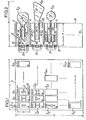
- the panel 1 is suitable for supporting MxN objects such as different keys 2 1.1 to 2 M, N.
- MxN is assumed to be 1000 in the following.
- the panel 1 essentially consists of a hollow parallelepiped base 10 the front face 11 of which is open and the bottom 12 of which is fixed against a wall or preferably in a locked safe.
- the base 10 presents MxN locations 3 1.1 to 3 M, N which are each assigned to a respective key 2 1.1 to 2 M, N.
- Each location 3 m, n where m varies between 1 and M and n varies between 1 and N, assigned to the respective key 2 is under m, n in the form of a parallelepipedal cell in which is housed a removable module.
- the bottom of a module 3 has two small tabs projecting towards the rear 30, in the form of flexible hooks opposite, which penetrate into a hole 13 in the bottom 12 of the panel in order to fix there by simple horizontal push the module 3 on the bottom 12.
- the modules can be separate individual elements, in particular in the case where the keys are all different but can constitute removable monobloc assemblies coming from molding each comprising for example one or more adjacent rows or columns of modules , in particular in the case where the keys for each monobloc assembly are identical.
- the width t, the height h and the depth p of a cell or module 3 are equal to 12mm, 27 mm and 46mm and the width L, the height H and the depth P of the base 10 are equal to 80cm, .60cm and 10 cm respectively.
- each key module or receptacle 3 is substantially coplanar with that 11 of the base 10 and has a central opening 31 whose profile is identical to the general section of a predetermined part such as the bit 20 of the key respective 2.
- the head 21 of the key 2 abuts against the front face of the module or else the end of the bit 20 of the key 2 abuts against the bottom of the module .
- the module is thus analogous to a dummy lock as shown in FIG. 2.
- Fig. 1 there are shown some profiles of openings 31 and key bits 20, such as in the shape of a rectangle, I, Y, cross, etc.
- each module 3 of a key 2 also includes a hole 32 in which is housed the end of a signaling means in the form of a light-emitting diode minescente 4 which lights up to invite the attendant to remove or introduce the key 2.
- each module 3 contains means 5 for detecting the key in order to signal the presence or absence of the respective key 2 of the module 3.
- Three embodiments of the key detection means are shown in FIG. 2.
- the first - above in Fig. 2 - is constituted by an opening contact 50 polarized by a diode. 51 in series.
- the end of one, 52, of the blades of the contact 50 is bent along a large radius of curvature against which slides the bit 20 of the key 2 during its introduction through the opening 31 which pushes the bent blade 52 against the other blade 53 in order to close the contact. 50.
- a spring such as another bent blade 54 is disposed symmetrically with the blade 52 and is applied against the other side of the bit 20 of the key in order to ensure guiding of the bit and consequently sufficient pressure of blade 52 against blade 53 of contact 50.
- the second embodiment of key detection means - in the second module from the top in FIG. 2- is constituted by a photocoupler whose radiating source 55 and the photosensitive receiver 56 are arranged on either side of the bit 20 of the key 2.
- the radiating source 55 can be a small lamp, a light emitting diode or photoemissive.
- the photosensitive receiver 56 can be a photodiode or a phototransistor.
- the radiating source 55 emits in the infrared in order to avoid any parasitic detection of visible light which can come in particular from the opening 31; in this case, the photosensitive receiver may be a charge coupled circuit element (CCD).
- CCD charge coupled circuit element
- the radiating source 55 is always supplied.
- the photosensitive receiver 56 is obscured when the key is inserted, or is activated and therefore produces a current which signals the absence of the key in the module.
- the sources. individual radiant sources 55 can be replaced by a single radiating source which is common to all the cells and placed for example on the bottom 12 of the base 10. The luminance of the common radiating source is relatively high so that its radiation can pass through holes suitable in the cells and modules and excite the photosensitive receptors opposite the holes.
- the third embodiment of key detection means - below in FIG. 2 - is an electromagnetic coupler.
- This coupler comprises a so-called transmitting coil 57 and a so-called receiving coil 58 which are arranged on either side of the bit 20 of the key. The axes of the coils are aligned perpendicular to the bit 20 of the key.
- the emitting coil 57 is continuously supplied.
- the receiving coil 58 no current flows when the key 2 is present in the module 3, and a current is induced by the magnetic flux emitted by the other coil 57 when the key 2 is absent from the module 3.
- the key detection means can comprise a polarized capacitor, the armatures of which are arranged on either side of the bit 20 of the key, for example at the locations of the aforementioned coils 57 and 58.
- the variation of the capacitor capacity indicates the presence or absence of the key in the module.
- the light-emitting diode 4 as well as the elements of the key detection means 5 of each module 3 are suitably fixed in the latter and have their terminals - four or six in number depending on the embodiment of the means 5 - in the form of pins 33 emerging from the bottom of the module and crossing the common bottom 12 of the cells of the panel 1 in order to carry out the wiring and the connection to the electronic management system of the panel.
- the management system is shown diagrammatically in FIG. 3 and is preferably integrated into a console in front of the panel.
- the management of the keys of the panel is organized around a microprocessor 60 which is connected according to a conventional diagram to a random access memory of data 61 of type (P) RAM and to a read-only memory of instructions 62 of type (P) ROM to through a bidirectional data and instruction bus 63 and a bidirectional address bus 64.
- the buses 63 and 64 are also connected to a parallel interface 65 which comprises a digital parallel-parallel converter, to a serial interface 66 which comprises a parallel-to-serial digital converter, and to a plurality of pairs of parallel interfaces 7L and 7C, one of which is illustrated in FIG. 3.
- the interface 65 serves a keyboard 67 with 16 keys as well as several signaling means 80, 81 and 82 which are arranged on the aforesaid console.
- the interface 66 is optionally provided for connecting the microprocessor 60 to other memories similar to memories 61 and 62 in order to adapt the capacity of all of the memories to the number of keys to be managed, and / or to a computer in view for example establishing statistical data on key management or having each round programmed by said computer.
- Each parallel interface 7L, 7C comprises eight elementary terminals numbered from 0 to 7 from top to bottom or from left to right in FIG. 3.
- the light-emitting diode 4 and the element 50-51, 56 or 58 of the key detection means 5 of the respective module are mounted head to tail between the respective terminals i and j.
- the diode 4 is directly polarized from terminal J to terminal I while contact 50-51 - or phototransistor 56 or take-up coil 58 - is biased directly from terminal I to terminal J.
- the light-emitting diode 4 in the module associated with the point 7 I, J is the only one excited to signal that the respective key must be removed or inserted when the terminal J is at the high level "1" and the other terminals of the interface of the columns 7C are at the low level “0” and when terminal I is at low level "0” and the other terminals of the interface of lines 7L are at level "1"; none of the polarized contacts 50 is excited whether the respective key is absent or present in the module.
- the contact 50 at the crossing point 7 I, J is conducting when the key is present in the module and connects the blades 52 and 53 which puts terminal J in state "0", which state will be read to verify that the key is present in the module; in the latter case, all the light-emitting diodes 4 are at rest and the contacts 50 at the other connection points do not induce any current even in the presence of their respective keys. From the above, it appears that the light-emitting diodes 4 of the matrix 8 ⁇ 8 can be excited individually and that the states of the contacts 50 or more generally of the key detection means 5 of the matrix can be read individually. The individual excitations and readings are sent by the microprocessor 60 via the bus 64 and the read state of a contact 50 is retransmitted to the microprocessor 60 via the bus 63.
- the microprocessor 60 delivers the address of this point as well as the addresses of the two respective interfaces 7L and 7C and a particular bit indicating that the diode 4 or the means 5 at the crossing point must be energized in order to apply the appropriate polarization.
- the number of the dispensing device and of the respective key of its box housing is given on the front face of the respective module 3 of the panel 1, as shown in FIG. 1.
- This number can. be engraved in an opaque plate placed in front of the respective light-emitting diode 4, which makes it easier to read the number by the tour attendant and the operator assigned to the desk.
- the operator composes on the keyboard 67 according to an appropriate code the data of the preceding table I, so that these are stored in the memory 61.
- the microprocessor will successively read the key numbers according to the predetermined order, it will deliver the addresses of the interfaces 7L and 7C and the number of the respective crossing point of the sub-matrix corresponding to each key number.
- the operator checks the presence of the keys in the panel by means of a program previously stored in memory 62 and called from the keyboard 67.
- the interface 7C When the interface 7C detects a terminal at an abnormal state "1", which indicates that the key is absent, the interface 7C delivers a coded word to the microprocessor 60. The latter verifies that this key should be absent, which is the case for the 24 crossing points not used for a panel with a thousand keys or for a crossing point whose key was removed normally during the formation of a bunch of keys of a tour as will be seen in the following.
- the microprocessor 60 delivers an alarm signal to the interface 65 which is converted, for example, into an audible alarm by a loudspeaker 80 placed on the console, and / or into a signal d reverse polarity at the two interfaces 7L and 7C so that the light-emitting diode 4 of the missing key module is activated.
- each agent Upon return of the agents having raised the boxes of the vending machines, each agent stores in the panel the keys to his round - in the same order or the reverse order chosen by the operator - following a program similar to that of withdrawal previously described .
- the microprocessor 60 assigns an address to each panel and each time a panel is used for the withdrawal or the introduction of one of its keys, a respective indicator light 82 is lit on the desk to orient the o operator to the sign in question.
- each of the essential constituent means of the management system or of the panel taken separately falls within the scope of the invention; this is particularly the case for the actual panel 1, the object module or receptacle 3, or one of the means 5 for detecting the presence or absence of an object.
Landscapes
- Physics & Mathematics (AREA)
- General Physics & Mathematics (AREA)
- Electromagnetism (AREA)
- Control Of Vending Devices And Auxiliary Devices For Vending Devices (AREA)
- Warehouses Or Storage Devices (AREA)
- Input From Keyboards Or The Like (AREA)
- Lock And Its Accessories (AREA)
Applications Claiming Priority (2)
| Application Number | Priority Date | Filing Date | Title |
|---|---|---|---|
| FR8208569A FR2526976B1 (fr) | 1982-05-17 | 1982-05-17 | Systeme de gestion d'un panneau d'objets tels que des cles |
| FR8208569 | 1982-05-17 |
Publications (2)
| Publication Number | Publication Date |
|---|---|
| EP0097538A1 true EP0097538A1 (de) | 1984-01-04 |
| EP0097538B1 EP0097538B1 (de) | 1986-07-30 |
Family
ID=9274107
Family Applications (1)
| Application Number | Title | Priority Date | Filing Date |
|---|---|---|---|
| EP83400782A Expired EP0097538B1 (de) | 1982-05-17 | 1983-04-20 | System zur Verwaltung einer Objekt(Schlüssel)-Tafel |
Country Status (6)
| Country | Link |
|---|---|
| US (1) | US4549170A (de) |
| EP (1) | EP0097538B1 (de) |
| DE (1) | DE3364879D1 (de) |
| DK (1) | DK215483A (de) |
| ES (1) | ES522118A0 (de) |
| FR (1) | FR2526976B1 (de) |
Cited By (3)
| Publication number | Priority date | Publication date | Assignee | Title |
|---|---|---|---|---|
| FR2583857A1 (fr) * | 1985-06-20 | 1986-12-26 | Salerno Claude | Installation de regulation de chauffage |
| FR2760557A1 (fr) * | 1997-03-05 | 1998-09-11 | Alcea | Armoire a cles pour equiper un systeme de controle d'acces, et procede et systeme de controle d'acces mettant en oeuvre cette armoire a cles |
| US6315198B1 (en) | 1997-03-05 | 2001-11-13 | Alcea | Key cabinet for equipping an access control system and access control method and system using this key cabinet |
Families Citing this family (41)
| Publication number | Priority date | Publication date | Assignee | Title |
|---|---|---|---|---|
| US4902626A (en) * | 1983-03-31 | 1990-02-20 | Kone Oy | Procedure and apparatus for assuring positive identification of samples for analysis |
| GB8323810D0 (en) * | 1983-09-06 | 1983-10-05 | Banks E J K | Supervising access to individual items |
| US4661806A (en) * | 1985-05-10 | 1987-04-28 | Peters Gilbert A | Computer controlled key management system |
| US4681504A (en) * | 1985-07-11 | 1987-07-21 | Welch Sr James A | Storage and inventory control system for keys |
| US4999611A (en) * | 1985-10-21 | 1991-03-12 | Zehnder Jr William | Towel cabinet replenishment indication and identification system |
| US4746907A (en) * | 1985-10-21 | 1988-05-24 | Zehnder Jr William | Towel cabinet replenishment indication and identification system |
| US4970508A (en) * | 1989-06-05 | 1990-11-13 | Webster Iii Daniel T | System for monitoring switch locations |
| US5038023A (en) * | 1989-06-28 | 1991-08-06 | C. Itoh Information Systems Development, Inc. | System for storing and monitoring bar coded articles such as keys in a drawer |
| DE4026287C2 (de) * | 1990-08-20 | 1994-02-17 | Rolf Dipl Ing Starec | Schlüsselkasten mit externer Zeilen- und Spaltenansteuerung matrixartig angeordneter Schlüsselpositionen zur Ausgabeautomatisierung |
| DE9104629U1 (de) * | 1991-04-16 | 1991-06-13 | Getronik elektronische Geräte GmbH, 3012 Langenhagen | Vorrichtung zur kontrollierten Ausgabe und Rückgabe von Schlüsseln aus Schließfachanlagen |
| US5205436A (en) * | 1991-11-06 | 1993-04-27 | Electronic Merchandising Systems, Inc. | Maine tool dispensing device and system |
| WO1995004324A1 (en) * | 1993-07-29 | 1995-02-09 | Morse Watchmans, Inc. | System and device for storing objects |
| JP2554312B2 (ja) * | 1994-06-10 | 1996-11-13 | 瑛 原 | ゴルフクラブ本数確認装置 |
| US6075441A (en) | 1996-09-05 | 2000-06-13 | Key-Trak, Inc. | Inventoriable-object control and tracking system |
| AU744133B2 (en) * | 1995-09-08 | 2002-02-14 | Key-Trak, Inc. | Inventoriable - object control and tracking system |
| ATE228679T1 (de) * | 1995-09-08 | 2002-12-15 | Key Trak Inc | Kontroll-und verfolgungssystem für inventarisierbare gegenstände |
| USD444331S1 (en) | 1996-09-05 | 2001-07-03 | Key-Trak, Inc. | Drawer panel |
| US6232876B1 (en) * | 1998-09-11 | 2001-05-15 | Key-Trak, Inc. | Mobile object tracking system |
| US6427913B1 (en) * | 1998-09-11 | 2002-08-06 | Key-Trak, Inc. | Object control and tracking system with zonal transition detection |
| WO2000016284A1 (en) | 1998-09-11 | 2000-03-23 | Key-Trak, Inc. | Tamper detection and prevention for an object control and tracking system |
| US6891473B2 (en) * | 1998-09-11 | 2005-05-10 | Key-Trak, Inc. | Object carriers and lighted tags for an object control and tracking system |
| CA2343411C (en) * | 1998-09-11 | 2002-11-12 | Key Control Holding, Inc. | Object carriers for an object control and tracking system |
| WO2000016280A1 (en) | 1998-09-11 | 2000-03-23 | Key-Trak, Inc. | Object tracking system with non-contact object detection and identification |
| SE517174C2 (sv) | 1999-09-15 | 2002-04-23 | Johnny Waerneloev | Sätt och anordning för identifikation och styrning av hantering av nycklar och dylikt |
| USD456852S1 (en) | 2000-03-31 | 2002-05-07 | Key-Trak, Inc. | Key tag |
| WO2002061654A1 (en) * | 2001-02-01 | 2002-08-08 | Key Register Systems, Inc. | Object storage and tracking system, an object tracking unit and a container for object tracking units |
| US7116228B1 (en) | 2001-02-20 | 2006-10-03 | Key Control Holding, Inc. | Asset management system |
| US6812838B1 (en) | 2001-04-26 | 2004-11-02 | Key-Trak, Inc. | Key control system using separate ID and location detection mechanisms |
| US6707381B1 (en) | 2001-06-26 | 2004-03-16 | Key-Trak, Inc. | Object tracking method and system with object identification and verification |
| US7336174B1 (en) | 2001-08-09 | 2008-02-26 | Key Control Holding, Inc. | Object tracking system with automated system control and user identification |
| EP1428330B1 (de) * | 2001-09-20 | 2005-05-25 | Honeywell, Inc. | Telefonsteuerung im einem flugdeck |
| US7623032B2 (en) * | 2002-12-05 | 2009-11-24 | Key Control Holding, Inc. | Object controlled access and inventory system |
| US7221274B2 (en) * | 2004-12-30 | 2007-05-22 | Alpha Security Products, Inc. | Docking station for security key |
| US20080087720A1 (en) * | 2006-10-11 | 2008-04-17 | Yevgeny Boris Levitov | Biometric Access Control System for Vending Machines |
| KR20090109281A (ko) * | 2008-04-15 | 2009-10-20 | 김기동 | 키 식별기능을 갖는 키 보관함 |
| US8191781B2 (en) * | 2008-12-23 | 2012-06-05 | Ncr Corporation | Method and apparatus for automated access control system |
| US8610574B2 (en) * | 2009-06-15 | 2013-12-17 | Gerald Isaac Kestenbaum | Item storage and tracking system |
| US9640014B2 (en) | 2011-01-04 | 2017-05-02 | Fawn Engineering Corporation | Vending machine with elevator delivery of vended product to customer access |
| US9870671B1 (en) | 2014-04-07 | 2018-01-16 | Fawn Engineering Corporation | Mechanical lift for delivery bins in vending machines |
| DE102014014431A1 (de) | 2014-09-29 | 2016-03-31 | automation & software Günther Tausch GmbH | Vorrichtung zur Einlagerung, Aufbewahrung und Ausgabe von aufhängbaren und/oder einhängbaren Schlüssel und/oder taschenförmigen Behältnissen |
| DE202014007890U1 (de) | 2014-09-29 | 2014-11-28 | automation & software Günther Tausch GmbH | Vorrichtung zur Einlagerung, Aufbewahrung und Ausgabe von aufhängbaren und/oder einhängbaren Schlüssel und/oder taschenförmigen Behältnissen |
Citations (3)
| Publication number | Priority date | Publication date | Assignee | Title |
|---|---|---|---|---|
| DE2025873A1 (de) * | 1970-05-27 | 1971-12-02 | Hübsch, Gerhard, 6451 Bischofsheim | Schlüsselbrett |
| US3908800A (en) * | 1974-04-12 | 1975-09-30 | Scope Inc | Item selecting system |
| US4205328A (en) * | 1977-01-20 | 1980-05-27 | Motohiro Gotanda | Apparatus for controlling a power source for an electrical alarm or indicator |
Family Cites Families (3)
| Publication number | Priority date | Publication date | Assignee | Title |
|---|---|---|---|---|
| US3251049A (en) * | 1964-01-09 | 1966-05-10 | Master Specialties Company | Master warning indicator system |
| US4060795A (en) * | 1973-02-23 | 1977-11-29 | Hitachi, Ltd. | Scanning system |
| JPS544099A (en) * | 1977-06-13 | 1979-01-12 | Hochiki Co | Fire alarm monitor controller |
-
1982
- 1982-05-17 FR FR8208569A patent/FR2526976B1/fr not_active Expired
-
1983
- 1983-04-20 DE DE8383400782T patent/DE3364879D1/de not_active Expired
- 1983-04-20 EP EP83400782A patent/EP0097538B1/de not_active Expired
- 1983-05-05 ES ES522118A patent/ES522118A0/es active Granted
- 1983-05-10 US US06/493,380 patent/US4549170A/en not_active Expired - Fee Related
- 1983-05-13 DK DK215483A patent/DK215483A/da not_active Application Discontinuation
Patent Citations (3)
| Publication number | Priority date | Publication date | Assignee | Title |
|---|---|---|---|---|
| DE2025873A1 (de) * | 1970-05-27 | 1971-12-02 | Hübsch, Gerhard, 6451 Bischofsheim | Schlüsselbrett |
| US3908800A (en) * | 1974-04-12 | 1975-09-30 | Scope Inc | Item selecting system |
| US4205328A (en) * | 1977-01-20 | 1980-05-27 | Motohiro Gotanda | Apparatus for controlling a power source for an electrical alarm or indicator |
Non-Patent Citations (1)
| Title |
|---|
| IBM TECHNICAL DISCLOSURE BULLETIN, vol. 21, no. 1, juin 1978, page 299, New York, USA * |
Cited By (4)
| Publication number | Priority date | Publication date | Assignee | Title |
|---|---|---|---|---|
| FR2583857A1 (fr) * | 1985-06-20 | 1986-12-26 | Salerno Claude | Installation de regulation de chauffage |
| FR2760557A1 (fr) * | 1997-03-05 | 1998-09-11 | Alcea | Armoire a cles pour equiper un systeme de controle d'acces, et procede et systeme de controle d'acces mettant en oeuvre cette armoire a cles |
| WO1998039741A1 (fr) | 1997-03-05 | 1998-09-11 | Alcea | Armoire a cles pour equiper un systeme de controle d'acces, et procede et systeme de controle d'acces mettant en oeuvre cette armoire a cles |
| US6315198B1 (en) | 1997-03-05 | 2001-11-13 | Alcea | Key cabinet for equipping an access control system and access control method and system using this key cabinet |
Also Published As
| Publication number | Publication date |
|---|---|
| US4549170A (en) | 1985-10-22 |
| FR2526976B1 (fr) | 1987-03-20 |
| EP0097538B1 (de) | 1986-07-30 |
| ES8405534A1 (es) | 1984-05-16 |
| DK215483D0 (da) | 1983-05-13 |
| DE3364879D1 (en) | 1986-09-04 |
| FR2526976A1 (fr) | 1983-11-18 |
| ES522118A0 (es) | 1984-05-16 |
| DK215483A (da) | 1983-11-18 |
Similar Documents
| Publication | Publication Date | Title |
|---|---|---|
| EP0097538B1 (de) | System zur Verwaltung einer Objekt(Schlüssel)-Tafel | |
| EP0306362B1 (de) | System zum Erfassen und Bearbeiten von Daten für die Prüfung von Kraftfahrzeugen | |
| FR3072492B1 (fr) | Procede pour initialiser ou mettre a jour une base de donnees de realogramme pour un lineaire, en utilisant des signaux optiques emis par des etiquettes electroniques de gondole | |
| EP0237420A1 (de) | Vorrichtung zum Lesen und Verteilen von Karten, insbesondere von Spielkarten. | |
| FR2570534A1 (fr) | Module d'affichage alphanumerique | |
| EP4074220B1 (de) | Weinkeller-regale | |
| FR2562293A1 (fr) | Dispositif pour le stockage, la distribution et la restitution d'objets a usages repetes | |
| EP0494014B1 (de) | Erzeugung einer Liste von Gegenständen für die Beladung von Behältern | |
| FR2829270A3 (fr) | Distributeur automatique actionne par une carte a puce | |
| EP0041457B1 (de) | Ausgabeautomat, mit herausnehmbarer Geldkassette und Verwaltungseinrichtung für diese Kassetten | |
| EP2521104A1 (de) | Steuerungsverfahren eines Modulsystems zur Verteilung von Gasflaschen, das mit mindestens einem Ständergestell mit einer Vielzahl von Flaschenfächern und einer Steuerungskontaktklemme für jedes Ständergestell ausgestattet ist, die über eine Funkverbindung verbunden sind | |
| EP0236191B1 (de) | Auf Grossbetrieb ausgerichtete industrielle Lagervorrichtung und Stückgutverteilung | |
| EP1076314A1 (de) | Lineare Personenidentifizierungsvorrichtung | |
| EP0291614B1 (de) | Schlüsselaufbewahrung und -inventar | |
| FR2631721A1 (fr) | Systeme electronique pour la collecte de produits stockes sur des palettes sans utiliser des nomenclatures d'emplacements et de prelevements | |
| FR2701142A1 (fr) | Système d'identification de recherche et de signalisation d'objets. | |
| EP0233232A1 (de) | Vorrichtung zur verteilung und zum verkauf von biegsamen trägern. | |
| EP0053079A1 (de) | Kompakte Einrichtung zum Simulieren eines Bridgespiels | |
| FR2963543A1 (fr) | Dispositif automatique pour le stockage et la distribution de bouteilles de gaz | |
| DK177661B1 (en) | Storage system for handling packages | |
| FR2510784A1 (fr) | Machine recreative dite " machine a sous " | |
| CN109770425B (zh) | 一种取烟器 | |
| JP3049357B1 (ja) | カタログディスペンサ― | |
| JPH0519116Y2 (de) | ||
| EP4689578A1 (de) | Ewigem inventar auf basis eines modularen lagerraums mit fächern |
Legal Events
| Date | Code | Title | Description |
|---|---|---|---|
| PUAI | Public reference made under article 153(3) epc to a published international application that has entered the european phase |
Free format text: ORIGINAL CODE: 0009012 |
|
| AK | Designated contracting states |
Designated state(s): BE CH DE GB IT LI NL SE |
|
| 17P | Request for examination filed |
Effective date: 19840131 |
|
| GRAA | (expected) grant |
Free format text: ORIGINAL CODE: 0009210 |
|
| AK | Designated contracting states |
Kind code of ref document: B1 Designated state(s): BE CH DE GB IT LI NL SE |
|
| REF | Corresponds to: |
Ref document number: 3364879 Country of ref document: DE Date of ref document: 19860904 |
|
| ITF | It: translation for a ep patent filed | ||
| PGFP | Annual fee paid to national office [announced via postgrant information from national office to epo] |
Ref country code: NL Payment date: 19870430 Year of fee payment: 5 |
|
| PLBE | No opposition filed within time limit |
Free format text: ORIGINAL CODE: 0009261 |
|
| STAA | Information on the status of an ep patent application or granted ep patent |
Free format text: STATUS: NO OPPOSITION FILED WITHIN TIME LIMIT |
|
| 26N | No opposition filed | ||
| PG25 | Lapsed in a contracting state [announced via postgrant information from national office to epo] |
Ref country code: GB Effective date: 19880420 |
|
| PG25 | Lapsed in a contracting state [announced via postgrant information from national office to epo] |
Ref country code: SE Effective date: 19880421 |
|
| PG25 | Lapsed in a contracting state [announced via postgrant information from national office to epo] |
Ref country code: LI Effective date: 19880430 Ref country code: CH Effective date: 19880430 |
|
| BERE | Be: lapsed |
Owner name: DOUCET JOEL Effective date: 19880430 Owner name: SERRES BERNARD Effective date: 19880430 |
|
| PG25 | Lapsed in a contracting state [announced via postgrant information from national office to epo] |
Ref country code: NL Effective date: 19881101 |
|
| NLV4 | Nl: lapsed or anulled due to non-payment of the annual fee | ||
| GBPC | Gb: european patent ceased through non-payment of renewal fee | ||
| REG | Reference to a national code |
Ref country code: CH Ref legal event code: PL |
|
| PG25 | Lapsed in a contracting state [announced via postgrant information from national office to epo] |
Ref country code: DE Effective date: 19890103 |
|
| PG25 | Lapsed in a contracting state [announced via postgrant information from national office to epo] |
Ref country code: BE Effective date: 19890430 |
|
| EUG | Se: european patent has lapsed |
Ref document number: 83400782.5 Effective date: 19890726 |