EP0236191B1 - Auf Grossbetrieb ausgerichtete industrielle Lagervorrichtung und Stückgutverteilung - Google Patents
Auf Grossbetrieb ausgerichtete industrielle Lagervorrichtung und Stückgutverteilung Download PDFInfo
- Publication number
- EP0236191B1 EP0236191B1 EP19870400248 EP87400248A EP0236191B1 EP 0236191 B1 EP0236191 B1 EP 0236191B1 EP 19870400248 EP19870400248 EP 19870400248 EP 87400248 A EP87400248 A EP 87400248A EP 0236191 B1 EP0236191 B1 EP 0236191B1
- Authority
- EP
- European Patent Office
- Prior art keywords
- rack
- central station
- goods
- detector
- installation
- Prior art date
- Legal status (The legal status is an assumption and is not a legal conclusion. Google has not performed a legal analysis and makes no representation as to the accuracy of the status listed.)
- Expired
Links
- 238000003860 storage Methods 0.000 title claims description 25
- 238000009434 installation Methods 0.000 claims description 23
- 239000011159 matrix material Substances 0.000 claims description 20
- 230000015654 memory Effects 0.000 claims description 8
- 230000005484 gravity Effects 0.000 claims description 3
- 230000000694 effects Effects 0.000 claims description 2
- 230000005281 excited state Effects 0.000 claims description 2
- 239000000047 product Substances 0.000 description 24
- 230000004044 response Effects 0.000 description 10
- 238000010586 diagram Methods 0.000 description 9
- 238000009826 distribution Methods 0.000 description 9
- 230000005540 biological transmission Effects 0.000 description 6
- 238000012360 testing method Methods 0.000 description 6
- 239000011521 glass Substances 0.000 description 4
- 238000002360 preparation method Methods 0.000 description 4
- 238000012545 processing Methods 0.000 description 3
- 239000004593 Epoxy Substances 0.000 description 2
- 238000004891 communication Methods 0.000 description 2
- 239000004020 conductor Substances 0.000 description 2
- 230000005284 excitation Effects 0.000 description 2
- 230000006870 function Effects 0.000 description 2
- 210000000056 organ Anatomy 0.000 description 2
- 238000004806 packaging method and process Methods 0.000 description 2
- 230000007704 transition Effects 0.000 description 2
- 238000011144 upstream manufacturing Methods 0.000 description 2
- 229910001369 Brass Inorganic materials 0.000 description 1
- 241001639412 Verres Species 0.000 description 1
- 230000003213 activating effect Effects 0.000 description 1
- 239000010951 brass Substances 0.000 description 1
- 230000008859 change Effects 0.000 description 1
- 210000000078 claw Anatomy 0.000 description 1
- 239000002537 cosmetic Substances 0.000 description 1
- 238000000151 deposition Methods 0.000 description 1
- 238000009429 electrical wiring Methods 0.000 description 1
- 229940082150 encore Drugs 0.000 description 1
- 238000004519 manufacturing process Methods 0.000 description 1
- 238000000034 method Methods 0.000 description 1
- 238000005192 partition Methods 0.000 description 1
- 238000005096 rolling process Methods 0.000 description 1
- 230000011664 signaling Effects 0.000 description 1
- 239000000126 substance Substances 0.000 description 1
- 239000013589 supplement Substances 0.000 description 1
- 229920002994 synthetic fiber Polymers 0.000 description 1
- 230000009897 systematic effect Effects 0.000 description 1
- 239000004753 textile Substances 0.000 description 1
- 238000012546 transfer Methods 0.000 description 1
- 230000000007 visual effect Effects 0.000 description 1
Images



Classifications
-
- B—PERFORMING OPERATIONS; TRANSPORTING
- B65—CONVEYING; PACKING; STORING; HANDLING THIN OR FILAMENTARY MATERIAL
- B65G—TRANSPORT OR STORAGE DEVICES, e.g. CONVEYORS FOR LOADING OR TIPPING, SHOP CONVEYOR SYSTEMS OR PNEUMATIC TUBE CONVEYORS
- B65G1/00—Storing articles, individually or in orderly arrangement, in warehouses or magazines
- B65G1/02—Storage devices
- B65G1/04—Storage devices mechanical
- B65G1/137—Storage devices mechanical with arrangements or automatic control means for selecting which articles are to be removed
- B65G1/1371—Storage devices mechanical with arrangements or automatic control means for selecting which articles are to be removed with data records
-
- B—PERFORMING OPERATIONS; TRANSPORTING
- B65—CONVEYING; PACKING; STORING; HANDLING THIN OR FILAMENTARY MATERIAL
- B65G—TRANSPORT OR STORAGE DEVICES, e.g. CONVEYORS FOR LOADING OR TIPPING, SHOP CONVEYOR SYSTEMS OR PNEUMATIC TUBE CONVEYORS
- B65G2209/00—Indexing codes relating to order picking devices in General
- B65G2209/04—Indication location means
Definitions
- the invention relates to industrial installations for the storage and distribution of products, on a large scale.
- Such installations comprise, in a room, rows of storage means having a front face facing the operator's passage (distribution of the stored products) and a rear face allowing the replenishment of the stored products.
- the storage means themselves consist of an arrangement (most often two-dimensional) of dynamic storage racks. Each of these compartments has a path suitable for transporting packages in a line, from rear to front, in principle by rolling. It will be understood that each package contains a product, in predetermined quantity, in correspondence with the locker concerned.
- Installations of this kind are used for distribution stocks in stores and warehouses, stocks of production or packaging plants, or for distribution centers in very diverse fields: food, pharmaceutical, cosmetic, textile, electronic or electromechanical components, chemicals, publishing, mail order, in particular.
- a card is attached to a package, judiciously placed, when filling the lockers from the rear.
- this card is discovered by the preparer (of orders), it means that the stock is exhausted.
- This manual method leaves the whole problem of transmitting information to the right person, in order to obtain replenishment quickly enough so as not to be out of stock.
- the present invention aims to provide a solution to this problem.
- Another object of the invention is to provide a flexible device for use, that is to say allowing in a simple manner all the required settings, depending on the packages and products stored in each locker.
- the invention also aims to solve the aforementioned problem by using means which are simple and inexpensive, and at the same time capable of withstanding an industrial environment.
- the invention starts from an installation of the aforementioned type, that is to say comprising, in a room, rows of storage means having a front face facing a distribution passage for the stored products, and a rear face allowing replenishment of stored products; the storage means themselves consisting of an arrangement, in particular two-dimensional, of dynamic storage racks, each of which is presented as a corridor, which has a path suitable for transporting by gravity, from the rear to the front, in a file , packages each containing a predetermined quantity of a product, in correspondence with the locker concerned.
- such an installation comprises, in combination:
- a package absence detector adjustable in position on the said path, relative to the front of the locker to indicate that the product stock has reached an acceptable minimum
- each coding matrix comprises at least 16 x 8 wires, to monitor at least 128 lockers.
- each concentrator comprises a stabilized double supply, in direct current, at 24 volts and 5 volts.
- the concentrators are interconnected by two channels in current rods, one starting from the central station to interrogate the concentrators, the other starting from these to return the information from the excited detector to the central station
- each absence detector comprises a support which can be clipped onto a rail with an Omega profile, running parallel to the package path, provided with a microswitch associated with an adjustable lever carrying a projecting roller, in the absence of packages, under the effect of the elastic return of the microswitch, the contact of the latter being then closed, while the presence of a package keeps this microswitch in the open state.
- the indicator is directly clipped onto an electrical wiring duct, easily allowing connection to the concentrator.
- a floor PL carries several tubular structures ST1 and ST2, between which is formed a product distribution passage DP.
- the structure ST1 comprises dynamic compartments CSD10 to CSD12, each capable of delivering by their downstream end, on the DP side, respective packages P10 to P12.
- the upstream end of these compartments constitutes a replenishment passage RA1.
- the structure ST2 comprises dynamic storage racks CSD20 to CSD24, delivering respectively packages of products P20 to P24, and provided at the rear with another passage RA2.
- An OP operator can thus pick up parcels corresponding to a command in each locker de, and put them together in a cart, or better on raceways such as CR.
- the figure also shows a PR printer, and an electronic control unit AE.
- PR printer and an electronic control unit AE.
- These elements can be used in the context of "paperless order preparation", to limit the operator's actions to depositing parcels on one of the CR tracks, which is dedicated to it. Indeed, the electronic cabinet AE and the printer PR can then take charge of the preparation of all the written documents required during the preparation of orders.
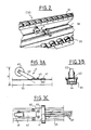
- Figure 2 shows better one of the dynamic storage racks CSD. This comprises, between partitions (possibly partial), not shown, a pair of raceways such as 31 and 32 (or groups of such raceways).
- a rail 33 which is preferably the omega rail standardized by electricians.
- a package absence detector 4 On this rail 33 is mounted a package absence detector 4, which will be described below in detail in FIGS. 3A to 3C.
- each dynamic rack is inclined, so that the packages move in file, by gravity, so that a package is always present on the side of the passage DP where the operator OP officiates.
- Each dynamic locker is associated with a package, that is to say with a packaging in determined quantity of a determined product. In other words, we can predict that the same product, packaged differently, will appear in several dynamic storage compartments.
- the absence detector of FIGS. 3A to 3C comprises, on the rail 33, a plate 40, which can be clipped by a claw 41 in any desired position on the rail 33.
- the plate 40 rotatably supports a lever 42, provided with its end of a roller 43, the upper edge of which is at a height H relative to the bottom of the rail 33.
- the plate 40 supports a microswitch 44, which is a waterproof IP65 protection microswitch, inverter , with a capacity of 5 amps under 220 volts, and which measures 23 x 20 x 9 mm.
- Screws 45 make it possible to adjust the microswitch 44 in position relative to the lever 42.
- the non-visible part of the latter abuts on the button of the microswitch 44, which thus provides the elastic return suitable for keeping the roller 43 in the high position.
- the screws 45 allow movement of the microswitch 44, and thereby the adjustment of the height position of the roller 43, the normal projection of which above the plane of the dynamic storage rollers is 8 mm, the height H being for its part adjustable between 40 and 55 mm. From the microswitch 44, inside the rail 33, three wires 49 go which go towards the upstream end of the dynamic storage rack CSD, that is to say on the side of the replenishment passage RA concerned.
- the position of the plate 40 is fixed for example at a point P4 ( Figure 1), which corresponds to the minimum allowable stock in this bin. This minimum is defined by the user taking into account the rate of output of the product, and the time necessary for its replenishment.
- the height of the roller, for its part, is adjusted according to the type of package and especially the support rails.
- FIG. 1 only one column of lockers has been shown in the structures ST1 and ST2. Of course, these also include horizontal rows of lockers such as CS10, which are not visible. Along each of these rows runs a chute, the position of which is illustrated in P5 in FIG. 1.
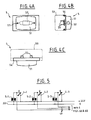
- This support chute which can be an electrical distribution chute of impact quality synthetic material, such as the GO 43 x 33 c model ( French standard PTT), is closed by its standard cover over its entire length, except at the middle of each dynamic storage locker. At this level, it carries a sight glass as illustrated in FIGS. 4A to 4B.
- the chute is here closed by the support 54 of the sight glass which clips onto it, and receives by screws 53 a diffuser 51, internally housing a shuttle lamp 52, while the latter is supplied by a pair of tinned brass lugs 6.3 x 0.8 mm double tab.
- the lamp holder is a laminate of epoxy glass 16 / 10th of a millimeter thick, while the lamp can be of the shuttle type 11 x 39, 3 watts, 24 volts.
- Figure 5 shows that, during the lifting of the roller 43 from one of the absence detectors 4-1 to 4-3, indicating the absence of a package at its level, a circuit is closed which operates the indicator corresponding, 5-1 to 5-3, respectively. Power is supplied at 24 volts DC.
- each of the detectors 4-1 to 4-3 is also connected to a respective device 6, which will be described below with reference to FIGS. 6A and 6B.
- FIG. 6A we find at 4 one of the absence detectors used according to the invention (although, in reality, the connection starts from the indicator, powered by the same detector).
- the direct voltage of 24 volts can directly attack the diode of the optocoupler, through a resistor 60 followed by a diode 61 mounted in reverse, allowing a limitation of the voltage at the terminals of the assembly located immediately downstream.
- This arrangement essentially comprises an optocoupler 65 whose light-emitting diode 66 is mounted between ground and the common point of the resistor 60 and the diode 61.
- the phototransistor 67 is mounted between a line L and a column C of a matrix 70 that we will describe now.
- the matrix 70 comprises eight lines L1 to L8, but which will also be noted DO to D7 to better understand their logic functions.
- the matrix also includes 16 columns, CO to C15 (or 0 to F, in hexadecimal).
- the eight wires of lines D0 to D7 are connected to a DC voltage of + 5 volts by resistors 71. Each of these resistors will thus be able to supply the collector of all the phototransistors 67 connected to this line.
- the emitters of the phototransistors are each time connected to the corresponding column wires.
- the matrix is provided with a connector 75, four pins of which control a decoder 72, which responds to the four input bits EA, EB, EC, ED by grounding those of columns CO to C15 whose number corresponds to the number defined by these four input bits.
- one of the absence detectors is excited, one of the phototransistors 67 is conductive, and consequently the corresponding line among DO to D7 will be found at a potential close to ground.
- phototransistors associated with the column being scanned are conductive, and several lines are simultaneously grounded.
- the multiplexer 73 interrogates the lines in sequence, in response to three bits SA, SB, SC coming from the connector 75.
- the information obtained is supplied on the output VS, to the connector 75.
- the device of FIGS. 6A and 6B can be constructed in a simple manner, by superposition on three levels, on the one hand of the matrix, on the other hand of an optocoupler plane 65, which can advantageously be a model with four outputs, of reduced format, such as the TLP 521-1 model from the company Toshiba, and finally on a third plane, the diodes 61 and resistors 60 with the 16 industrial 8-point connectors. This produces a compact cake, particularly suitable for the implementation of the invention.
- Figure 7 illustrates the block diagram of a concentrator, suitable for being connected to a matrix as illustrated in Figure 6B.
- Each concentrator comprises a microprocessor 80, connected by a bus 85 to the connector of each matrix 75, to memories 81, as well as to a double communication port 82 to which we will return later.
- the microprocessor can thus interrogate each locker, through the matrix which it controls, with the four bits EA to ED and the three bits SA to SC.
- EA to ED the four bits
- SA to SC the three bits
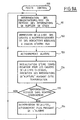
- FIG. 7A illustrates in the form of a flowchart the operation of such a concentrator, starting from an initial step 100.
- Step 101 consists in grounding column C0.
- Step 102 consists in examining lines 1 to 8. In the case where no alert is given or goes directly to step 103 which increments the column number grounded; step 104 checks whether or not the maximum has been reached. And if there are still columns to explore, we return to step 102.
- step 105 will then memorize the number of alerts encountered for the column number concerned and the number of line D of the absence detector having responded.
- step 110 determines whether the central station (described below) has requested information. If so, a branch 111 will transmit this information. (The transition to this branch can also be systematic, except of course for the transmission phase itself).
- a step 107 will record the stock shortage in memory, or a step 108 will on the contrary erase the corresponding information, stored in 103.
- the transmission 109 relates to the information confirmed at 107. After this transmission of information, or by the NO output of the test 110, we return to step 101.
- each concentrator will monitor sixteen times eight, or 128 dynamic storage lockers, and permanently determine those of these dynamic storage lockers whose stock they contain reaches the minimum admissible value. Note that at the same time, the indicator associated with each locker will be on.
- Figure 8 illustrates a loop interconnection current between a central PCI station, referenced 90, and different ports or communication interfaces 82-1, 82-2, etc., of hubs such as that of FIG. 7.
- interrogation current loop starting from the central station 90 to pass successively through the different concentrators, and transmitting to them the interrogation signal which is usually denoted RXD.
- This signal includes the interrogation order itself, accompanied by the address of the concentrator concerned, seen from the PCI central station.
- a BCR response current loop starts from the last concentrator, to go up these to 82-2, 82-1, to finally reach the central station 90.
- this loop response current can either transmit the TXD response signal from a previous hub, or that of the affected hub, as two hubs cannot respond at the same time.
- a housing 82 includes on the input of the interrogation current loop an optocoupler 130, whose output transistor has its emitter to ground and its connector connected on the one hand by a resistance to the usual VCC voltage, on the other hand by a reversing amplifier 131 at the input RXD of the local concentrator, and also by another reversing amplifier 132 following the current loop BCI towards the following concentrator, continuation of which the other wire is defined by a connection through a resistor 134 to the voltage VCC.
- an optocoupler 130 whose output transistor has its emitter to ground and its connector connected on the one hand by a resistance to the usual VCC voltage
- a reversing amplifier 131 at the input RXD of the local concentrator
- another reversing amplifier 132 following the current loop BCI towards the following concentrator, continuation of which the other wire is defined by a connection through a resistor 134 to the voltage VCC.
- the BCR current loop also attacks an optocoupler 140 whose output phototransistor has its emitter to ground and its collector connected by a resistor 141 to the VCC voltage, as well as by a reversing clipping amplifier 142 at an AND gate 143, the other input of which receives the TXD signal from the local concentrator.
- the output of the AND gate 143 is connected by an inverting amplifier 144 to one of the wires of the response current loop BCR which continues, while the other wire of the latter is defined by the connection of a resistance 145 at the VCC voltage.
- FIG. 9 describes the basic diagram of a central station 90, which comprises a central unit 91 associated with memories 92, with a printer 93, as well as with a siren 94.
- FIG. 9A illustrates the way in which this central station 90 works.
- a step 151 proceeds to the sequential interrogation of the concentrators, each time giving an RXD signal defined by the interrogation order and the address of the concentrator concerned.
- This same step consists in memorizing the stock-out information that the interrogated concentrator provides in response.
- a step 152 consists in printing the list of lockers to be replenished, and the indications associated with each of them.
- step 153 consists in actuating an audible and / or light alarm suitable for signaling to the personnel that it is necessary to restock.
- Step 154 then consists in initializing a time delay, defined taking into account the average replenishment time (in principle available in memory). During this delay, the alert information (the existence of an insufficient stock in the lockers concerned) is inhibited, until the end of the delay.
- Step 155 determines whether the timeout has elapsed for the lockers which have already been the subject of a list printing. If the delay has elapsed without replenishment having taken place, the list is printed again in step 156, and the alarm is actuated again, preferably more urgently.
- step 151 In the other output of test 155, or after operation 156, we return to step 151.
- FIG. 9A will only use the central PCI station in a limited way. This central station can naturally carry out many other interventions relating to the management of the stock of products.
- each concentrator verifies that the change of state of an absence detector is final by testing it for an adjustable period of 5 to 10 seconds.
- the delay observed by the central station before repeating the printing is of a much longer duration, of the order of at least half an hour.
Landscapes
- Engineering & Computer Science (AREA)
- Mechanical Engineering (AREA)
- Warehouses Or Storage Devices (AREA)
Claims (7)
Applications Claiming Priority (2)
| Application Number | Priority Date | Filing Date | Title |
|---|---|---|---|
| FR8601521 | 1986-02-04 | ||
| FR8601521A FR2593940B1 (fr) | 1986-02-04 | 1986-02-04 | Installation industrielle de stockage et de distribution de produits a grande echelle |
Publications (2)
| Publication Number | Publication Date |
|---|---|
| EP0236191A1 EP0236191A1 (de) | 1987-09-09 |
| EP0236191B1 true EP0236191B1 (de) | 1989-10-11 |
Family
ID=9331789
Family Applications (1)
| Application Number | Title | Priority Date | Filing Date |
|---|---|---|---|
| EP19870400248 Expired EP0236191B1 (de) | 1986-02-04 | 1987-02-03 | Auf Grossbetrieb ausgerichtete industrielle Lagervorrichtung und Stückgutverteilung |
Country Status (3)
| Country | Link |
|---|---|
| EP (1) | EP0236191B1 (de) |
| DE (1) | DE3760731D1 (de) |
| FR (1) | FR2593940B1 (de) |
Families Citing this family (5)
| Publication number | Priority date | Publication date | Assignee | Title |
|---|---|---|---|---|
| EP0282058B1 (de) * | 1987-03-11 | 1992-06-03 | Kao Corporation | Verfahren und Vorrichtung zum Zusammenstellen und Speichern von Waren |
| JPH04287290A (ja) * | 1990-11-20 | 1992-10-12 | Imra America Inc | ハフ変換画像処理装置 |
| CA2106098C (en) * | 1991-03-14 | 1996-07-02 | Shigeru Handa | Article control system |
| FR2678540B1 (fr) * | 1991-07-05 | 1997-01-17 | Eric Courtin | Procede et systeme d'aide a la distribution et au choix de pieces pour l'assemblage d'objets sur une chaine de montage industrielle. |
| WO2002079057A1 (en) * | 2001-03-15 | 2002-10-10 | Siemens Aktiengesellschaft | Controlled gravity accumulation conveyor |
Family Cites Families (4)
| Publication number | Priority date | Publication date | Assignee | Title |
|---|---|---|---|---|
| US2672289A (en) * | 1949-05-13 | 1954-03-16 | Punch Engineering Pty Ltd | Article dispensing system |
| FR1339922A (fr) * | 1962-11-23 | 1963-10-11 | Solartron Electronic Group | Dispositif de commande de distribution automatique |
| FR1515822A (fr) * | 1963-09-03 | 1968-03-08 | M E T O Soc D Applic Mecanique | Procédé et installation pour emmagasiner, prélever et comptabiliser des articles dans des containers de stockage |
| US4419734A (en) * | 1981-01-09 | 1983-12-06 | Indata Corporation | Inventory control system |
-
1986
- 1986-02-04 FR FR8601521A patent/FR2593940B1/fr not_active Expired
-
1987
- 1987-02-03 DE DE8787400248T patent/DE3760731D1/de not_active Expired
- 1987-02-03 EP EP19870400248 patent/EP0236191B1/de not_active Expired
Also Published As
| Publication number | Publication date |
|---|---|
| FR2593940A1 (fr) | 1987-08-07 |
| EP0236191A1 (de) | 1987-09-09 |
| DE3760731D1 (en) | 1989-11-16 |
| FR2593940B1 (fr) | 1988-07-15 |
Similar Documents
| Publication | Publication Date | Title |
|---|---|---|
| EP0097538B1 (de) | System zur Verwaltung einer Objekt(Schlüssel)-Tafel | |
| US9607465B2 (en) | Bulk vending apparatus, system and method | |
| EP0306362B1 (de) | System zum Erfassen und Bearbeiten von Daten für die Prüfung von Kraftfahrzeugen | |
| US8678232B2 (en) | Inventory storage and dispensing mechanism | |
| US8725290B2 (en) | Electronically controlled and monitored enclosure to dispense product packages | |
| CH640969A5 (fr) | Appareil d'enregistrement et de reproduction et cassette comportant une bande magnetique. | |
| EP0236191B1 (de) | Auf Grossbetrieb ausgerichtete industrielle Lagervorrichtung und Stückgutverteilung | |
| CN1170257C (zh) | 自动售货机的商品存放付出装置 | |
| FR2829270A3 (fr) | Distributeur automatique actionne par une carte a puce | |
| EP0543698B1 (de) | Vorrichtung zur Benutzung von Fehlerinformationen eines Einzel- oder Mehrrechnersystems eines Flugzeuges | |
| EP0041457B1 (de) | Ausgabeautomat, mit herausnehmbarer Geldkassette und Verwaltungseinrichtung für diese Kassetten | |
| EP0351335A1 (de) | Autonomer Ausgeber von Verlagsprodukten | |
| FR2557332A1 (fr) | Procede et appareil pour la deconsignation de bouteilles | |
| KR100454247B1 (ko) | 자동 판매기의 관리 시스템 및 그 방법 | |
| US20130152377A1 (en) | Method and apparatus for use in a vending machine | |
| CN1687973A (zh) | 一种自动售报机及专用装报袋 | |
| CN109770425B (zh) | 一种取烟器 | |
| EP4446962A1 (de) | Paketiersystem und -verfahren | |
| EP0949168B1 (de) | Pneumatische Rohrförderanlage zum Verteilen kleiner Packungen in grossen Warenhäusern | |
| WO1992015076A1 (fr) | Distributeur automatique d'articles conditionnes | |
| JP3781854B2 (ja) | 自動販売機の商品売切検出方法 | |
| FR2600193A1 (fr) | Dispositif d'affichage electronique de donnees | |
| JPH10312491A (ja) | 商品自動販売機 | |
| EP3023753A1 (de) | Verbesserte vorrichtung zum dosieren von flüssigkeiten, die aus einem behälter fliessen, und entsprechendes system | |
| JP2002150409A (ja) | 自動販売機の商品収納払出し装置 |
Legal Events
| Date | Code | Title | Description |
|---|---|---|---|
| PUAI | Public reference made under article 153(3) epc to a published international application that has entered the european phase |
Free format text: ORIGINAL CODE: 0009012 |
|
| AK | Designated contracting states |
Kind code of ref document: A1 Designated state(s): BE DE GB IT NL |
|
| 17P | Request for examination filed |
Effective date: 19871028 |
|
| 17Q | First examination report despatched |
Effective date: 19881219 |
|
| GRAA | (expected) grant |
Free format text: ORIGINAL CODE: 0009210 |
|
| AK | Designated contracting states |
Kind code of ref document: B1 Designated state(s): BE DE GB IT NL |
|
| REF | Corresponds to: |
Ref document number: 3760731 Country of ref document: DE Date of ref document: 19891116 |
|
| ITF | It: translation for a ep patent filed | ||
| GBT | Gb: translation of ep patent filed (gb section 77(6)(a)/1977) | ||
| PLBE | No opposition filed within time limit |
Free format text: ORIGINAL CODE: 0009261 |
|
| STAA | Information on the status of an ep patent application or granted ep patent |
Free format text: STATUS: NO OPPOSITION FILED WITHIN TIME LIMIT |
|
| 26N | No opposition filed | ||
| PGFP | Annual fee paid to national office [announced via postgrant information from national office to epo] |
Ref country code: GB Payment date: 19910220 Year of fee payment: 5 |
|
| PGFP | Annual fee paid to national office [announced via postgrant information from national office to epo] |
Ref country code: BE Payment date: 19910227 Year of fee payment: 5 |
|
| ITTA | It: last paid annual fee | ||
| PGFP | Annual fee paid to national office [announced via postgrant information from national office to epo] |
Ref country code: NL Payment date: 19910228 Year of fee payment: 5 |
|
| PGFP | Annual fee paid to national office [announced via postgrant information from national office to epo] |
Ref country code: DE Payment date: 19910326 Year of fee payment: 5 |
|
| PG25 | Lapsed in a contracting state [announced via postgrant information from national office to epo] |
Ref country code: GB Effective date: 19920203 |
|
| PG25 | Lapsed in a contracting state [announced via postgrant information from national office to epo] |
Ref country code: BE Effective date: 19920228 |
|
| BERE | Be: lapsed |
Owner name: SEBTY Effective date: 19920228 |
|
| PG25 | Lapsed in a contracting state [announced via postgrant information from national office to epo] |
Ref country code: NL Effective date: 19920901 |
|
| GBPC | Gb: european patent ceased through non-payment of renewal fee | ||
| NLV4 | Nl: lapsed or anulled due to non-payment of the annual fee | ||
| PG25 | Lapsed in a contracting state [announced via postgrant information from national office to epo] |
Ref country code: DE Effective date: 19921103 |
|
| PG25 | Lapsed in a contracting state [announced via postgrant information from national office to epo] |
Ref country code: IT Free format text: LAPSE BECAUSE OF NON-PAYMENT OF DUE FEES;WARNING: LAPSES OF ITALIAN PATENTS WITH EFFECTIVE DATE BEFORE 2007 MAY HAVE OCCURRED AT ANY TIME BEFORE 2007. THE CORRECT EFFECTIVE DATE MAY BE DIFFERENT FROM THE ONE RECORDED. Effective date: 20050203 |