EP0097594A2 - Clutch control system for a motor vehicle - Google Patents
Clutch control system for a motor vehicle Download PDFInfo
- Publication number
- EP0097594A2 EP0097594A2 EP83401274A EP83401274A EP0097594A2 EP 0097594 A2 EP0097594 A2 EP 0097594A2 EP 83401274 A EP83401274 A EP 83401274A EP 83401274 A EP83401274 A EP 83401274A EP 0097594 A2 EP0097594 A2 EP 0097594A2
- Authority
- EP
- European Patent Office
- Prior art keywords
- valve
- piston
- seat
- insert
- clutch
- Prior art date
- Legal status (The legal status is an assumption and is not a legal conclusion. Google has not performed a legal analysis and makes no representation as to the accuracy of the status listed.)
- Granted
Links
Images

Classifications
-
- F—MECHANICAL ENGINEERING; LIGHTING; HEATING; WEAPONS; BLASTING
- F16—ENGINEERING ELEMENTS AND UNITS; GENERAL MEASURES FOR PRODUCING AND MAINTAINING EFFECTIVE FUNCTIONING OF MACHINES OR INSTALLATIONS; THERMAL INSULATION IN GENERAL
- F16D—COUPLINGS FOR TRANSMITTING ROTATION; CLUTCHES; BRAKES
- F16D25/00—Fluid-actuated clutches
- F16D25/12—Details not specific to one of the before-mentioned types
- F16D25/126—Details not specific to one of the before-mentioned types adjustment for wear or play
-
- F—MECHANICAL ENGINEERING; LIGHTING; HEATING; WEAPONS; BLASTING
- F16—ENGINEERING ELEMENTS AND UNITS; GENERAL MEASURES FOR PRODUCING AND MAINTAINING EFFECTIVE FUNCTIONING OF MACHINES OR INSTALLATIONS; THERMAL INSULATION IN GENERAL
- F16D—COUPLINGS FOR TRANSMITTING ROTATION; CLUTCHES; BRAKES
- F16D25/00—Fluid-actuated clutches
- F16D25/08—Fluid-actuated clutches with fluid-actuated member not rotating with a clutching member
- F16D25/088—Fluid-actuated clutches with fluid-actuated member not rotating with a clutching member the line of action of the fluid-actuated members being distinctly separate from the axis of rotation
-
- F—MECHANICAL ENGINEERING; LIGHTING; HEATING; WEAPONS; BLASTING
- F16—ENGINEERING ELEMENTS AND UNITS; GENERAL MEASURES FOR PRODUCING AND MAINTAINING EFFECTIVE FUNCTIONING OF MACHINES OR INSTALLATIONS; THERMAL INSULATION IN GENERAL
- F16D—COUPLINGS FOR TRANSMITTING ROTATION; CLUTCHES; BRAKES
- F16D25/00—Fluid-actuated clutches
- F16D25/12—Details not specific to one of the before-mentioned types
- F16D25/14—Fluid pressure control
-
- F—MECHANICAL ENGINEERING; LIGHTING; HEATING; WEAPONS; BLASTING
- F16—ENGINEERING ELEMENTS AND UNITS; GENERAL MEASURES FOR PRODUCING AND MAINTAINING EFFECTIVE FUNCTIONING OF MACHINES OR INSTALLATIONS; THERMAL INSULATION IN GENERAL
- F16D—COUPLINGS FOR TRANSMITTING ROTATION; CLUTCHES; BRAKES
- F16D48/00—External control of clutches
- F16D48/02—Control by fluid pressure
- F16D48/04—Control by fluid pressure providing power assistance
- F16D2048/045—Vacuum boosters therefor
Definitions
- the present invention relates to a control system for the clutch of a motor vehicle.
- systems of this type which include a vacuum booster controlled by the accelerator pedal, in particular from French patent No. 2,056,958.
- This system includes a distribution valve whose drawer is controlled by the accelerator pedal, this valve comprising two outlet orifices both connected to one of the chambers of the booster, one of the connections comprising a valve controlled in accordance with the position of the actuator piston.
- the seat of this valve is adjusted in position so as to make the closed position of the valve coincide with the position of the clutch sliding. As the clutch wears down, the position of the valve seat must be modified accordingly to maintain this coincidence.
- valve seat is defined on an insert mounted frictionally in a guide, said insert being connected to the actuator piston by a unidirectional dead travel link.
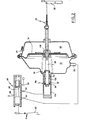
- the system shown schematically in Figure 1 comprises a servomotor 10 composed of a housing 12 in which is movably mounted a piston 11 which divides the housing into two chambers 16 and 18.
- the piston 14 is mechanically connected, for example by a connection to cable 20, to an input member 22 of the vehicle clutch (not shown).
- a return spring internal to the clutch recalls the member for entered in a rest position as shown in dotted lines in FIG. 1.
- the chamber 18 has an orifice 24 permanently open to the atmosphere, preferably via a filter 25.
- the chamber 16 has two orifices 26 and 28.
- a valve 30 controlled as a function of the position of the piston 14 and constituted essentially as follows: a valve seat 32 is defined in the vicinity of the orifice 26 on the side of the chamber 16, and a cover 34 is biased by a spring 36 in the direction of the seat 32, l operculum 34 carries a rod 38 which passes through the seat 32 and projects into the chamber 16 in the direction of the pirton 14.
- the valve 30 will be in the open or closed position. The rest of the structure of the valve 30 will be described in more detail later.
- the control system also includes a distribution valve 40 controlled by the accelerator pedal 42 of the vehicle.
- the valve 30 comprises a housing 44 provided with a bore 46 in which slides a drawer 48 returned by a spring 50 in contact with an extension 52 of the pedal 42.
- the drawer has two ranges 66 and 68 separated by a narrowing 70 which cooperate with the orifices 54, 58, 62 and 64 as will be seen below.
- the pedal 42 is returned to its rest position, as shown, by a spring 72 whose force is such that the slide 48 is moved against the spring 50 in a first position in which there has communication between the first inlet port 54 and the first outlet port 62 and where the other two orifices 58, 64 are blocked.
- the chamber 16 of the booster is placed in communication with the vacuum source 56 and the piston 14 is moved to the left if we consider the figure, by driving the input member 22 of the clutch into the position shown for which the clutch is released, and the driver of the vehicle can then make any gear change at l using the lever (not shown) provided for this purpose.
- the chamber 16 is placed in communication with the atmosphere and the piston 14 moves to the right, considering the figure, under the influence of the internal spring of the clutch.
- the chamber 16 is connected directly to the atmosphere via the orifice 28, and the piston 14 is then completely brought back to the right until in the rest position of the control member 22 of the clutch and which corresponds to its full commitment.
- valve seat 32 is defined on a sheath-shaped insert 102, mounted frictionally in a tubular guide 104 in the following manner: the sheath 102 has two peripheral grooves , the first housing a seal 108 and the second housing a rod 112 force-fitted into the tubular guide 104.
- a unidirectional dead-stroke link 116 At the opposite end 114 of the rod 38 which projects towards the piston 14 is provided a unidirectional dead-stroke link 116, in the following manner: the rod 38 has a projection 118 which extends through an orifice 120 in a cavity 122 of the piston 14 and the projection 118 comprises a flared head 124, of dimension greater than the orifice 120.
- a second valve seat 126 is defined on the insert 102 on the side of the chamber 16 and a second valve cap 128 is mounted on the rod 38 to define a second valve 130.
- the stroke of the piston Y corresponds to the free length of the projection 118 of the rod 38.
- the position of the insert 102 can be constantly and automatically adjusted so that the position of the piston 14 corresponding to the closing of the valve 30 coincides in all circumstances with the sliding position of the clutch.
- insert 102 When the clutch friction linings are replaced, insert 102 must be pushed towards the bottom of guide 104. This can be done simply by pushing piston 14 and rod 38 from the outside. thanks to mechanism 20.
- the insert will be automatically returned to the position corresponding to the sliding of the clutch.
Landscapes
- Engineering & Computer Science (AREA)
- General Engineering & Computer Science (AREA)
- Mechanical Engineering (AREA)
- Physics & Mathematics (AREA)
- Fluid Mechanics (AREA)
- Hydraulic Clutches, Magnetic Clutches, Fluid Clutches, And Fluid Joints (AREA)
Abstract
Description
La présente invention concerne un système de commande pour embrayage d'un véhicule automobile.The present invention relates to a control system for the clutch of a motor vehicle.
En particulier, on connait des systèmes de ce type qui comprennent un servomoteur à dépression commandé par la pédale d'accélérateur, notamment du brevet français No. 2 056 958.In particular, systems of this type are known which include a vacuum booster controlled by the accelerator pedal, in particular from French patent No. 2,056,958.
Un système analogue et notablement simplifié est décrit dans la demande de brevet déposé ce même jour au nom de Franco Ravasio pour un système de commande pour embrayage d'un véhicule automatique.A similar and significantly simplified system is described in the patent application filed that same day in the name of Franco Ravasio for a control system for clutching an automatic vehicle.
Ce système comprend une valve de distribution dont le tiroir est commandé par la pédale d'accélérateur, cette valve comportant deux orifices de sortie reliés tous deux à l'une des chambres du servomoteur, l'une des liaisons comportant un clapet commandé en fonction de la position du piston du servomoteur.This system includes a distribution valve whose drawer is controlled by the accelerator pedal, this valve comprising two outlet orifices both connected to one of the chambers of the booster, one of the connections comprising a valve controlled in accordance with the position of the actuator piston.
Comme indiqué dans ce document, le siège de ce clapet est réglage en position de manière à faire coïncider la position de fermeture du clapet avec la position du glissement de l'embrayage. Au fur et à mesure de l'usure de l'embrayage, il y a lieu de modifier en conséquence la position du siège de clapet pour maintenir cette coïncidence.As indicated in this document, the seat of this valve is adjusted in position so as to make the closed position of the valve coincide with the position of the clutch sliding. As the clutch wears down, the position of the valve seat must be modified accordingly to maintain this coincidence.
Dans le but de supprimer cette intervention, selon la présente invention, le siège de clapet est défini sur un insert monté à friction dans un guide, ledit insert étant relié au piston de servomoteur par une liaison unidirectionnelle à course morte.In order to eliminate this intervention, according to the present invention, the valve seat is defined on an insert mounted frictionally in a guide, said insert being connected to the actuator piston by a unidirectional dead travel link.
Un mode de réalisation de l'invention sera maintenant décrit en se référant aux trois figures annexées, qui sont des représentations schématiques d'un système de commande pour embrayage d'un véhicule automobile, dans trois positions de fonctionnement différentes.An embodiment of the invention will now be described with reference to the three attached figures, which are schematic representations of a control system for the clutch of a motor vehicle, in three different operating positions.
Le système représente schématiquement à la figure 1 comprend un servomoteur 10 composé d'un boîtier 12 dans lequel est monté mobile un piston 11 qui divise le boîtier en deux chambres 16 et 18. Le piston 14 est relié mécaniquement, par exemple par une liaison à câble 20, à un organe d'entrée 22 de l'embrayage du véhicule (non représenté). De manière connue en soi, un ressort de rappel interne à l'embrayage rappelle l'organe d'entrée dans une position de repos telle que représentée en pointillé à la figure 1.The system shown schematically in Figure 1 comprises a
La chambre 18 comporte un orifice 24 ouvert en permanence à l'atmosphère de préférence via un filtre 25. La chambre 16 comporte deux orifices 26 et 28. Dans le premier de ces deux orifices 26 est monté un clapet 30 commandé en fonction de la position du piston 14 et constitué essentiellement de la manière suivante : un siège de clapet 32 est défini au voisinage de l'orifice 26 du côté de la chambre 16, et un opercule 34 est sollicité par um, ressort 36 en direction du siège 32, l'opercule 34 porte une tige 38 qui traverse le siège 32 et se projette dans la chambre 16 en direction du pirton 14. Ainsi, selon la position du piston 14 dans le boîtier 12, le clapet 30 sera en position ouverte ou fermée. Le reste de la structure du clapet 30 sera décrit plus en détail ultérieurement.The
Le système de commande comprend également une valve de distribution 40 commandée par la pédale d'accélérateur 42 du véhicule.The control system also includes a
La valve 30 comporte un boîtier 44 pourvu d'un alésage 46 dans lequel coulisse un tiroir 48 rappelé par un ressort 50 au contact d'une extension 52 de la pédale 42.The
Dans l'alésage 46 débouchent quatre orifices:
- - un premier orifice d'entrée 54 relié à une source de
dépression 56, constituée par exemple par le collecteur d'admission du moteur du véhicule; - - un second orifice d'entrée 58 relié à l'atmosphère, de préférence via un
filtre 60 ; - - un premier orifice de
sortie 62 relié auclapet 30 ; et - - un second orifice de
sortie 64 relié à l'orifice 28 duservomoteur 10.
- - A
first inlet port 54 connected to avacuum source 56, constituted for example by the vehicle engine intake manifold; - a
second inlet port 58 connected to the atmosphere, preferably via afilter 60; - - a
first outlet orifice 62 connected to thevalve 30; and - a
second outlet port 64 connected toport 28 of thebooster 10.
Le tiroir comporte deux portées 66 et 68 séparées par un rétrécissement 70 qui coopèrent avec les orifices 54, 58, 62 et 64 comme il sera vu ci-après.The drawer has two
Enfin, de manière classique la pédale 42 est rappelée dans sa position de repos, telle que représentée, par un ressort 72 dont la force est telle que le tiroir 48 est déplacé à l'encontre du ressort 50 dans une première position dans laquelle il y a communication entre le premier orifice d'entrée 54 et le premier orifice de sortie 62 et où les deux autres orifices 58, 64 sont bloqués.Finally, in a conventional manner, the
Dans cette situation, la chambre 16 du servomoteur est mise en communication avec la source de dépression 56 et le piston 14 est déplacé vers la gauche si l'on considère la figure, en entrainant l'organe d'entrée 22 de l'embrayage dans la position représentée pour laquelle se produit le débrayage, et le conducteur du véhicule peut alors effectuer tout changement de vitesse à l'aide du levier (non représenté) prévu à cet effet.In this situation, the
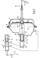
Lorsque le conducteur commence à appuyer sur la pédale d'accélérateur, en un premier temps le tiroir 48 se déplace vers la gauche jusqu'à occuper une seconde position pour laquelle le premier orifice d'entrée 54 est bloqué et il y a communication entre le second orifice d'entrée 5ti et le premier orifice de sortie 62, comme représenté à la figure 2.When the driver begins to press the accelerator pedal, firstly the
Dans cette situation, la chambre 16 est mise en communication avec l'atmosphère et le piston 14 se déplace vers la droite, en considérant la figure, sous l'influence du ressort interne de l'embrayage.In this situation, the
Lorsque le piston 14 a atteint une position prédéterminée, l'opercule 34 du clapet 30 vient au contact du siège 32 et la liaison entre la chambre 16 et l'atmosphère est interrompue. Le piston 14 demeure alors dans cette position. Comme il sera vu ci-après, cette position coïncide en toutes circonstances d'entrée 22 de l'embrayage pour laquelle se produit le glissement de l'embrayage.When the
En un second temps, lorsque le conducteur poursuit l'enfoncement de la pédale 42, le tiroir 48 se déplace à nouveau vers la gauche et vient occuper une troisième position dans laquelle le tiroir 48 établit une communication entre le second orifice d'entrée 58 et le second orifice de sortie 64, comme représenté à la figure 3.In a second step, when the driver continues to depress the
Dans cette situation, la chambre 16 est reliée directement à l'atmosphère via l'orifice 28, et le piston 14 est alors totalement ramené vers la droite jusque dans la position de repos de l'organe de commande 22 de l'embrayage et qui correspond à l'engagement complet de celui- ci.In this situation, the
Si l'on considère à nouveau la figure 1, on note que le siège de clapet 32 est défini sur un insert 102 en forme de fourreau, monté à friction dans un guide tubulaire 104 de la manière suivante : le fourreau 102 comporte deux gorges périphériques, la première abritant un joint d'étanchéité 108 et la seconde abritant un jonc 112 monté à force dans le guide tubulaire 104.If we again consider Figure 1, we note that the
A l'extrémité opposée 114 de la tige 38 qui se projette vers le piston 14 est prévu une liaison unidirectionnelle à course morte 116, de la manière suivante : la tige 38 comporte une projection 118 qui s'étend au travers d'un orifice 120 dans une cavité 122 du piston 14 et la projection 118 comporte une tete évasée 124, de dimension supérieure à l'orifice 120.At the
Enfin, un second siège de clapet 126 est défini sur l'insert 102 du coté de la chambre 16 et un second opercule de clapet 128 est monté sur la tige 38 pour définir un second clapet 130.Finally, a
Dans la situation illustrée à la figure 1, la mise sous dépression de la chambre 16 provoque le déplacement du piston 14 vers la gauche et le débrayage du véhicule ; cependant, le piston 14 est limité dans sa course parce que lorsque le second opercule 128 vient atteindre le siège 126, il y a fermeture de la liaison entre la chambre 16 et la source de dépression. On évite ainsi d'imprimer des efforts excessifs au mécanisme de liaison à l'organe d'entrée 22 de l'embrayage, grâce au clapet 130.In the situation illustrated in FIG. 1, placing the
Durant la première phase de l'enfoncement de la pédale d'accélérateur (Figure 2), l'air est introduit dans la chambre 16 via la valve 40 et le clapet 30 ; le piston 14 se déplace alors vers la droite, la tige 38 se déplaçant conjointement avec le piston.During the first phase of depressing the accelerator pedal (Figure 2), air is introduced into the
Après une course X, l'opercule 34 vient au contact du siège 32 et le piston 14 s'immobilise dans la position illustrée, l'organe 22 ayant alors atteint la position pour laquelle se produit le glissement de l'embrayage.After a race X, the
Durant la seconde phase de l'enfoncement de l'accélérateur (Figure 3), l'air est introduit directement dans la chambre 16 via la valve 40 et l'orifice 28. Le piston se déplace vers la droite jusque dans la position correspondant au plein engagement de l'embrayage.During the second phase of depressing the accelerator (Figure 3), air is introduced directly into
La course du piston Y correspond à la longueur libre de la projection 118 de la tige 38.The stroke of the piston Y corresponds to the free length of the
Au fur et à mesure de l'usure de l'embrayage, la position finale du piston 14 se déplace progressivement vers la droite de la figure. Il en est naturellement de même pour la position de glissement.As the clutch wears down, the final position of the
Grâce à l'invention, la position de l'insert 102 pourra être constamment et automatiquement ajustée pour que la position du piston 14 correspondant à la fermeture du clapet 30 coïncide en toutes circonstances avec la position de glissement de l'embrayage.Thanks to the invention, the position of the
En effet, lorsque la position finale du piston 14 se déplace vers la droite, le piston exerce une traction sur la tige 38 par l'intermédiaire de la tête 124 de sa projection 118, traction qui est transmise par l'opercule 34 à l'insert 102. Cette traction étant supérieure à la force de friction entre le jonc 114 et le guide 104, l'insert se déplace donc vers la droite pour atteindre une nouvelle position conforme à l'état d'usure de l'embrayage.In fact, when the final position of the
Lorsqu'on procède au remplacement des garnitures de friction de l'embrayage, il y a lieu de repousser l'insert 102 vers le fond du guide 104. Ceci peut se faire simplement en repoussant le piston 14 et la tige 38 de l'extérieur grâce au mécanisme 20.When the clutch friction linings are replaced,
Dès la première action sur la pédale 42, l'insert sera ramené automatiquement dans la position correspondant au glissement de l'embrayage.As of the first action on the
Claims (4)
Applications Claiming Priority (2)
| Application Number | Priority Date | Filing Date | Title |
|---|---|---|---|
| IT2195682 | 1982-06-21 | ||
| IT21956/82A IT1152257B (en) | 1982-06-21 | 1982-06-21 | CONTROL SYSTEM FOR THE CLUTCH OF A VEHICLE |
Publications (3)
| Publication Number | Publication Date |
|---|---|
| EP0097594A2 true EP0097594A2 (en) | 1984-01-04 |
| EP0097594A3 EP0097594A3 (en) | 1984-04-25 |
| EP0097594B1 EP0097594B1 (en) | 1987-04-22 |
Family
ID=11189368
Family Applications (1)
| Application Number | Title | Priority Date | Filing Date |
|---|---|---|---|
| EP83401274A Expired EP0097594B1 (en) | 1982-06-21 | 1983-06-20 | Clutch control system for a motor vehicle |
Country Status (3)
| Country | Link |
|---|---|
| EP (1) | EP0097594B1 (en) |
| DE (1) | DE3371110D1 (en) |
| IT (1) | IT1152257B (en) |
Cited By (3)
| Publication number | Priority date | Publication date | Assignee | Title |
|---|---|---|---|---|
| EP0193502A2 (en) | 1985-02-28 | 1986-09-03 | Stefano Venturini | A servo friction-clutch device for automating the clutch operation in motor vehicles of any kind |
| WO1993025824A1 (en) * | 1992-06-05 | 1993-12-23 | Automotive Products Plc | A clutch actuation system and a cable therefor |
| EP0614021A1 (en) * | 1993-03-04 | 1994-09-07 | Eaton Corporation | Clutch pedal dashpot driveline torque limiter |
Family Cites Families (5)
| Publication number | Priority date | Publication date | Assignee | Title |
|---|---|---|---|---|
| GB840261A (en) * | 1957-10-01 | 1960-07-06 | Vauxhall Motors Ltd | Improved clutch assembly |
| FR1279933A (en) * | 1960-06-22 | 1961-12-29 | Ibm | Adjustment mechanism in precise position |
| FR1529128A (en) * | 1966-06-24 | 1968-06-14 | Robertshaw Controls Co | Fluid control mechanism |
| LU59226A1 (en) * | 1969-08-04 | 1969-12-22 | ||
| FR2300921A1 (en) * | 1975-02-12 | 1976-09-10 | Dba | Two-stage jack with numerical and main unit - combines two units in series, in parallel or concentrically |
-
1982
- 1982-06-21 IT IT21956/82A patent/IT1152257B/en active
-
1983
- 1983-06-20 DE DE8383401274T patent/DE3371110D1/en not_active Expired
- 1983-06-20 EP EP83401274A patent/EP0097594B1/en not_active Expired
Cited By (8)
| Publication number | Priority date | Publication date | Assignee | Title |
|---|---|---|---|---|
| EP0193502A2 (en) | 1985-02-28 | 1986-09-03 | Stefano Venturini | A servo friction-clutch device for automating the clutch operation in motor vehicles of any kind |
| EP0193502A3 (en) * | 1985-02-28 | 1987-09-16 | Stefano Venturini | A servo friction-clutch device for automating the clutch operation in motor vehicles of any kind |
| WO1993025824A1 (en) * | 1992-06-05 | 1993-12-23 | Automotive Products Plc | A clutch actuation system and a cable therefor |
| GB2273140A (en) * | 1992-06-05 | 1994-06-08 | Automotive Products Plc | A clutch actuation system and a cable therefor |
| US5404981A (en) * | 1992-06-05 | 1995-04-11 | Automotive Products, Plc | Hydraulic clutch actuation system and method of installing |
| GB2273140B (en) * | 1992-06-05 | 1995-06-07 | Automotive Products Plc | A clutch actuation system and a cable therefor |
| EP0614021A1 (en) * | 1993-03-04 | 1994-09-07 | Eaton Corporation | Clutch pedal dashpot driveline torque limiter |
| US5404982A (en) * | 1993-03-04 | 1995-04-11 | Eaton Corporation | Clutch pedal dashpot driveline torque limiter |
Also Published As
| Publication number | Publication date |
|---|---|
| IT1152257B (en) | 1986-12-31 |
| IT8221956A0 (en) | 1982-06-21 |
| EP0097594A3 (en) | 1984-04-25 |
| DE3371110D1 (en) | 1987-05-27 |
| EP0097594B1 (en) | 1987-04-22 |
Similar Documents
| Publication | Publication Date | Title |
|---|---|---|
| EP0101658B1 (en) | Stopping key for an assisting servo booster plunger valve, and assisting servo booster comprising such a key | |
| EP0662894B1 (en) | Delayed hydraulic reaction type power braking system | |
| EP0097594B1 (en) | Clutch control system for a motor vehicle | |
| EP0340059B1 (en) | Servo brake booster with an adjustable threshold value | |
| FR2561599A1 (en) | BRAKE ASSISTANCE SERVOMOTOR | |
| FR2724354A1 (en) | ASSISTED BRAKING DEVICE WITH MASKED TRAVEL AND INCREASED SAFETY | |
| WO2001081142A1 (en) | Servomotor for emergency braking | |
| EP0059139B1 (en) | Control for brake servomotor with reduced lost motion | |
| EP0004513A1 (en) | Hydropneumatic control device for clutch engagement with synchronised gear box locking | |
| WO2002008038A1 (en) | Emergency braking brake booster comprising soundproofing means | |
| EP0368691A1 (en) | Control device of a servo motor, especially for a motor vehicle brake system | |
| FR2737457A1 (en) | AUTOMOTIVE SERVOFREIN | |
| EP1597127B1 (en) | Brake control device | |
| FR2462741A1 (en) | Carburettor-controlling vacuum actuator - has two movable walls in housing held at two different distances apart | |
| EP0229545B1 (en) | Actuation device for a heating and ventilation or air conditioning system for motor vehicles | |
| FR2696141A1 (en) | Brake servo system with enclosed actuator travel - includes moving diaphragm which slides with pneumatic cylinder inside servo motor for immediate actuation of master cylinder | |
| EP0041885B1 (en) | Hydraulic brake booster | |
| EP1565368B1 (en) | Brake control device comprising an improved servomotor | |
| WO1998022321A1 (en) | Power braking system with improved hydraulic reaction | |
| FR2702437A1 (en) | Assisted braking device with simplified automatic control. | |
| WO1995014597A1 (en) | Masked-travel power-assisted braking device with guaranteed gain | |
| EP1325853A2 (en) | Pneumatic brake servo with reduced reaction | |
| EP2384942B1 (en) | Hydraulic braking system comprising an improved control member | |
| CH144167A (en) | Device for controlling a receiving device, applicable in particular to the braking of a vehicle. | |
| FR2696143A1 (en) | Vehicle brake servo system - includes non-return valve located between master cylinder and movable cylinder |
Legal Events
| Date | Code | Title | Description |
|---|---|---|---|
| PUAI | Public reference made under article 153(3) epc to a published international application that has entered the european phase |
Free format text: ORIGINAL CODE: 0009012 |
|
| 17P | Request for examination filed |
Effective date: 19830630 |
|
| AK | Designated contracting states |
Designated state(s): DE FR GB IT SE |
|
| PUAL | Search report despatched |
Free format text: ORIGINAL CODE: 0009013 |
|
| AK | Designated contracting states |
Designated state(s): DE FR GB IT SE |
|
| 17Q | First examination report despatched |
Effective date: 19860127 |
|
| RAP1 | Party data changed (applicant data changed or rights of an application transferred) |
Owner name: BENDIX ITALIA S.P.A. |
|
| ITF | It: translation for a ep patent filed | ||
| GRAA | (expected) grant |
Free format text: ORIGINAL CODE: 0009210 |
|
| AK | Designated contracting states |
Kind code of ref document: B1 Designated state(s): DE FR GB IT SE |
|
| REF | Corresponds to: |
Ref document number: 3371110 Country of ref document: DE Date of ref document: 19870527 |
|
| PLBE | No opposition filed within time limit |
Free format text: ORIGINAL CODE: 0009261 |
|
| STAA | Information on the status of an ep patent application or granted ep patent |
Free format text: STATUS: NO OPPOSITION FILED WITHIN TIME LIMIT |
|
| 26N | No opposition filed | ||
| PGFP | Annual fee paid to national office [announced via postgrant information from national office to epo] |
Ref country code: GB Payment date: 19900608 Year of fee payment: 8 |
|
| PGFP | Annual fee paid to national office [announced via postgrant information from national office to epo] |
Ref country code: FR Payment date: 19900613 Year of fee payment: 8 |
|
| PGFP | Annual fee paid to national office [announced via postgrant information from national office to epo] |
Ref country code: SE Payment date: 19900615 Year of fee payment: 8 |
|
| PGFP | Annual fee paid to national office [announced via postgrant information from national office to epo] |
Ref country code: DE Payment date: 19900731 Year of fee payment: 8 |
|
| PG25 | Lapsed in a contracting state [announced via postgrant information from national office to epo] |
Ref country code: GB Effective date: 19910620 |
|
| PG25 | Lapsed in a contracting state [announced via postgrant information from national office to epo] |
Ref country code: SE Effective date: 19910621 |
|
| ITTA | It: last paid annual fee | ||
| GBPC | Gb: european patent ceased through non-payment of renewal fee | ||
| PG25 | Lapsed in a contracting state [announced via postgrant information from national office to epo] |
Ref country code: FR Effective date: 19920228 |
|
| PG25 | Lapsed in a contracting state [announced via postgrant information from national office to epo] |
Ref country code: DE Effective date: 19920401 |
|
| EUG | Se: european patent has lapsed |
Ref document number: 83401274.2 Effective date: 19920109 |