EP0097594A2 - Kupplungssteuersystem für Kraftwagen - Google Patents
Kupplungssteuersystem für Kraftwagen Download PDFInfo
- Publication number
- EP0097594A2 EP0097594A2 EP83401274A EP83401274A EP0097594A2 EP 0097594 A2 EP0097594 A2 EP 0097594A2 EP 83401274 A EP83401274 A EP 83401274A EP 83401274 A EP83401274 A EP 83401274A EP 0097594 A2 EP0097594 A2 EP 0097594A2
- Authority
- EP
- European Patent Office
- Prior art keywords
- valve
- piston
- seat
- insert
- clutch
- Prior art date
- Legal status (The legal status is an assumption and is not a legal conclusion. Google has not performed a legal analysis and makes no representation as to the accuracy of the status listed.)
- Granted
Links
Images

Classifications
-
- F—MECHANICAL ENGINEERING; LIGHTING; HEATING; WEAPONS; BLASTING
- F16—ENGINEERING ELEMENTS AND UNITS; GENERAL MEASURES FOR PRODUCING AND MAINTAINING EFFECTIVE FUNCTIONING OF MACHINES OR INSTALLATIONS; THERMAL INSULATION IN GENERAL
- F16D—COUPLINGS FOR TRANSMITTING ROTATION; CLUTCHES; BRAKES
- F16D25/00—Fluid-actuated clutches
- F16D25/12—Details not specific to one of the before-mentioned types
- F16D25/126—Details not specific to one of the before-mentioned types adjustment for wear or play
-
- F—MECHANICAL ENGINEERING; LIGHTING; HEATING; WEAPONS; BLASTING
- F16—ENGINEERING ELEMENTS AND UNITS; GENERAL MEASURES FOR PRODUCING AND MAINTAINING EFFECTIVE FUNCTIONING OF MACHINES OR INSTALLATIONS; THERMAL INSULATION IN GENERAL
- F16D—COUPLINGS FOR TRANSMITTING ROTATION; CLUTCHES; BRAKES
- F16D25/00—Fluid-actuated clutches
- F16D25/08—Fluid-actuated clutches with fluid-actuated member not rotating with a clutching member
- F16D25/088—Fluid-actuated clutches with fluid-actuated member not rotating with a clutching member the line of action of the fluid-actuated members being distinctly separate from the axis of rotation
-
- F—MECHANICAL ENGINEERING; LIGHTING; HEATING; WEAPONS; BLASTING
- F16—ENGINEERING ELEMENTS AND UNITS; GENERAL MEASURES FOR PRODUCING AND MAINTAINING EFFECTIVE FUNCTIONING OF MACHINES OR INSTALLATIONS; THERMAL INSULATION IN GENERAL
- F16D—COUPLINGS FOR TRANSMITTING ROTATION; CLUTCHES; BRAKES
- F16D25/00—Fluid-actuated clutches
- F16D25/12—Details not specific to one of the before-mentioned types
- F16D25/14—Fluid pressure control
-
- F—MECHANICAL ENGINEERING; LIGHTING; HEATING; WEAPONS; BLASTING
- F16—ENGINEERING ELEMENTS AND UNITS; GENERAL MEASURES FOR PRODUCING AND MAINTAINING EFFECTIVE FUNCTIONING OF MACHINES OR INSTALLATIONS; THERMAL INSULATION IN GENERAL
- F16D—COUPLINGS FOR TRANSMITTING ROTATION; CLUTCHES; BRAKES
- F16D48/00—External control of clutches
- F16D48/02—Control by fluid pressure
- F16D48/04—Control by fluid pressure providing power assistance
- F16D2048/045—Vacuum boosters therefor
Definitions
- the present invention relates to a control system for the clutch of a motor vehicle.
- systems of this type which include a vacuum booster controlled by the accelerator pedal, in particular from French patent No. 2,056,958.
- This system includes a distribution valve whose drawer is controlled by the accelerator pedal, this valve comprising two outlet orifices both connected to one of the chambers of the booster, one of the connections comprising a valve controlled in accordance with the position of the actuator piston.
- the seat of this valve is adjusted in position so as to make the closed position of the valve coincide with the position of the clutch sliding. As the clutch wears down, the position of the valve seat must be modified accordingly to maintain this coincidence.
- valve seat is defined on an insert mounted frictionally in a guide, said insert being connected to the actuator piston by a unidirectional dead travel link.
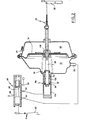
- the system shown schematically in Figure 1 comprises a servomotor 10 composed of a housing 12 in which is movably mounted a piston 11 which divides the housing into two chambers 16 and 18.
- the piston 14 is mechanically connected, for example by a connection to cable 20, to an input member 22 of the vehicle clutch (not shown).
- a return spring internal to the clutch recalls the member for entered in a rest position as shown in dotted lines in FIG. 1.
- the chamber 18 has an orifice 24 permanently open to the atmosphere, preferably via a filter 25.
- the chamber 16 has two orifices 26 and 28.
- a valve 30 controlled as a function of the position of the piston 14 and constituted essentially as follows: a valve seat 32 is defined in the vicinity of the orifice 26 on the side of the chamber 16, and a cover 34 is biased by a spring 36 in the direction of the seat 32, l operculum 34 carries a rod 38 which passes through the seat 32 and projects into the chamber 16 in the direction of the pirton 14.
- the valve 30 will be in the open or closed position. The rest of the structure of the valve 30 will be described in more detail later.
- the control system also includes a distribution valve 40 controlled by the accelerator pedal 42 of the vehicle.
- the valve 30 comprises a housing 44 provided with a bore 46 in which slides a drawer 48 returned by a spring 50 in contact with an extension 52 of the pedal 42.
- the drawer has two ranges 66 and 68 separated by a narrowing 70 which cooperate with the orifices 54, 58, 62 and 64 as will be seen below.
- the pedal 42 is returned to its rest position, as shown, by a spring 72 whose force is such that the slide 48 is moved against the spring 50 in a first position in which there has communication between the first inlet port 54 and the first outlet port 62 and where the other two orifices 58, 64 are blocked.
- the chamber 16 of the booster is placed in communication with the vacuum source 56 and the piston 14 is moved to the left if we consider the figure, by driving the input member 22 of the clutch into the position shown for which the clutch is released, and the driver of the vehicle can then make any gear change at l using the lever (not shown) provided for this purpose.
- the chamber 16 is placed in communication with the atmosphere and the piston 14 moves to the right, considering the figure, under the influence of the internal spring of the clutch.
- the chamber 16 is connected directly to the atmosphere via the orifice 28, and the piston 14 is then completely brought back to the right until in the rest position of the control member 22 of the clutch and which corresponds to its full commitment.
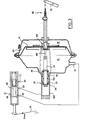
- valve seat 32 is defined on a sheath-shaped insert 102, mounted frictionally in a tubular guide 104 in the following manner: the sheath 102 has two peripheral grooves , the first housing a seal 108 and the second housing a rod 112 force-fitted into the tubular guide 104.
- a unidirectional dead-stroke link 116 At the opposite end 114 of the rod 38 which projects towards the piston 14 is provided a unidirectional dead-stroke link 116, in the following manner: the rod 38 has a projection 118 which extends through an orifice 120 in a cavity 122 of the piston 14 and the projection 118 comprises a flared head 124, of dimension greater than the orifice 120.
- a second valve seat 126 is defined on the insert 102 on the side of the chamber 16 and a second valve cap 128 is mounted on the rod 38 to define a second valve 130.
- the stroke of the piston Y corresponds to the free length of the projection 118 of the rod 38.
- the position of the insert 102 can be constantly and automatically adjusted so that the position of the piston 14 corresponding to the closing of the valve 30 coincides in all circumstances with the sliding position of the clutch.
- insert 102 When the clutch friction linings are replaced, insert 102 must be pushed towards the bottom of guide 104. This can be done simply by pushing piston 14 and rod 38 from the outside. thanks to mechanism 20.
- the insert will be automatically returned to the position corresponding to the sliding of the clutch.
Landscapes
- Engineering & Computer Science (AREA)
- General Engineering & Computer Science (AREA)
- Mechanical Engineering (AREA)
- Physics & Mathematics (AREA)
- Fluid Mechanics (AREA)
- Hydraulic Clutches, Magnetic Clutches, Fluid Clutches, And Fluid Joints (AREA)
Applications Claiming Priority (2)
| Application Number | Priority Date | Filing Date | Title |
|---|---|---|---|
| IT2195682 | 1982-06-21 | ||
| IT21956/82A IT1152257B (it) | 1982-06-21 | 1982-06-21 | Impianto di comando per la frizione d'un autoveicolo |
Publications (3)
| Publication Number | Publication Date |
|---|---|
| EP0097594A2 true EP0097594A2 (de) | 1984-01-04 |
| EP0097594A3 EP0097594A3 (en) | 1984-04-25 |
| EP0097594B1 EP0097594B1 (de) | 1987-04-22 |
Family
ID=11189368
Family Applications (1)
| Application Number | Title | Priority Date | Filing Date |
|---|---|---|---|
| EP83401274A Expired EP0097594B1 (de) | 1982-06-21 | 1983-06-20 | Kupplungssteuersystem für Kraftwagen |
Country Status (3)
| Country | Link |
|---|---|
| EP (1) | EP0097594B1 (de) |
| DE (1) | DE3371110D1 (de) |
| IT (1) | IT1152257B (de) |
Cited By (3)
| Publication number | Priority date | Publication date | Assignee | Title |
|---|---|---|---|---|
| EP0193502A2 (de) | 1985-02-28 | 1986-09-03 | Stefano Venturini | Servo-Reibungskupplungsvorrichtung zum Automatisieren der Kupplungswirkung bei Motorfahrzeugen jeder Art |
| WO1993025824A1 (en) * | 1992-06-05 | 1993-12-23 | Automotive Products Plc | A clutch actuation system and a cable therefor |
| EP0614021A1 (de) * | 1993-03-04 | 1994-09-07 | Eaton Corporation | Kupplungspedal-Dämpfungszylinder Antriebs-Drehmomentbegrenzer |
Family Cites Families (5)
| Publication number | Priority date | Publication date | Assignee | Title |
|---|---|---|---|---|
| GB840261A (en) * | 1957-10-01 | 1960-07-06 | Vauxhall Motors Ltd | Improved clutch assembly |
| FR1279933A (fr) * | 1960-06-22 | 1961-12-29 | Ibm | Mécanisme de réglage en position précise |
| FR1529128A (fr) * | 1966-06-24 | 1968-06-14 | Robertshaw Controls Co | Mécanisme de commande par un fluide |
| LU59226A1 (de) * | 1969-08-04 | 1969-12-22 | ||
| FR2300921A1 (fr) * | 1975-02-12 | 1976-09-10 | Dba | Verin numerique a deux etages |
-
1982
- 1982-06-21 IT IT21956/82A patent/IT1152257B/it active
-
1983
- 1983-06-20 DE DE8383401274T patent/DE3371110D1/de not_active Expired
- 1983-06-20 EP EP83401274A patent/EP0097594B1/de not_active Expired
Cited By (8)
| Publication number | Priority date | Publication date | Assignee | Title |
|---|---|---|---|---|
| EP0193502A2 (de) | 1985-02-28 | 1986-09-03 | Stefano Venturini | Servo-Reibungskupplungsvorrichtung zum Automatisieren der Kupplungswirkung bei Motorfahrzeugen jeder Art |
| EP0193502A3 (en) * | 1985-02-28 | 1987-09-16 | Stefano Venturini | A servo friction-clutch device for automating the clutch operation in motor vehicles of any kind |
| WO1993025824A1 (en) * | 1992-06-05 | 1993-12-23 | Automotive Products Plc | A clutch actuation system and a cable therefor |
| GB2273140A (en) * | 1992-06-05 | 1994-06-08 | Automotive Products Plc | A clutch actuation system and a cable therefor |
| US5404981A (en) * | 1992-06-05 | 1995-04-11 | Automotive Products, Plc | Hydraulic clutch actuation system and method of installing |
| GB2273140B (en) * | 1992-06-05 | 1995-06-07 | Automotive Products Plc | A clutch actuation system and a cable therefor |
| EP0614021A1 (de) * | 1993-03-04 | 1994-09-07 | Eaton Corporation | Kupplungspedal-Dämpfungszylinder Antriebs-Drehmomentbegrenzer |
| US5404982A (en) * | 1993-03-04 | 1995-04-11 | Eaton Corporation | Clutch pedal dashpot driveline torque limiter |
Also Published As
| Publication number | Publication date |
|---|---|
| EP0097594B1 (de) | 1987-04-22 |
| DE3371110D1 (en) | 1987-05-27 |
| IT8221956A0 (it) | 1982-06-21 |
| EP0097594A3 (en) | 1984-04-25 |
| IT1152257B (it) | 1986-12-31 |
Similar Documents
| Publication | Publication Date | Title |
|---|---|---|
| EP0101658B1 (de) | Bremskraftverstärker mit Halteelement für den Ventilsteuerkolben | |
| EP0662894B1 (de) | Bremskraftverstärker mit verzögerter hydraulischer reaktion | |
| EP0097594B1 (de) | Kupplungssteuersystem für Kraftwagen | |
| EP0340059B1 (de) | Bremskraftverstärker mit einstellbarem Schwellenwert | |
| FR2561599A1 (fr) | Servomoteur a depression d'assistance au freinage | |
| EP0004513B1 (de) | Hydropneumatische Vorrichtung zur synchronisierten Betätigung der Kupplung und der Getriebeverriegelung | |
| FR2724354A1 (fr) | Dispositif de freinage assiste a course masquee et a securite accrue | |
| WO2001081142A1 (fr) | Servomoteur pour freinage d'urgence | |
| EP0059139B1 (de) | Servomotor für Bremskraftverstärkung mit reduziertem Betätigungstotgang | |
| WO2002008038A1 (fr) | Servomoteur pour freinage d'urgence comportant des moyens d'insonorisation. | |
| EP0368691A1 (de) | Steuervorrichtung eines Kraftverstärkers, insbesondere für Kraftfahrzeugbremsanlagen | |
| FR2737457A1 (fr) | Servofrein d'automobile | |
| EP1597127B1 (de) | Bremssteuervorrichtung | |
| FR2462741A1 (fr) | Mecanisme de commande de la pression d'un fluide | |
| EP0229545B1 (de) | Betätigungseinrichtung für Heizungs- und Lüftungs- oder Klimaanlagen in Kraftfahrzeugen | |
| FR2696141A1 (fr) | Dispositif de freinage assisté à réaction hydraulique et course masquée. | |
| EP0041885B1 (de) | Hydraulischer Bremskraftverstärker | |
| WO1998022321A1 (fr) | Systeme de feinage assiste a reaction hydraulique amelioree | |
| FR2702437A1 (fr) | Dispositif de freinage assisté à commande automatique simplifiée. | |
| WO1995014597A1 (fr) | Dispositif de freinage assiste a course masquee et a gain garanti | |
| EP1325853A2 (de) | Pneumatischer Bremsservo mit reduzierter Reaktion | |
| EP2384942B1 (de) | Hydraulisches Bremssystem mit einem verbesserten Steuerglied | |
| EP1365949B1 (de) | Kraftfahrzeugbremsvorrichtung | |
| CH144167A (fr) | Dispositif de commande d'un dispositif récepteur, applicable notamment au freinage d'un véhicule. | |
| FR2696143A1 (fr) | Dispositif de freinage assisté à réaction hydraulique ralentie. |
Legal Events
| Date | Code | Title | Description |
|---|---|---|---|
| PUAI | Public reference made under article 153(3) epc to a published international application that has entered the european phase |
Free format text: ORIGINAL CODE: 0009012 |
|
| 17P | Request for examination filed |
Effective date: 19830630 |
|
| AK | Designated contracting states |
Designated state(s): DE FR GB IT SE |
|
| PUAL | Search report despatched |
Free format text: ORIGINAL CODE: 0009013 |
|
| AK | Designated contracting states |
Designated state(s): DE FR GB IT SE |
|
| 17Q | First examination report despatched |
Effective date: 19860127 |
|
| RAP1 | Party data changed (applicant data changed or rights of an application transferred) |
Owner name: BENDIX ITALIA S.P.A. |
|
| ITF | It: translation for a ep patent filed | ||
| GRAA | (expected) grant |
Free format text: ORIGINAL CODE: 0009210 |
|
| AK | Designated contracting states |
Kind code of ref document: B1 Designated state(s): DE FR GB IT SE |
|
| REF | Corresponds to: |
Ref document number: 3371110 Country of ref document: DE Date of ref document: 19870527 |
|
| PLBE | No opposition filed within time limit |
Free format text: ORIGINAL CODE: 0009261 |
|
| STAA | Information on the status of an ep patent application or granted ep patent |
Free format text: STATUS: NO OPPOSITION FILED WITHIN TIME LIMIT |
|
| 26N | No opposition filed | ||
| PGFP | Annual fee paid to national office [announced via postgrant information from national office to epo] |
Ref country code: GB Payment date: 19900608 Year of fee payment: 8 |
|
| PGFP | Annual fee paid to national office [announced via postgrant information from national office to epo] |
Ref country code: FR Payment date: 19900613 Year of fee payment: 8 |
|
| PGFP | Annual fee paid to national office [announced via postgrant information from national office to epo] |
Ref country code: SE Payment date: 19900615 Year of fee payment: 8 |
|
| PGFP | Annual fee paid to national office [announced via postgrant information from national office to epo] |
Ref country code: DE Payment date: 19900731 Year of fee payment: 8 |
|
| PG25 | Lapsed in a contracting state [announced via postgrant information from national office to epo] |
Ref country code: GB Effective date: 19910620 |
|
| PG25 | Lapsed in a contracting state [announced via postgrant information from national office to epo] |
Ref country code: SE Effective date: 19910621 |
|
| ITTA | It: last paid annual fee | ||
| GBPC | Gb: european patent ceased through non-payment of renewal fee | ||
| PG25 | Lapsed in a contracting state [announced via postgrant information from national office to epo] |
Ref country code: FR Effective date: 19920228 |
|
| PG25 | Lapsed in a contracting state [announced via postgrant information from national office to epo] |
Ref country code: DE Effective date: 19920401 |
|
| EUG | Se: european patent has lapsed |
Ref document number: 83401274.2 Effective date: 19920109 |