EP0097723A1 - Automatischer entzerrer und verfahren zu seiner initialisierung - Google Patents
Automatischer entzerrer und verfahren zu seiner initialisierung Download PDFInfo
- Publication number
- EP0097723A1 EP0097723A1 EP83900068A EP83900068A EP0097723A1 EP 0097723 A1 EP0097723 A1 EP 0097723A1 EP 83900068 A EP83900068 A EP 83900068A EP 83900068 A EP83900068 A EP 83900068A EP 0097723 A1 EP0097723 A1 EP 0097723A1
- Authority
- EP
- European Patent Office
- Prior art keywords
- signal
- series
- data
- single pulse
- data series
- Prior art date
- Legal status (The legal status is an assumption and is not a legal conclusion. Google has not performed a legal analysis and makes no representation as to the accuracy of the status listed.)
- Granted
Links
Images


Classifications
-
- H—ELECTRICITY
- H04—ELECTRIC COMMUNICATION TECHNIQUE
- H04L—TRANSMISSION OF DIGITAL INFORMATION, e.g. TELEGRAPHIC COMMUNICATION
- H04L25/00—Baseband systems
- H04L25/02—Details ; arrangements for supplying electrical power along data transmission lines
- H04L25/03—Shaping networks in transmitter or receiver, e.g. adaptive shaping networks
- H04L25/03006—Arrangements for removing intersymbol interference
- H04L25/03012—Arrangements for removing intersymbol interference operating in the time domain
- H04L25/03114—Arrangements for removing intersymbol interference operating in the time domain non-adaptive, i.e. not adjustable, manually adjustable, or adjustable only during the reception of special signals
- H04L25/03133—Arrangements for removing intersymbol interference operating in the time domain non-adaptive, i.e. not adjustable, manually adjustable, or adjustable only during the reception of special signals with a non-recursive structure
Definitions
- the present invention relates to an automatic equalization device provided in a modem in a receiver in a digital data transmission system and to a method of starting-up the automatic equalization device, particularly a method for starting-up an automatic equalization device at a high speed.
- a master station communicates selectively with one of a plurality of the slave stations.
- a transmitter and a receiver of the master station are connected through a telephone transmission line with receivers and transmitters of the slave stations.
- the transmitter of the master station is always connected in an on-line manner with the receivers of the slave stations.
- the master station polls each of the salve station in sequence.
- Such a polled slave station transmits an "acknowledgement" signal in response to a received "request for transmission" signal and subsequently transmits the data if the slave station has data to be transmitted.
- a modem It is necessary for a modem to adjust its receiver characteristics to the characteristics of the telephone transmission line prior to the actual receipt of data from one of the slave stations.
- the characteristics of the telephone transmission line vary for each slave station, primarily because of the change of distance between the master station and slave stations.
- Once the receiver is adjusted to the telephone transmission line it is possible to satisfactorily track the change of line characteristics using known, relatively slow speed methods.
- the receiver first receives the training data there is a great difference in the characteristics of the receiver and the characteristic of the line. Under such start-up conditions, it takes about 2 seconds to adjust the receiver to the line by the known, relatively slow speed tracking method.
- the total adjustment time for one request for transmission equals the unit adjustment time multiplied by the number of the slave stations. This total adjustment time is a key factor which significantly reduces the efficiency of data transmission in prior art systems.
- the signal series i.e., the training signal for the start-up of the equalization device
- CCITT recommendations prescribe the transmission of a binary pseudo random data code (hereinafter referred to as a PN code).
- PN code binary pseudo random data code
- various methods have been proposed in which, to initialize the correction coefficient (tap coefficient) of the equalization device from the PN code, the correlation between the data and the error signal is calculated and used to correct and determine the tap coefficient.
- such methods have disadvantages of requiring a large, complicated circuit for calculating the correlation and requiring a considerably long time for determining the tap coefficient of the equalization device. For example, about 250 msec are required from a request for transmission to the transmission of the data.
- U.S. Patent No. 3,962,637 to David M. Motley et al. proposed a method for the high-speed start-up of an equalization device in a receiver.
- a special signal comprising the three segments mentioned below is used for the training signal for the start-up of the equalization device.
- a tone signal obtained by modulating a carrier signal in a predetermined phase and amplitude is transmitted.
- a signal obtained by modulating the carrier signal by the data series by which data series the transmission timing, i.e., band rate clock period, can be discriminated is transmitted.
- a signal obtained by modulating the carrier signal by single pulse (impulse) data is transmitted.
- the single pulse signal extracted in the third segment has been deformed by the transfer function (impulse response characteristic) of the transmission line.
- the equalization device in the receiver compensates the distortion (deformation) of the signal on the line. Fundamentally, it is ideal that the equalization device have inverse characteristics of the transfer function of the line. Accordingly, in the above-referenced U.S. patent, the tap coefficient is calculated and determined on the basis of the impulse response characteristics of the transmission line extracted in the third segment of the training signal such that the equalization device has inverse characteristics of the line.
- the technique disclosed in the above-referenced U.S. patent greatly reduces the time required for initializing the tap coefficient of the equalization ievice in the receiver compared with the case where the above-described PN code is used. For example, the time required from a request for transmission to transmission of data can be reduced to less than 30 msec.
- the impulse signal extracted in the third segment of the training signal is, in general, asymmetrical with respect to time.
- To obtain the tap coefficient of an equalization device having inverse characteristics using such an asymmetrical signal requires more calculation time than in the case where a symmetric signal is used.
- the signal transmitted on the line in the above-described third segment does not contain the carrier signal except when the single pulse signal exists.
- the phase of carrier signal for demodulation in the first and the second segment is adjusted, the phase is not adjusted in the third segment. Accordingly, there is the disadvantage that the phase cannot necessarily be guaranteed.
- the third segment there is a pcssibility of asynchronism, since no timing signal for sampling is extracted.
- a first object of the present invention is to speed up the start-up of the automatic equalization device in a receiver and thereby improve the efficiency of data transmission in a multipoint communication system.
- a second object of the present invention is to decrease the time necessary for the initialization of the tap coefficients, in an automatic equalization device in which the impulse response characteristic of the line are used for the initialization of the tap coefficients, by providing a first and a second equalizer unit and by making the impulse response characteristics symmetrical with respect to time by the first equalizer unit.
- a third object of the present invention is to provide a method of starting up an automatic equalization device of the above-mentioned type in which the phase of the carrier signal can be guaranteed even in the segment for extracting an impulse response signal.
- a fourth object of the present invention is to provide a method of starting up an automatic equalization device in which the timing signal can be extracted and hence asynchronium can be prevented even in the above-mentioned segment for extracting an impulse signal.
- an automatic equalization device which is arranged in a receiver for receiving through a transmission line and demodulating a signal obtained by quadrature-amplitude modulating a carrier signal by digital data in a transmitter, and which compensates for the distortion introduced into the received signal by the transmission line.
- the automatic equalization device comprises a single pulse extraction circuit for extracting a signal corresponding to a single pulse containing distortion due to the transmission line from a predetermined training signal received for starting up the receiver before receiving the data signal and comprises first and seccnd equalization circuits.
- the single pulse extraction circuit has a means for generating a data series expressing by complex numbers the signal corresponding to the single pulse, a means for normalizing the data series, and a means for deriving the complex conjugates cf the normalized data series.
- the first equalization circuit has a means for calculating an auto-correlation series of the signal corresponding to the single pulse from the normalized data series using the complex conjugate data series as the tap coefficient and has a means for calculating a cross-correlation series between the data signal series received after start-up and the signal corresponding to the single pulse using the complex conjugate data series as the tap coefficient.
- the second equalization circuit has a means for obtaining the N-th order approximate data series of the inverse matrix of the auto-correlation series using the auto-correlation series obtained in the first equalization circuit, a means for obtaining the data series corresponding to the above-mentioned inverse matrix from the N-th order approximate data series by means of the successive approximation method, and a means for obtaining an equalized output from the cross--correlation series of the received data signal supplied from the first equalization circuit by setting the data series corresponding to the inverse matrix as the initialization tap coefficient.
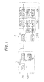
- FIG. 1 A receiver equipped with an automatic equalization device according to the present invention is illustrated in Fig. 1.
- a transmitter 1 receives a transmission request signal (RS), it generates training data in a training data generating unit (TRG) 11 and supplies the training data to the modulation unit (MOD) 12.
- MOD 12 carries out quadrature-amplitude modulation on the carrier signal from a carrier signal generating unit (CRG) 13 based on the training data and transmits the modulated signal to the receiver 2 through the transmission line L.
- the setting of the starting-up condition for receiving the data signal is carried out on basis of the received training signal. Predicting the time when the setting of the starting-up condition will be finished, the transmitter 1 generates a transmission ready signal CS and starts to transmit the signal modulated by the transmitting data SD to the receiver 2.
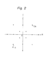
- the modulation unit 12 of the transmitter 1 carries out quadrature amplitudie modulation into 16 values on the carrier signal from the carrier generating unit 13 as shown, for example, in Fig. 2.
- each signal point shown in Fig. 2 corrsponds to the amplitude and phase of the modulated signal and can be expressed in a complex number notation.
- the receiver 2 of Fig. 1 comprises a demodulation unit (DEM) 21 for receiving and demodulating the signal transmitted from transmitter 1, a single pulse extraction unit 22 for extracting a signal corresponding to a single pulse signal from the training data demodulated in the demodulation unit 21, and a first and a second equalizer unit (EQL 1 and EQL 2) started up on the basis of the extracted data corresponding to the single pulse signal.
- DEM demodulation unit
- EQL 1 and EQL 2 a first and a second equalizer unit
- TM is a timing signal for data transmission
- TRD is training data
- TRS is a carrier signal modulated by TRD.
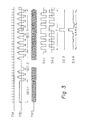
- the training data TRD has three segments SEG1, SEG2, and SEG3.
- the training signal TRS is a signal modulated with constant data and hence has a constant amplitude and a constant phase.
- the demodulation portion (DEM) 21 of the receiver 2 the adjustment of the automatic gain control AGC can be carried out while this first segment SEG1 is received.
- the training signal TRS is modulated alternately with two data "A" and "-A" which have the opposite phase and the same amplitude. For example, such two data "A” and "-A” are shown as D A and D -A in Fig. 2.
- the timing signal for data transmission is extracted from the signal in the second segment SEG2.
- the training data in the third segment SEG3 is alternately expressed as data "A" and "-A” except at time t 3 where the data "A" appears successively.
- SAl shows only a portion of the training data in the third segment SEG3, and SA2 shows that obtained by delaying it by one data symbol.
- FIG. 4 A flow chart of the start-up of the automatic equalization device of the receiver 2 in Fig. 2 using the training signal of Fig. 3 is illustrated in Fig. 4.
- the received data series (expressed in complex numbers) corresponding to the third segment SEG3 of the training signal demodulated in the demodulation unit 2 is supplied to the single palse extraction circuit REP.
- REP the received data series is added to one obtained by delaying that data series by one data symbol.
- This data series P i may be deemed an ideal single pulse shown in Fig. 3 distorted by the transmission line L.
- the data series P J corresponding to the single pulse extracted as described above is supplied to the normalization circuit NR, and is normalized in NR.
- the normalization circuit NR first calculates the magnitude of the data series P J , that is, the 0-th order correlation P 2 , according to the following equation:
- the normalized data series X j is supplied to the complex conjugate derivation circuit CN.
- the derived complex conjugate data series C J is initialized in the first tap coefficient register TPRl as the tap coefficient of the first equalization circuit (EQL1) 23.
- the normalized data series x J and its complex conjugate data series C J are supplied to the computing circuit CNTl of the first equalization circuit 23, and the auto-correlation series Am is calculated.
- the calculation of the auto-correlation series Am is carried out as follows. First, regarding the 0-th order correlation A 0 ,
- the auto-correlation series A m is supplied to the computing circuit CNT2 of the second equalization circuit (EQL2) 24, and the first--crder approximate series B J (1) of the inverse characteristic matrix is obtained as follows.
- the data series B J (1) obtained in the fifth step 5 is used as the tap coefficient B J of the second equalization circuit to calculate the equalized output S with the auto-correlation series A as the tap data. Then, the output S is compared with the reference output series Ref, and the tap coefficient B J is corrected successively so as to make the error approach zero.
- the equalized output S is the data series S L given as follows:
- the correction of the tap coefficient B J is carried out by using the following successive approximation method:
- the tap coefficient B J of the second equalization circuit 24 is initialized and set in the tap coefficient register TPR2.
- the initialization of the tap coefficient of the automatic equalization device is completed. Predicting the time when the start-up in the receiver 2 is completed as described above, the transmitter 1 starts to transmit the transmission data.
- the received data signal is demodulated in the data series in the demodulation unit 21 and supplied to the first equalization circuit 23.
- the first equalized output is calculated from the received data series by the first equalized output circuit OPUl using the tap coefficient C J in the first tap coefficient register TPR1.
- the equalized output data series from the first equalization circuit 23 is supplied to the equalized output circuit OPU2 of the second equalization circuit 24, and the final equalized output data is calculated using the second tap coefficient B J .
- it is possible to form a single equalized output circuit for the received data by calculating a combined tap coefficient from the first tap coefficient C J and the second tap coefficient B J by a convolution operation.
- FIG. 5 An automatic equalization device in accordance with one embodiment of the present invention is illustrated in detail in Fig. 5.
- the received signal after demodulation by the demodulation unit 21, is equalized by the first equalization circuit 23 and the second equalization circuit 24.
- the equalized output is data discriminated in the data discrimination unit 25 and then output as output data.
- the output signal of the demodulation unit 21 is supplied to the single pulse extraction unit 22, and the first and second equalization circuits 23 and 24 are started up in accordance with the extracted single pulse.
- the demodulation unit 21 has a filter circuit (FIL) 211 for removing the noise from the received signal, an automatic gain control circuit (AGC) 212 for adjusting the level of the received signal, a demodulation circuit (DEM) 213 for demodulation of the quadrature-amplitude modulation, and a roll-off filter circuit (ROF) 214 for removing the high frequency component from the demodulated signal.
- FIL filter circuit
- AGC automatic gain control circuit
- DEM demodulation circuit
- ROF roll-off filter circuit
- the single pulse extraction unit 22 has an extraction circuit (REP) 221 for extracting the data series corresponding to the single pulse signal from the training signal, a normalization circuit (NR) 222 for normalizing the extracted data series, and a complex conjugate derivation circuit (CN) 223 for deriving the complex conjugate data series of the normalized data series.
- REP extraction circuit
- NR normalization circuit
- CN complex conjugate derivation circuit
- the first equalization circuit (EQLl) 23 has a first tap data register (TPD1) into which the received data from the demodulation unit 21 is written, a first equalized output circuit (OPUl) 232 for calculating the first equalized output from the first tap data and the first tap coefficient, a first tap coefficient register (TPRl) 234 which is initially set by the output data of the complex conjugate derivation circuit 223, a first computing control circuit (CNT1) 235 for calculating the auto-correlation series of the single pulse signal, and a second tap data register (TPD2) 236 into which the data series from the normalization circuit 222 is written.
- TPD1 first tap data register
- OPUl first equalized output circuit
- TPRl first tap coefficient register
- CNT1 first computing control circuit
- TPD2 second tap data register
- the second equalization circuit (EQL2) 24 has a third tap data register (TPD3) 241 into which the first equalized output data is written, a second equalized output circuit (OPU2) 242 for calculating the second equalized output from the third tap data and the second tap coefficient, a second tap coefficient register (TRP2) 243, a second computing control circuit (CNT2) 244 for calculating the equalized output from the auto--correlation series of the single pulse and the second tap coefficient and for correcting the second tap coefficient in accordance with the error of the equalized output to the reference output Ref, an n-th order approximation circuit (n-th AP) 245 for obtaining the n-th order approximation of the inverse matrix from the auto-correlation series, a fourth tap data register (TPD4) 246 into which the auto-correlation series of the single pulse is written, and an error calculation circuit (EPR2) 247 for calculating the error of the equalized output to the reference output using the auto-correlation series of the single pulse
- the data discrimination unit 25 has a carrier automatic phase control circuit (CAPC) 251, a discrimination circuit 252, and an error calculation circuit (ERR1) 253.
- the circuits in the data discrimination unit 25 are disclosed, for example, in Japanese Patent No. 1,041,066, thus are not described herein.
- the present invention can be applied for increasing the data transmission efficiency in a multipoint communication svstem.
Landscapes
- Engineering & Computer Science (AREA)
- Power Engineering (AREA)
- Computer Networks & Wireless Communication (AREA)
- Signal Processing (AREA)
- Cable Transmission Systems, Equalization Of Radio And Reduction Of Echo (AREA)
Applications Claiming Priority (2)
| Application Number | Priority Date | Filing Date | Title |
|---|---|---|---|
| JP56214604A JPS58121838A (ja) | 1981-12-28 | 1981-12-28 | 自動等化器 |
| JP214604/81 | 1981-12-28 |
Publications (3)
| Publication Number | Publication Date |
|---|---|
| EP0097723A1 true EP0097723A1 (de) | 1984-01-11 |
| EP0097723A4 EP0097723A4 (de) | 1985-09-16 |
| EP0097723B1 EP0097723B1 (de) | 1988-03-30 |
Family
ID=16658457
Family Applications (1)
| Application Number | Title | Priority Date | Filing Date |
|---|---|---|---|
| EP83900068A Expired EP0097723B1 (de) | 1981-12-28 | 1982-12-28 | Automatischer entzerrer und verfahren zu seiner initialisierung |
Country Status (6)
| Country | Link |
|---|---|
| US (1) | US4571733A (de) |
| EP (1) | EP0097723B1 (de) |
| JP (1) | JPS58121838A (de) |
| AU (1) | AU546024B2 (de) |
| DE (1) | DE3278305D1 (de) |
| WO (1) | WO1983002373A1 (de) |
Cited By (5)
| Publication number | Priority date | Publication date | Assignee | Title |
|---|---|---|---|---|
| GB2140657A (en) * | 1983-05-20 | 1984-11-28 | Victor Company Of Japan | Improving waveform of pcm signal eye pattern |
| EP0205378A3 (en) * | 1985-06-04 | 1989-01-11 | Fujitsu Limited | Method and device for timing pull-in of receiving equipment |
| GB2275398A (en) * | 1993-02-19 | 1994-08-24 | Fujitsu Ltd | Modem training patterns |
| GB2296636A (en) * | 1994-12-20 | 1996-07-03 | Fujitsu Ltd | Non-Nyquist transmission training method and apparatus |
| WO1999050969A3 (en) * | 1998-03-27 | 2000-01-13 | Ericsson Telefon Ab L M | Equalizer, using krakovian algebra, for multicarrier transmission |
Families Citing this family (13)
| Publication number | Priority date | Publication date | Assignee | Title |
|---|---|---|---|---|
| JPS59246A (ja) * | 1982-06-17 | 1984-01-05 | Fujitsu Ltd | トレ−ニング方式 |
| JPH0614627B2 (ja) * | 1985-06-04 | 1994-02-23 | 富士通株式会社 | モデムのトレーニング方法 |
| US4825448A (en) * | 1986-08-07 | 1989-04-25 | International Mobile Machines Corporation | Subscriber unit for wireless digital telephone system |
| US4811360A (en) * | 1988-01-14 | 1989-03-07 | General Datacomm, Inc. | Apparatus and method for adaptively optimizing equalization delay of data communication equipment |
| DK168750B1 (da) * | 1990-05-01 | 1994-05-30 | Dancall Telecom As | Fremgangsmåde til modforvrængning i en modtager af signaler, der har passeret en transmissionskanal |
| US5619503A (en) * | 1994-01-11 | 1997-04-08 | Ericsson Inc. | Cellular/satellite communications system with improved frequency re-use |
| US6865221B2 (en) * | 2000-01-07 | 2005-03-08 | Aware, Inc. | Systems and methods for loop length and bridged tap length determination of a transmission line |
| JP2001313594A (ja) * | 2000-04-28 | 2001-11-09 | Fujitsu Ltd | Dmtシステムのタイムドメインイコライザーの係数更新方法、レシーブ方法、dmtシステム及びdmtモデム |
| JP4164363B2 (ja) * | 2001-02-22 | 2008-10-15 | コーニンクレッカ フィリップス エレクトロニクス エヌ ヴィ | 低減された複雑性のキャリア間干渉除去 |
| US8406356B2 (en) | 2007-06-06 | 2013-03-26 | Micron Technology, Inc. | Self-calibrating continuous-time equalization |
| KR101830375B1 (ko) * | 2011-06-07 | 2018-02-21 | 한국전자통신연구원 | 지상파 신호와 모바일 신호 융합형 수신장치 및 방법 |
| US9531569B2 (en) * | 2014-10-08 | 2016-12-27 | Dell Products, Lp | Power aware receiver/transmitter adaptation for high speed serial interfaces |
| US10075286B1 (en) * | 2017-03-13 | 2018-09-11 | Tektronix, Inc. | Equalizer for limited intersymbol interference |
Family Cites Families (6)
| Publication number | Priority date | Publication date | Assignee | Title |
|---|---|---|---|---|
| CH524287A (de) * | 1970-09-25 | 1972-06-15 | Patelhold Patentverwertung | Verfahren zur automatischen Einstellung eines Transversalfilters zur Impulsentzerrung |
| US4047013A (en) * | 1975-07-09 | 1977-09-06 | International Business Machines Corporation | Method and apparatus for fast determination of initial transversal equalizer coefficient values |
| FR2337465A1 (fr) * | 1975-12-30 | 1977-07-29 | Ibm France | Procede et dispositif pour determiner les valeurs initiales des coefficients d'un egaliseur transversal complexe |
| JPS5744339A (en) * | 1980-08-29 | 1982-03-12 | Hitachi Ltd | Signal processing system |
| US4430743A (en) * | 1980-11-17 | 1984-02-07 | Nippon Electric Co., Ltd. | Fast start-up system for transversal equalizers |
| JPH05283010A (ja) * | 1992-03-31 | 1993-10-29 | Matsushita Electric Ind Co Ltd | ガス放電型表示パネル |
-
1981
- 1981-12-28 JP JP56214604A patent/JPS58121838A/ja active Granted
-
1982
- 1982-12-28 AU AU10439/83A patent/AU546024B2/en not_active Ceased
- 1982-12-28 EP EP83900068A patent/EP0097723B1/de not_active Expired
- 1982-12-28 WO PCT/JP1982/000479 patent/WO1983002373A1/ja not_active Ceased
- 1982-12-28 DE DE8383900068T patent/DE3278305D1/de not_active Expired
- 1982-12-28 US US06/527,573 patent/US4571733A/en not_active Expired - Lifetime
Non-Patent Citations (1)
| Title |
|---|
| See references of WO8302373A1 * |
Cited By (12)
| Publication number | Priority date | Publication date | Assignee | Title |
|---|---|---|---|---|
| GB2140657A (en) * | 1983-05-20 | 1984-11-28 | Victor Company Of Japan | Improving waveform of pcm signal eye pattern |
| US4637036A (en) * | 1983-05-20 | 1987-01-13 | Victor Company Of Japan, Limited | Circuit arrangement for a data acquisition circuit of a PCM processor and a method for improving waveform of PCM signal eye pattern |
| EP0205378A3 (en) * | 1985-06-04 | 1989-01-11 | Fujitsu Limited | Method and device for timing pull-in of receiving equipment |
| GB2275398A (en) * | 1993-02-19 | 1994-08-24 | Fujitsu Ltd | Modem training patterns |
| US5537437A (en) * | 1993-02-19 | 1996-07-16 | Fujitsu Limited | Initialization equalization for modulation and demodulation using special training pattern |
| GB2275398B (en) * | 1993-02-19 | 1997-02-05 | Fujitsu Ltd | Initialization method for modulation and demodulation system using special training pattern |
| GB2296636A (en) * | 1994-12-20 | 1996-07-03 | Fujitsu Ltd | Non-Nyquist transmission training method and apparatus |
| GB2296636B (en) * | 1994-12-20 | 1999-09-29 | Fujitsu Ltd | Non-nyquist transmission training method and apparatus |
| US6021160A (en) * | 1994-12-20 | 2000-02-01 | Fujitsu Limited | Training method for non-nyquist transmission system and training data transmission apparatus for non-nyquist transmission system |
| WO1999050969A3 (en) * | 1998-03-27 | 2000-01-13 | Ericsson Telefon Ab L M | Equalizer, using krakovian algebra, for multicarrier transmission |
| US6185251B1 (en) | 1998-03-27 | 2001-02-06 | Telefonaktiebolaget Lm Ericsson | Equalizer for use in multi-carrier modulation systems |
| US6408022B1 (en) | 1998-03-27 | 2002-06-18 | Telefonaktiebolaget L M Ericsson | Equalizer for use in multi-carrier modulation systems |
Also Published As
| Publication number | Publication date |
|---|---|
| JPS58121838A (ja) | 1983-07-20 |
| US4571733A (en) | 1986-02-18 |
| JPS648498B2 (de) | 1989-02-14 |
| EP0097723A4 (de) | 1985-09-16 |
| AU546024B2 (en) | 1985-08-08 |
| EP0097723B1 (de) | 1988-03-30 |
| WO1983002373A1 (fr) | 1983-07-07 |
| DE3278305D1 (en) | 1988-05-05 |
Similar Documents
| Publication | Publication Date | Title |
|---|---|---|
| EP0097723B1 (de) | Automatischer entzerrer und verfahren zu seiner initialisierung | |
| US5870438A (en) | Fast resynchronization system for high-speed data transmission | |
| US4868850A (en) | MODEM communication system having training means and method for training same | |
| US4262360A (en) | Method and device for detecting a pseudo-random sequence of carrier phase changes of 0° and 180° in a data receiver | |
| US4416015A (en) | Timing acquisition in voiceband data sets | |
| EP0430531B1 (de) | Technik zur Bestimmung der Zerstreuungscharakteristiken eines Signals in Fernmeldesystemen | |
| CA1134459A (en) | Synchronization of a data communication receiver with a received signal | |
| EP0496677B1 (de) | Adaptive Entzerrer | |
| US4403331A (en) | Method and apparatus for transmitting data over limited bandwidth channels | |
| US5369668A (en) | Fast response matched filter receiver with decision feedback equalizer | |
| US4539689A (en) | Fast learn digital adaptive equalizer | |
| US4253186A (en) | Method and device for detecting a pseudo-random sequence of two symbols in a data receiver employing double sideband-quadrature carrier modulation | |
| US5404379A (en) | Timing recovery method and system | |
| JPS5938780B2 (ja) | デジタル・モデムを同期する方式 | |
| US4227252A (en) | Method and device for acquiring the initial phase of the clock in a synchronous data receiver | |
| JPH0216621B2 (de) | ||
| JPS6141233A (ja) | 多点ネツトワークの自動同定方法および装置 | |
| US6731710B1 (en) | Method for rapid carrier frequency estimation in a communication system | |
| US6324234B1 (en) | Synchronization and clock recovery | |
| EP0491403A2 (de) | Vorrichtung zur Bestimmung der Trägerfrequenz eines digitalen Signals | |
| JPH0770970B2 (ja) | 適応等化器 | |
| US5077755A (en) | Digital signal processing system in modem | |
| JPS648937B2 (de) | ||
| US5278867A (en) | Receiver system for processing signals received on diversity channels | |
| CA1157917A (en) | Fast learn digital adaptive equalizer |
Legal Events
| Date | Code | Title | Description |
|---|---|---|---|
| PUAI | Public reference made under article 153(3) epc to a published international application that has entered the european phase |
Free format text: ORIGINAL CODE: 0009012 |
|
| 17P | Request for examination filed |
Effective date: 19830816 |
|
| AK | Designated contracting states |
Designated state(s): DE FR GB NL |
|
| 17Q | First examination report despatched |
Effective date: 19860829 |
|
| GRAA | (expected) grant |
Free format text: ORIGINAL CODE: 0009210 |
|
| AK | Designated contracting states |
Kind code of ref document: B1 Designated state(s): DE FR GB NL |
|
| REF | Corresponds to: |
Ref document number: 3278305 Country of ref document: DE Date of ref document: 19880505 |
|
| ET | Fr: translation filed | ||
| PLBE | No opposition filed within time limit |
Free format text: ORIGINAL CODE: 0009261 |
|
| STAA | Information on the status of an ep patent application or granted ep patent |
Free format text: STATUS: NO OPPOSITION FILED WITHIN TIME LIMIT |
|
| 26N | No opposition filed | ||
| PGFP | Annual fee paid to national office [announced via postgrant information from national office to epo] |
Ref country code: NL Payment date: 19971223 Year of fee payment: 16 |
|
| PGFP | Annual fee paid to national office [announced via postgrant information from national office to epo] |
Ref country code: FR Payment date: 19981209 Year of fee payment: 17 |
|
| PGFP | Annual fee paid to national office [announced via postgrant information from national office to epo] |
Ref country code: GB Payment date: 19981231 Year of fee payment: 17 |
|
| PGFP | Annual fee paid to national office [announced via postgrant information from national office to epo] |
Ref country code: DE Payment date: 19990107 Year of fee payment: 17 |
|
| PG25 | Lapsed in a contracting state [announced via postgrant information from national office to epo] |
Ref country code: NL Free format text: LAPSE BECAUSE OF NON-PAYMENT OF DUE FEES Effective date: 19990701 |
|
| NLV4 | Nl: lapsed or anulled due to non-payment of the annual fee |
Effective date: 19990701 |
|
| PG25 | Lapsed in a contracting state [announced via postgrant information from national office to epo] |
Ref country code: GB Free format text: LAPSE BECAUSE OF NON-PAYMENT OF DUE FEES Effective date: 19991228 |
|
| GBPC | Gb: european patent ceased through non-payment of renewal fee |
Effective date: 19991228 |
|
| PG25 | Lapsed in a contracting state [announced via postgrant information from national office to epo] |
Ref country code: FR Free format text: LAPSE BECAUSE OF NON-PAYMENT OF DUE FEES Effective date: 20000831 |
|
| PG25 | Lapsed in a contracting state [announced via postgrant information from national office to epo] |
Ref country code: DE Free format text: LAPSE BECAUSE OF NON-PAYMENT OF DUE FEES Effective date: 20001003 |
|
| REG | Reference to a national code |
Ref country code: FR Ref legal event code: ST |