EP0098023B1 - Verfahren und Anlage für die anaerobe Ausfaulung von organischen Reststoffen wie Jauche - Google Patents
Verfahren und Anlage für die anaerobe Ausfaulung von organischen Reststoffen wie Jauche Download PDFInfo
- Publication number
- EP0098023B1 EP0098023B1 EP19830200944 EP83200944A EP0098023B1 EP 0098023 B1 EP0098023 B1 EP 0098023B1 EP 19830200944 EP19830200944 EP 19830200944 EP 83200944 A EP83200944 A EP 83200944A EP 0098023 B1 EP0098023 B1 EP 0098023B1
- Authority
- EP
- European Patent Office
- Prior art keywords
- space
- gas
- tunnel
- liquid
- wall
- Prior art date
- Legal status (The legal status is an assumption and is not a legal conclusion. Google has not performed a legal analysis and makes no representation as to the accuracy of the status listed.)
- Expired
Links
- 239000007788 liquid Substances 0.000 title claims abstract description 69
- 238000000855 fermentation Methods 0.000 title claims abstract description 42
- 239000000463 material Substances 0.000 title claims abstract description 21
- 238000000034 method Methods 0.000 title claims abstract description 19
- 210000003608 fece Anatomy 0.000 title claims abstract description 12
- 239000010871 livestock manure Substances 0.000 title claims abstract description 12
- 239000010815 organic waste Substances 0.000 title claims abstract description 7
- VNWKTOKETHGBQD-UHFFFAOYSA-N methane Chemical compound C VNWKTOKETHGBQD-UHFFFAOYSA-N 0.000 claims abstract description 84
- 230000004151 fermentation Effects 0.000 claims abstract description 39
- 230000007062 hydrolysis Effects 0.000 claims abstract description 20
- 238000006460 hydrolysis reaction Methods 0.000 claims abstract description 20
- 230000029087 digestion Effects 0.000 claims abstract description 7
- 239000002699 waste material Substances 0.000 claims abstract description 5
- 238000010438 heat treatment Methods 0.000 claims description 6
- 238000004891 communication Methods 0.000 claims description 4
- 239000012530 fluid Substances 0.000 claims description 3
- 230000011664 signaling Effects 0.000 claims 1
- 230000020477 pH reduction Effects 0.000 abstract description 21
- CURLTUGMZLYLDI-UHFFFAOYSA-N Carbon dioxide Chemical compound O=C=O CURLTUGMZLYLDI-UHFFFAOYSA-N 0.000 description 8
- 238000002156 mixing Methods 0.000 description 5
- 229960004424 carbon dioxide Drugs 0.000 description 4
- 229910002092 carbon dioxide Inorganic materials 0.000 description 4
- 239000001569 carbon dioxide Substances 0.000 description 4
- 238000007667 floating Methods 0.000 description 4
- 239000007787 solid Substances 0.000 description 4
- 238000003756 stirring Methods 0.000 description 4
- 239000000126 substance Substances 0.000 description 4
- 241000894006 Bacteria Species 0.000 description 3
- 229910000746 Structural steel Inorganic materials 0.000 description 3
- 230000008878 coupling Effects 0.000 description 3
- 238000010168 coupling process Methods 0.000 description 3
- 238000005859 coupling reaction Methods 0.000 description 3
- 230000007423 decrease Effects 0.000 description 2
- 230000003247 decreasing effect Effects 0.000 description 2
- 239000002054 inoculum Substances 0.000 description 2
- 239000000203 mixture Substances 0.000 description 2
- 239000002245 particle Substances 0.000 description 2
- 239000004033 plastic Substances 0.000 description 2
- 238000005086 pumping Methods 0.000 description 2
- 239000010802 sludge Substances 0.000 description 2
- 238000012546 transfer Methods 0.000 description 2
- 239000004677 Nylon Substances 0.000 description 1
- 238000009530 blood pressure measurement Methods 0.000 description 1
- 238000007664 blowing Methods 0.000 description 1
- 239000011449 brick Substances 0.000 description 1
- 230000006835 compression Effects 0.000 description 1
- 238000007906 compression Methods 0.000 description 1
- 230000001419 dependent effect Effects 0.000 description 1
- 238000007599 discharging Methods 0.000 description 1
- 238000002474 experimental method Methods 0.000 description 1
- 239000004744 fabric Substances 0.000 description 1
- 239000006260 foam Substances 0.000 description 1
- 239000003365 glass fiber Substances 0.000 description 1
- 229910052500 inorganic mineral Inorganic materials 0.000 description 1
- 238000009413 insulation Methods 0.000 description 1
- 235000000396 iron Nutrition 0.000 description 1
- 238000012423 maintenance Methods 0.000 description 1
- 238000004519 manufacturing process Methods 0.000 description 1
- 230000000696 methanogenic effect Effects 0.000 description 1
- 239000011707 mineral Substances 0.000 description 1
- 235000010755 mineral Nutrition 0.000 description 1
- 229920001778 nylon Polymers 0.000 description 1
- 230000000737 periodic effect Effects 0.000 description 1
- 239000003566 sealing material Substances 0.000 description 1
- 238000000926 separation method Methods 0.000 description 1
- XLYOFNOQVPJJNP-UHFFFAOYSA-N water Substances O XLYOFNOQVPJJNP-UHFFFAOYSA-N 0.000 description 1
- 210000002268 wool Anatomy 0.000 description 1
Images


Classifications
-
- C—CHEMISTRY; METALLURGY
- C02—TREATMENT OF WATER, WASTE WATER, SEWAGE, OR SLUDGE
- C02F—TREATMENT OF WATER, WASTE WATER, SEWAGE, OR SLUDGE
- C02F3/00—Biological treatment of water, waste water, or sewage
- C02F3/02—Aerobic processes
-
- C—CHEMISTRY; METALLURGY
- C12—BIOCHEMISTRY; BEER; SPIRITS; WINE; VINEGAR; MICROBIOLOGY; ENZYMOLOGY; MUTATION OR GENETIC ENGINEERING
- C12M—APPARATUS FOR ENZYMOLOGY OR MICROBIOLOGY; APPARATUS FOR CULTURING MICROORGANISMS FOR PRODUCING BIOMASS, FOR GROWING CELLS OR FOR OBTAINING FERMENTATION OR METABOLIC PRODUCTS, i.e. BIOREACTORS OR FERMENTERS
- C12M21/00—Bioreactors or fermenters specially adapted for specific uses
- C12M21/04—Bioreactors or fermenters specially adapted for specific uses for producing gas, e.g. biogas
-
- C—CHEMISTRY; METALLURGY
- C12—BIOCHEMISTRY; BEER; SPIRITS; WINE; VINEGAR; MICROBIOLOGY; ENZYMOLOGY; MUTATION OR GENETIC ENGINEERING
- C12M—APPARATUS FOR ENZYMOLOGY OR MICROBIOLOGY; APPARATUS FOR CULTURING MICROORGANISMS FOR PRODUCING BIOMASS, FOR GROWING CELLS OR FOR OBTAINING FERMENTATION OR METABOLIC PRODUCTS, i.e. BIOREACTORS OR FERMENTERS
- C12M23/00—Constructional details, e.g. recesses, hinges
- C12M23/26—Constructional details, e.g. recesses, hinges flexible
-
- C—CHEMISTRY; METALLURGY
- C12—BIOCHEMISTRY; BEER; SPIRITS; WINE; VINEGAR; MICROBIOLOGY; ENZYMOLOGY; MUTATION OR GENETIC ENGINEERING
- C12M—APPARATUS FOR ENZYMOLOGY OR MICROBIOLOGY; APPARATUS FOR CULTURING MICROORGANISMS FOR PRODUCING BIOMASS, FOR GROWING CELLS OR FOR OBTAINING FERMENTATION OR METABOLIC PRODUCTS, i.e. BIOREACTORS OR FERMENTERS
- C12M23/00—Constructional details, e.g. recesses, hinges
- C12M23/34—Internal compartments or partitions
-
- C—CHEMISTRY; METALLURGY
- C12—BIOCHEMISTRY; BEER; SPIRITS; WINE; VINEGAR; MICROBIOLOGY; ENZYMOLOGY; MUTATION OR GENETIC ENGINEERING
- C12M—APPARATUS FOR ENZYMOLOGY OR MICROBIOLOGY; APPARATUS FOR CULTURING MICROORGANISMS FOR PRODUCING BIOMASS, FOR GROWING CELLS OR FOR OBTAINING FERMENTATION OR METABOLIC PRODUCTS, i.e. BIOREACTORS OR FERMENTERS
- C12M23/00—Constructional details, e.g. recesses, hinges
- C12M23/36—Means for collection or storage of gas; Gas holders
-
- C—CHEMISTRY; METALLURGY
- C12—BIOCHEMISTRY; BEER; SPIRITS; WINE; VINEGAR; MICROBIOLOGY; ENZYMOLOGY; MUTATION OR GENETIC ENGINEERING
- C12M—APPARATUS FOR ENZYMOLOGY OR MICROBIOLOGY; APPARATUS FOR CULTURING MICROORGANISMS FOR PRODUCING BIOMASS, FOR GROWING CELLS OR FOR OBTAINING FERMENTATION OR METABOLIC PRODUCTS, i.e. BIOREACTORS OR FERMENTERS
- C12M23/00—Constructional details, e.g. recesses, hinges
- C12M23/38—Caps; Covers; Plugs; Pouring means
-
- C—CHEMISTRY; METALLURGY
- C12—BIOCHEMISTRY; BEER; SPIRITS; WINE; VINEGAR; MICROBIOLOGY; ENZYMOLOGY; MUTATION OR GENETIC ENGINEERING
- C12M—APPARATUS FOR ENZYMOLOGY OR MICROBIOLOGY; APPARATUS FOR CULTURING MICROORGANISMS FOR PRODUCING BIOMASS, FOR GROWING CELLS OR FOR OBTAINING FERMENTATION OR METABOLIC PRODUCTS, i.e. BIOREACTORS OR FERMENTERS
- C12M23/00—Constructional details, e.g. recesses, hinges
- C12M23/52—Mobile; Means for transporting the apparatus
-
- C—CHEMISTRY; METALLURGY
- C12—BIOCHEMISTRY; BEER; SPIRITS; WINE; VINEGAR; MICROBIOLOGY; ENZYMOLOGY; MUTATION OR GENETIC ENGINEERING
- C12M—APPARATUS FOR ENZYMOLOGY OR MICROBIOLOGY; APPARATUS FOR CULTURING MICROORGANISMS FOR PRODUCING BIOMASS, FOR GROWING CELLS OR FOR OBTAINING FERMENTATION OR METABOLIC PRODUCTS, i.e. BIOREACTORS OR FERMENTERS
- C12M45/00—Means for pre-treatment of biological substances
- C12M45/06—Means for pre-treatment of biological substances by chemical means or hydrolysis
-
- C—CHEMISTRY; METALLURGY
- C02—TREATMENT OF WATER, WASTE WATER, SEWAGE, OR SLUDGE
- C02F—TREATMENT OF WATER, WASTE WATER, SEWAGE, OR SLUDGE
- C02F2103/00—Nature of the water, waste water, sewage or sludge to be treated
- C02F2103/20—Nature of the water, waste water, sewage or sludge to be treated from animal husbandry
-
- Y—GENERAL TAGGING OF NEW TECHNOLOGICAL DEVELOPMENTS; GENERAL TAGGING OF CROSS-SECTIONAL TECHNOLOGIES SPANNING OVER SEVERAL SECTIONS OF THE IPC; TECHNICAL SUBJECTS COVERED BY FORMER USPC CROSS-REFERENCE ART COLLECTIONS [XRACs] AND DIGESTS
- Y02—TECHNOLOGIES OR APPLICATIONS FOR MITIGATION OR ADAPTATION AGAINST CLIMATE CHANGE
- Y02E—REDUCTION OF GREENHOUSE GAS [GHG] EMISSIONS, RELATED TO ENERGY GENERATION, TRANSMISSION OR DISTRIBUTION
- Y02E50/00—Technologies for the production of fuel of non-fossil origin
- Y02E50/30—Fuel from waste, e.g. synthetic alcohol or diesel
-
- Y—GENERAL TAGGING OF NEW TECHNOLOGICAL DEVELOPMENTS; GENERAL TAGGING OF CROSS-SECTIONAL TECHNOLOGIES SPANNING OVER SEVERAL SECTIONS OF THE IPC; TECHNICAL SUBJECTS COVERED BY FORMER USPC CROSS-REFERENCE ART COLLECTIONS [XRACs] AND DIGESTS
- Y02—TECHNOLOGIES OR APPLICATIONS FOR MITIGATION OR ADAPTATION AGAINST CLIMATE CHANGE
- Y02W—CLIMATE CHANGE MITIGATION TECHNOLOGIES RELATED TO WASTEWATER TREATMENT OR WASTE MANAGEMENT
- Y02W10/00—Technologies for wastewater treatment
- Y02W10/10—Biological treatment of water, waste water, or sewage
-
- Y—GENERAL TAGGING OF NEW TECHNOLOGICAL DEVELOPMENTS; GENERAL TAGGING OF CROSS-SECTIONAL TECHNOLOGIES SPANNING OVER SEVERAL SECTIONS OF THE IPC; TECHNICAL SUBJECTS COVERED BY FORMER USPC CROSS-REFERENCE ART COLLECTIONS [XRACs] AND DIGESTS
- Y10—TECHNICAL SUBJECTS COVERED BY FORMER USPC
- Y10S—TECHNICAL SUBJECTS COVERED BY FORMER USPC CROSS-REFERENCE ART COLLECTIONS [XRACs] AND DIGESTS
- Y10S435/00—Chemistry: molecular biology and microbiology
- Y10S435/801—Anerobic cultivation
Definitions
- the invention relates to a method and a device for the anaerobic fermentation of organic waste material such as manure in a substantially liquid condition.
- the present invention aims at improving this and at providing a method and a device which are very efficient require low costs and energy and are simple in mounting, structure, operation and maintenance.
- a method as given in the preamble is according to the invention characterized in that the waste material in a liquid condition adapted to be pumped easily is introduced in an acidifying space, in which the gas generated therein is trapped and collected below a roofing of said space separating said space from a adjacent methane fermentation space, the pressure of the gas collected below said roofing forcing said liquid from said acidifying space into said methane fermentation space through an opening in the lower part of the wall of said roofing below the gas collecting space therein, the gas being discharged from below said roofing.
- the invention is realized in such a way that the gas from below said roofing is at least in part introduced into the liquid in the methane fermentation space. If this is done gradually, this gives a good and not too strong stirring of the liquid in the methane fermentation space. In many cases it is however, preferable not to do this exclusively gradually, but periodically and by sudden blows of discharge. This has several advantages. Often a rather dense and closed floating layer of material in a somewhat scum-like condition is formed on the liquid in the methane fermentation space and this is by such periodic and sudden blows broken up adequately by the gas and disintegrated. The warmer gas heats the liquid.
- the invention also allows easy means to have hydrolysis and acidification take place in separate spaces, which improves the method further, as will be described below.
- a device for the anaerobic digestion of organic waste material such as manure in a substantially liquid condition comprises a digestion container, in which in the lower part a tunnel is provided, into which the supply of liquid to be treated opens, said tunnel having a roof which, together with part of its upstanding sidewalls form a collecting space for gas with their lower and inner surface parts, said tunnel having an opening near its lower part giving liquid communication to a methane fermentation space extending alongside and at least in part above said tunnel.
- Such a device has several advantages, in part as described above, and moreover it may entirely or to a considerable part be made of flexible, foldable or windable material so that it may easily be transported and mounted and be particularly suited for operating under a somewhat increased pressure, so that the gas leaves the device at a pressure which is adequate for further use, said higher pressure maintaining the flexible walls of the device in the desired "blown-up" shape.
- This also gives easily a considerable storing space for the gas.
- By such flexible walls they will easily change their shape somewhat depending on pressures and amount of liquid therein so that by .movements of such flexible walls sticking of solid parts to said walls is counteracted.
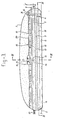
- Fig. 1 is a vertical longitudinal section through such a device
- the device of Figs. 1 to 3 comprises a wall 1 of flexible material, for instance a nylon fabric, coated with and/or impregnated by a gastight plastic layer, for instance of pvc. Flexible parts of the device which will be described below may also consist entirely or in part of such material.
- the wall 1 moreover has an external or internal heat insulation not shown, which may be formed by an enveloping blanket of glass fibre wool and/ or by an internal and/or external insulating layer adhering to the wall, for instance, consisting of a flexible foam plastic material.
- a hose connection 2 with valve and easily operable tube or hose coupling opens in a central plane in the lower part of a short end of the wall.
- a tunnel wall 3 is provided connected sealingly to the outer wall 1 around the hose connection 2 and connected with its lower edges to the bottom of the device. At its end opposite connection 2, this tunnel wall terminates at a short distance from wall 1 to form an opening 4.
- said tunnel wall 3 there is, substantially concentrically therewith, a second tunnel wall 5, extending over the entire length of the wall 1 and connected at both ends sealingly thereto, while its lower ends are sealingly connected to the bottom of the device.
- Said longitudinal lower edges have openings 6 which, as appears from Figs. 1 and 2, are not uniformly distributed over the length thereof, but at the left give more total opening area than towards the right, which may be obtained by a difference in size of each opening, but which in the drawing is obtained by a difference in mutual distances between the openings.
- tunnel wall 3 may be connected to the tunnel wall 5 so that in the central area they form only single roofpart. If the tunnel wall 3 is entirely separate from the tunnel wall 5, as shown by uninterrupted lines in Figs. 1 and 3, the upper part of tunnel wall 3 may be supended for instance by wires from the upper or roofpart of tunnel wall 5, so that tunnel wall 3 does not hang down and sink onto the liquid surface if this is lower than the top part of tunnel wall 3.
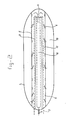
- a heating tube 7 is provided below tunnel wall 5 , which, as appears from Fig. 2, enters the wall 1 through the wide hose connection 2 to enter the space below the tunnel wall 3, then branches into two tubes or hoses, each leaving this space through opening 4 and which are then bent back to a hairpincurve to extend below tunnel wall 5 outside tunnel wall 3 and so leave the wall at the same side where this tube entered the device.
- a gas duct 8 (Fig. 1), in which there is a three-way valve 9, to a header or distributing duct part not shown, connected to a number of flexible hoses 10 extending parallel to the longitudinal direction of the wall 1 and are connected to said wall near both ends. These hoses have openings to discharge gas into the surrounding space.
- the three-way valve 9 in one position connects the space below tunnel wall 5 to the outside air or to suitable collecting means not shown, as indicated by 9', in which case the hoses 10 are closed by said valve.
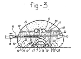
- a single flexible duct 21 is connected to the gas duct 8 (Fig. 3), which duct 8 replaces all ducts 10 or most of them and which serves as an internal distributing duct for the gas.
- This duct is connected near both ends with the wall 1 and has a number of preferably flexible transverse ducts 22 closed at their ends.
- wires 23 extend between each of said transverse ducts and lower points, preferably points on tunnel wall 5 and said wires may for instance each engage the upper edge of an opening 6 in said wall.
- Gas discharge openings are provided in said transverse ducts, preferably in the lower part thereof, so that as much gas as possible remains therein to keep this ductsystem in place by floating if they are embodied as flexible hoses. If there is no gas in these transverse ducts they may hang down, but this is of no harm as they will easily regain the position shown if gas is again introduced therein.
- An air tube 11 for instance the inner tube for a car tyre, floats on the liquid surface 20 in the device and carries a gas discharge duct 12 guided through the wall 1 to the outside (Fig. 3) and there having a valve 13.
- the valve 15 of tube 11 (Fig. 1) is connected to a duct 14 for inflating the tube 11 by air under pressure and guided through the thicker duct 12 to the outside. It is thus possible to inflate the tube during operation and to check the air pressure therein.
- wall 1 extends all around the device so as also to form the bottom thereof.
- the device may be transported to the site where it has to be used in empty and deflated condition and even folded or wound up into a roll.
- On the site it may be positioend e.g. on a concrete floor with a heat insulating layer thereon, or in a ditch with gradually sloping walls.
- this device may be inflated to take up the desired shape about as shown. All connections are now made.
- the heating tube 7 is not embodied as a flexible tube it is now mounted, for instance by entering it through openings in the wall 1, which are thereafter adequately sealed and there may be suitable hose or tube couplings near both ends of the wall 1. In this case it may be desired to position only the straight ends of the tubes 7 within the wall 1, all curves, couplings and connections being positioned outside the wall 1. As however the temperature of the heating fluid need not be higher than 55°C, it is very well possible to make the tube 7 flexible and to mount it in the wall 1 when manufacturing the device, so that also tube 7 may be folded or wound up together with the other parts of the device. If desired a heat insulating blanket is provided over wall 1.
- Liquid to be treated such as liquid manure, being manure diluted by water and if desired having the solid particles therein ground, chopped or cut to much smaller size so that the entire substance behaves substantially as a liquid, is pumped into the device through connection 2. If this substance itself does not have enough methanogenic bacteria, active sludge or an other suitable inoculum may be added.-If desired the device is first filled up to about half its volume with a suitable inoculum manure, which may be manure already treated in such a device previously. Heating fluid is guided through tube 7 to bring the contents at the desired temperature, which in normal operation is for instance 30°C for the methane fermentation space 18 and for instance about 40°C for the space for hydrolysis and acidification below wall 5.
- this space 16 mainly acts as the space for hydrolysis. Liquid therefrom is displaced to space 17 between tunnel walls 3 and 5, which material is ripe for acidification, which thus, takes place mainly in space 17.
- gas is formed, mainly during acidification, and this is mainly carbon dioxide with some methane. This is collected below the upper part of tunnel wall 5 and it forces the liquid gradually from space 17 to space 18 to the side thereof and above it, being the methane fermentation space, through the openings 6. If this is continued too long, finally also gas will pass through openings 6, but this phenomenon forms a brake for itself because with increasing gas quantity the liquid below tunnel walls 3 and 5 decreases, so that less gas is generated. Moreover it is strongly recommeded to open the gas valve 9 in gas duct 8 in a further stage, preferably suddenly and only during the short period.
- the liquid level in tunnels 16 and 17 thus decreases gradually and then rises suddenly by said sudden gas discharge.
- This gas discharge may be controlled by measuring the height of liquid level 19 so that each time this reaches a certain height when moving downwardly, a signal is given to open valve 9 during a short period. It is also possible to have time switching means to open said gas discharge according to a predetermined time pattern.
- the openings in the hoses or tubes 10 may be provided at distances of for instance 50 cm from each other and may have a diameter of for instance about 8 mm. They may be provided at the lower side of said hoses or tubes, so that less liquid enters these tubes if they do not discharge gas and so that the gas will rise as bubbles both to the left and to the right along said ducts.
- gas is formed, mainly methane, and all the gas collects in the upper part of the device below wall 1 above liquid level 20. It is possible to discharge this gas continually, preferably at a suitable pressure adapted for further use without compression, through duct 12. If gas generation is at a too low level, the discharge may be stopped or decreased.
- treated manure or the like may be discharged from the device at intervals, for instance together with or shortly before or after the introduction of new liquid to be treated, continuously or at any desired moment. It is also possible to apply an automatically operating overflow or weir system with a standpipe, for instance a hose connected to a pole outside the device, extending to such a height that the desired pressure in the device is maintained.
- the treated liquid discharged may be spread over meadows.
- a ball or similar float 24 has been shown, which has wires to support a hose 25 which opens at its lower end in an opening 6 of tunnel wall 5 between the end opening 4 and the adjacent shorter end wall of wall 1, so at the right in Fig. 1.
- the hose 25 has its open upper end at a short distance below float 24.
- All kinds of measuring, control and signal ducts may be applied if desired. They may be guided at least for the greater part through openings already there for other purposes, for instance through duct 12, so that in wall 1 the smallest possible number of openings is necessary.
- the device does not have a flexible wall entirely enclosing the space within it, but the flexible wall 1 is connected all around to a concrete floor slab 28, for which purpose a rectangular angle iron beam frame 29 is connected thereto, e.g. by studs 30 embedded in the concrete thereof.
- This concrete slab 28 may rest on a heat insulating layer, e.g. of fibrous mineral material, not shown.
- a layer 31 of resilient sealing material such as rubber.
- the frame 29 is secured to the floor slab 28.
- the flexible wall is clamped between the upstanding leg of the angle iron of frame 29 and a strip 32 by bolts and nuts drawing these parts together.
- the tunnel wall 5 for defining an acidifying space 17 below it is also of flexible gas tight material and is clamped between an angle iron frame 33 and a strip 34, but frame 33, supported by studs 35 in the concrete floor and nuts screwed thereon both on top of and below the horizontal flange of angle irons 33, is supported at a short distance above the concrete floor so as to leave an opening 36 all around wall 5, replacing the discrete openings 6 of Figs. 1 to 3. If desired, this opening may be absent in parts of the periphery of wall 5, e.g. at the right in Fig. 5 opposite opening 38 to be described.
- a concrete or brick wall 37 defining a hydrolysis space 16 open in its top face. It consists of three wall parts together forming a U-shape as seen from above, there being between two long parallel wall parts parallel to the longitudinal axis of the device a short connecting wall part at one end, at the left in Fig. 5. At the right, there is no such wall part, so that a free opening 38 is formed.
- the liquid to be treated is supplied through a duct passing underneath the bottom and through the concrete slab 28, opening at 39 in the bottom of space 16 near said short connecting wall (Fig. 5).
- One or more gas ducts 40 open at a short distance below tunnel wall 5 and lead through the bottom to the outside, where a threeway valve 9 is provided thereon, giving access at will to a duct 41 or to the ambient atmosphere or an outside collecting source through connection 42.
- Duct 41 (of which there may also be more than one) passes through the bottom to open between walls 1 and 5 (Fig. 5).
- the parts of ducts 40 and 41 above the slab 28 may entirely or in part consist of flexible hoses suspended e.g. by a wire from the wall 1 or 5 respectively above it.
- Heating tubes 7 are present near the bottom within the walls 37 and if desired they may also extend along the outside of such walls within the outer boundary of wall 5 or even outside thereof below wall 1.
- a hose 43 may be suspended, e.g. by a wire, from the roof of wall 1 near the center, or there may be several of such hoses. They lead to one or more ducts through the slab 28 to a suitable outside valve not shown and from there to suitable means for treating and using the methane gas.
- the supply pipe 41 for the gas fed to valve 9 from below wall 5 is here shown as simply opening upwardly in space 18 and as not having distributing means to distribute this gas below the level of the liquid over almost the entire surface of space 18 as in Figs. 1-3, where this is done for good temporary mixing and breaking up of a scum layer on the liquid, but this is not always necessary, so that it is not provided for in the device of Figs. 4 and 5.
- One or more rather wide discharge ducts 44 (two being shown in Fig. 5) pass through slab 28 and to an outside valve not shown and open at the top level of this slab in space 18 to remove sludge and any settled substances periodically.
- These devices may have further control means not shown.
- suitable sensors such as floats suspended by a wire from the roof and tilting when the liquid level has risen sufficiently, said tilting operating e.g. an electric switch or other switching means.
Landscapes
- Health & Medical Sciences (AREA)
- Life Sciences & Earth Sciences (AREA)
- Engineering & Computer Science (AREA)
- Chemical & Material Sciences (AREA)
- Organic Chemistry (AREA)
- Zoology (AREA)
- Bioinformatics & Cheminformatics (AREA)
- Wood Science & Technology (AREA)
- Genetics & Genomics (AREA)
- Microbiology (AREA)
- Biochemistry (AREA)
- Sustainable Development (AREA)
- Biotechnology (AREA)
- General Engineering & Computer Science (AREA)
- General Health & Medical Sciences (AREA)
- Biomedical Technology (AREA)
- Clinical Laboratory Science (AREA)
- Molecular Biology (AREA)
- Hydrology & Water Resources (AREA)
- Biodiversity & Conservation Biology (AREA)
- Environmental & Geological Engineering (AREA)
- Water Supply & Treatment (AREA)
- General Chemical & Material Sciences (AREA)
- Oil, Petroleum & Natural Gas (AREA)
- Treatment Of Sludge (AREA)
- Fertilizers (AREA)
- Processing Of Solid Wastes (AREA)
Claims (28)
Priority Applications (1)
| Application Number | Priority Date | Filing Date | Title |
|---|---|---|---|
| AT83200944T ATE18575T1 (de) | 1982-06-25 | 1983-06-23 | Verfahren und anlage fuer die anaerobe ausfaulung von organischen reststoffen wie jauche. |
Applications Claiming Priority (2)
| Application Number | Priority Date | Filing Date | Title |
|---|---|---|---|
| NL8202584 | 1982-06-25 | ||
| NL8202584 | 1982-06-25 |
Publications (2)
| Publication Number | Publication Date |
|---|---|
| EP0098023A1 EP0098023A1 (de) | 1984-01-11 |
| EP0098023B1 true EP0098023B1 (de) | 1986-03-12 |
Family
ID=19839938
Family Applications (1)
| Application Number | Title | Priority Date | Filing Date |
|---|---|---|---|
| EP19830200944 Expired EP0098023B1 (de) | 1982-06-25 | 1983-06-23 | Verfahren und Anlage für die anaerobe Ausfaulung von organischen Reststoffen wie Jauche |
Country Status (6)
| Country | Link |
|---|---|
| US (1) | US4579654A (de) |
| EP (1) | EP0098023B1 (de) |
| AT (1) | ATE18575T1 (de) |
| CA (1) | CA1205221A (de) |
| DE (1) | DE3362533D1 (de) |
| DK (1) | DK293883A (de) |
Cited By (1)
| Publication number | Priority date | Publication date | Assignee | Title |
|---|---|---|---|---|
| DE102008015609A1 (de) * | 2008-03-26 | 2009-10-01 | Markus Dallinger | Biogasanlage und Verfahren zur Erzeugung von Biogas |
Families Citing this family (30)
| Publication number | Priority date | Publication date | Assignee | Title |
|---|---|---|---|---|
| US4780415A (en) * | 1981-07-29 | 1988-10-25 | Gilbert Ducellier | Method of degrading organic products, by-products and scraps in an anaerobic medium |
| GB2149815A (en) * | 1983-09-21 | 1985-06-19 | Biomass International | Anaerobic fermenter |
| US4902304A (en) * | 1986-05-07 | 1990-02-20 | Envirex Inc. | Separate low pressure gas storage system |
| US4692249A (en) * | 1986-09-23 | 1987-09-08 | Gerard Hammel | Flotation process for sludge recovery and energy conversion |
| AT393265B (de) * | 1988-06-15 | 1991-09-25 | Voest Alpine Montage | Verfahren zur erhoehung der methanausbeute bei der vergaerung |
| US5300226A (en) * | 1990-10-23 | 1994-04-05 | Stewart E. Erickson Construction, Inc. | Waste handling method |
| DE4226087A1 (de) * | 1992-04-16 | 1993-10-21 | Recycling Energie Abfall | Verfahren zur biologischen Aufbereitung organischer Substanzen, insbesondere zur anaeroben biologischen Hydrolyse zur anschließenden Biomethanisierung und Vorrichtung zur Durchführung des Verfahrens |
| US5443016A (en) * | 1993-05-24 | 1995-08-22 | Seec, Inc. | Convertible hopper railcar design with internal bracing for adapting car to haul bladders |
| DE4437717C1 (de) * | 1994-10-21 | 1996-07-04 | Helbing & Partner | Hauptfermenter zur Erzeugung von Biogas und Verfahren zur Erzeugung von Biogas und Gärschlamm |
| AT407523B (de) * | 1996-12-20 | 2001-04-25 | En Service Gmbh | Biogasfermenteranlage |
| DE19805045A1 (de) * | 1998-02-09 | 1999-08-12 | Manfred Prof Dr Hoffmann | Verfahren und Vorrichtung zur Methanisierung von Biomassen |
| JP5519893B2 (ja) | 2000-08-22 | 2014-06-11 | ゲーエフエー・パテント・アクティーゼルスカブ | スラリー分離及びバイオガス生成についてのコンセプト |
| FR2815337B1 (fr) * | 2000-10-16 | 2003-07-04 | Labaronne Citaf | Procede et installation de stockage et traitement de rejets liquides pollues |
| CA2328015A1 (en) | 2000-12-12 | 2002-06-12 | Robert Charbonneau | System for converting organic waste reservoirs into anaerobic digesters |
| EP1365867A4 (de) * | 2001-02-02 | 2004-05-12 | Bag Internat Ltd Ag | Verfahren und vorrichtung zur erzeugung von methangas |
| US20020104265A1 (en) * | 2001-02-02 | 2002-08-08 | Stefan Miersch | Method and apparatus for producing methane gas |
| MY143253A (en) * | 2002-08-01 | 2011-04-15 | Gfe Patent As | Method and device for stripping ammonia from liquids |
| US6887374B2 (en) * | 2002-09-10 | 2005-05-03 | Mary Humprehy | Collapsible digester |
| US6855253B2 (en) * | 2002-09-23 | 2005-02-15 | Baumgartner Environics, Inc. | Anaerobic digester |
| JP2007043909A (ja) * | 2005-08-05 | 2007-02-22 | Yamaha Motor Co Ltd | 培養装置 |
| US7186339B1 (en) * | 2006-05-05 | 2007-03-06 | The United States Of America As Represented By The Administrator Of The U.S. Environmental Protection Agency | Anaerobic digester system for animal waste stabilization and biogas recovery |
| US7431833B1 (en) | 2007-04-04 | 2008-10-07 | Emmerich David D | Flowable material vessel |
| DE102010010420A1 (de) * | 2010-03-05 | 2011-09-08 | Maria Rogmans | Verfahren zum Betrieb einer Biogasanlage mit einem Fermenter, sowie Biogasanlage selbst |
| ITVR20110095A1 (it) | 2011-05-06 | 2012-11-07 | Agricola Rofin S R L Soc | Impianto per la produzione di biogas. |
| EP2622967B8 (de) * | 2012-02-02 | 2015-06-24 | Bühler Barth GmbH | Verfahren zur Verarbeitung von pflanzlichen Rückständen |
| WO2014005237A1 (es) * | 2012-07-04 | 2014-01-09 | Hansen Fernandez Felipe | Digestor tubular |
| FR2994966B1 (fr) * | 2012-08-31 | 2018-08-17 | Arcbiogaz | Installation demontable pour la production de biogaz |
| US9505642B2 (en) | 2013-11-22 | 2016-11-29 | Acqualogic | Water treatment devices |
| MX2017014024A (es) | 2017-11-01 | 2019-05-02 | Buen Manejo Del Campo S A De C V | Reactor para sistema biodigestor y metodo para su fabricacion. |
| CN115213191B (zh) * | 2022-05-17 | 2024-04-09 | 深圳市盘龙环境技术有限公司 | 厨余垃圾资源化处理水解酸化分段发酵工艺处理技术 |
Family Cites Families (10)
| Publication number | Priority date | Publication date | Assignee | Title |
|---|---|---|---|---|
| US2195408A (en) * | 1935-11-16 | 1940-04-02 | Dorr Co Inc | Sewage digestion |
| FR1048146A (fr) * | 1951-11-19 | 1953-12-21 | Dispositif homogénéiseur de diverses fermentations | |
| FR1215772A (fr) * | 1958-11-17 | 1960-04-20 | Installations pour fermentations biologiques liquides | |
| US3981803A (en) * | 1971-11-11 | 1976-09-21 | Coulthard J L | Method and apparatus for anaerobic fermentation |
| GB1452781A (en) * | 1973-03-20 | 1976-10-13 | Oxfam Activities Ltd | Treatment of sewage |
| US3933628A (en) * | 1974-07-10 | 1976-01-20 | Bio-Gas Of Colorado, Inc. | Method and apparatus for the anaerobic digestion of decomposable organic materials |
| US4318993A (en) * | 1974-12-09 | 1982-03-09 | Institute Of Gas Technology | Two phase anaerobic digester system |
| FR2409305A2 (fr) * | 1976-07-21 | 1979-06-15 | Barreth Hans | Installation energetique autonome pour habitations collectives ou individuelles |
| US4082672A (en) * | 1976-08-16 | 1978-04-04 | Liquid Removal Service Co., Inc. | Mobile sludge trailer and method of filling and emptying same |
| US4100023A (en) * | 1977-04-08 | 1978-07-11 | Mcdonald Byron A | Digester and process for converting organic matter to methane and fertilizer |
-
1983
- 1983-06-22 US US06/506,778 patent/US4579654A/en not_active Expired - Fee Related
- 1983-06-23 AT AT83200944T patent/ATE18575T1/de active
- 1983-06-23 EP EP19830200944 patent/EP0098023B1/de not_active Expired
- 1983-06-23 DE DE8383200944T patent/DE3362533D1/de not_active Expired
- 1983-06-24 CA CA000431146A patent/CA1205221A/en not_active Expired
- 1983-06-24 DK DK293883A patent/DK293883A/da not_active Application Discontinuation
Cited By (1)
| Publication number | Priority date | Publication date | Assignee | Title |
|---|---|---|---|---|
| DE102008015609A1 (de) * | 2008-03-26 | 2009-10-01 | Markus Dallinger | Biogasanlage und Verfahren zur Erzeugung von Biogas |
Also Published As
| Publication number | Publication date |
|---|---|
| CA1205221A (en) | 1986-05-27 |
| EP0098023A1 (de) | 1984-01-11 |
| DK293883D0 (da) | 1983-06-24 |
| ATE18575T1 (de) | 1986-03-15 |
| DE3362533D1 (en) | 1986-04-17 |
| US4579654A (en) | 1986-04-01 |
| DK293883A (da) | 1983-12-26 |
Similar Documents
| Publication | Publication Date | Title |
|---|---|---|
| EP0098023B1 (de) | Verfahren und Anlage für die anaerobe Ausfaulung von organischen Reststoffen wie Jauche | |
| EP0350455B1 (de) | Gasbehälter mit gleichbleibendem Druck bei sich ändernder Füllmenge, insbesondere für aus Abwässern oder aus festen Massen hergestelltes Biogas | |
| US4551243A (en) | Anaerobic digester | |
| US4230580A (en) | Slurry digester and capping arrangement for use therein | |
| KR970002487B1 (ko) | 발효장치 | |
| US11059761B2 (en) | Aerobic hose wrap composting apparatus and method for decomposing waste material | |
| CA2052190A1 (en) | Anaerobic digester | |
| CA1115647A (en) | Submerged traveling siphon sludge collector | |
| US7638054B1 (en) | Periphyton filtration systems and associated methods | |
| CN112551850A (zh) | 一种基于畜牧养殖的农业废弃物厌氧处理工艺 | |
| PL123080B1 (en) | Fermenting tank for continuous or batch digestion of organic matters | |
| KR102782852B1 (ko) | 혐기성 이중발효조의 바이오가스 포집시스템 | |
| CA1205929A (en) | Apparatus for aerating water bodies or wastewater | |
| EP0036915A1 (de) | Deckel und damit versehener Schlammfaulbehälter | |
| RU2010516C1 (ru) | Установка и.и.сташевского для выращивания дождевых червей | |
| CN201722298U (zh) | 一种堆肥的堆垛通风、废气和渗滤液收集的系统 | |
| EP1599087B1 (de) | Bewässern und verfahren zur herstellung eines bewässerungssystems | |
| US4488960A (en) | Biological reactor apparatus for biological decomposition of organic refuse | |
| CN218028110U (zh) | 一种自动排水控制装置及排水系统 | |
| CN211816867U (zh) | 一种具有空气循环防臭的一体化预制泵站 | |
| CN206814469U (zh) | 塔式曝气器系统 | |
| CN201873672U (zh) | 一种多功能沼气池 | |
| CN106941800A (zh) | 一种农业水土改良灌溉排水系统 | |
| CN106069825A (zh) | 一种标准猪舍 | |
| CN210885497U (zh) | 一种配套于垂直潜流人工湿地的sbr池 |
Legal Events
| Date | Code | Title | Description |
|---|---|---|---|
| PUAI | Public reference made under article 153(3) epc to a published international application that has entered the european phase |
Free format text: ORIGINAL CODE: 0009012 |
|
| AK | Designated contracting states |
Designated state(s): AT BE CH DE FR GB IT LI NL SE |
|
| 17P | Request for examination filed |
Effective date: 19831128 |
|
| ITF | It: translation for a ep patent filed | ||
| GRAA | (expected) grant |
Free format text: ORIGINAL CODE: 0009210 |
|
| AK | Designated contracting states |
Kind code of ref document: B1 Designated state(s): AT BE CH DE FR GB IT LI NL SE |
|
| REF | Corresponds to: |
Ref document number: 18575 Country of ref document: AT Date of ref document: 19860315 Kind code of ref document: T |
|
| REF | Corresponds to: |
Ref document number: 3362533 Country of ref document: DE Date of ref document: 19860417 |
|
| PGFP | Annual fee paid to national office [announced via postgrant information from national office to epo] |
Ref country code: AT Payment date: 19860613 Year of fee payment: 4 |
|
| PGFP | Annual fee paid to national office [announced via postgrant information from national office to epo] |
Ref country code: NL Payment date: 19860630 Year of fee payment: 4 |
|
| ET | Fr: translation filed | ||
| PLBE | No opposition filed within time limit |
Free format text: ORIGINAL CODE: 0009261 |
|
| STAA | Information on the status of an ep patent application or granted ep patent |
Free format text: STATUS: NO OPPOSITION FILED WITHIN TIME LIMIT |
|
| 26N | No opposition filed | ||
| PG25 | Lapsed in a contracting state [announced via postgrant information from national office to epo] |
Ref country code: AT Effective date: 19870623 |
|
| PG25 | Lapsed in a contracting state [announced via postgrant information from national office to epo] |
Ref country code: SE Effective date: 19870624 |
|
| PG25 | Lapsed in a contracting state [announced via postgrant information from national office to epo] |
Ref country code: LI Effective date: 19870630 Ref country code: CH Effective date: 19870630 |
|
| BERE | Be: lapsed |
Owner name: CORITE INVESTMENTS LTD Effective date: 19870630 |
|
| PG25 | Lapsed in a contracting state [announced via postgrant information from national office to epo] |
Ref country code: NL Effective date: 19880101 |
|
| NLV4 | Nl: lapsed or anulled due to non-payment of the annual fee | ||
| PG25 | Lapsed in a contracting state [announced via postgrant information from national office to epo] |
Ref country code: FR Free format text: LAPSE BECAUSE OF NON-PAYMENT OF DUE FEES Effective date: 19880226 |
|
| REG | Reference to a national code |
Ref country code: CH Ref legal event code: PL |
|
| PG25 | Lapsed in a contracting state [announced via postgrant information from national office to epo] |
Ref country code: DE Effective date: 19880301 |
|
| GBPC | Gb: european patent ceased through non-payment of renewal fee | ||
| REG | Reference to a national code |
Ref country code: FR Ref legal event code: ST |
|
| PG25 | Lapsed in a contracting state [announced via postgrant information from national office to epo] |
Ref country code: GB Effective date: 19881122 |
|
| PG25 | Lapsed in a contracting state [announced via postgrant information from national office to epo] |
Ref country code: BE Effective date: 19890630 |
|
| EUG | Se: european patent has lapsed |
Ref document number: 83200944.3 Effective date: 19880713 |