EP0098056A2 - Circuit de contrôle pour imprimante à jet d'encre et méthode - Google Patents
Circuit de contrôle pour imprimante à jet d'encre et méthode Download PDFInfo
- Publication number
- EP0098056A2 EP0098056A2 EP83303155A EP83303155A EP0098056A2 EP 0098056 A2 EP0098056 A2 EP 0098056A2 EP 83303155 A EP83303155 A EP 83303155A EP 83303155 A EP83303155 A EP 83303155A EP 0098056 A2 EP0098056 A2 EP 0098056A2
- Authority
- EP
- European Patent Office
- Prior art keywords
- pulse
- drop
- drops
- pulses
- Prior art date
- Legal status (The legal status is an assumption and is not a legal conclusion. Google has not performed a legal analysis and makes no representation as to the accuracy of the status listed.)
- Ceased
Links
- 238000000034 method Methods 0.000 title claims description 13
- 238000003708 edge detection Methods 0.000 claims abstract description 27
- 230000000638 stimulation Effects 0.000 claims abstract description 11
- 230000015572 biosynthetic process Effects 0.000 claims description 8
- 230000004044 response Effects 0.000 claims description 8
- 238000007641 inkjet printing Methods 0.000 claims description 2
- 230000004936 stimulating effect Effects 0.000 claims 1
- 238000004519 manufacturing process Methods 0.000 abstract description 2
- 239000012530 fluid Substances 0.000 description 10
- 238000010586 diagram Methods 0.000 description 5
- 238000001514 detection method Methods 0.000 description 3
- 238000007639 printing Methods 0.000 description 3
- 239000004020 conductor Substances 0.000 description 2
- 230000001419 dependent effect Effects 0.000 description 2
- 230000000694 effects Effects 0.000 description 2
- 230000005686 electrostatic field Effects 0.000 description 2
- 238000013459 approach Methods 0.000 description 1
- 235000009508 confectionery Nutrition 0.000 description 1
- 239000013078 crystal Substances 0.000 description 1
- 239000003595 mist Substances 0.000 description 1
- 230000004048 modification Effects 0.000 description 1
- 238000012986 modification Methods 0.000 description 1
- 230000008569 process Effects 0.000 description 1
- 238000009751 slip forming Methods 0.000 description 1
- 230000001360 synchronised effect Effects 0.000 description 1
Images

Classifications
-
- B—PERFORMING OPERATIONS; TRANSPORTING
- B41—PRINTING; LINING MACHINES; TYPEWRITERS; STAMPS
- B41J—TYPEWRITERS; SELECTIVE PRINTING MECHANISMS, i.e. MECHANISMS PRINTING OTHERWISE THAN FROM A FORME; CORRECTION OF TYPOGRAPHICAL ERRORS
- B41J2/00—Typewriters or selective printing mechanisms characterised by the printing or marking process for which they are designed
- B41J2/005—Typewriters or selective printing mechanisms characterised by the printing or marking process for which they are designed characterised by bringing liquid or particles selectively into contact with a printing material
- B41J2/01—Ink jet
- B41J2/07—Ink jet characterised by jet control
- B41J2/115—Ink jet characterised by jet control synchronising the droplet separation and charging time
Definitions
- the present invention relates to ink jet printers and, more particularly, to a circuit and method of operation for use in such a printer which provides for optimum charging of drops and drop placement in dependence upon movement of a print receiving medium.
- Ink jet printers such as shown in U.S. patent No. 3,701,998, issued October 31, 1972, to Mathis, and assigned to the assignee of the present invention, are known in which one or more jet drop streams of electrically conductive ink are produced by forcing the ink under pressure through an orifice or nozzle of a print head. The ink flows through the nozzle and emerges as a fluid filament which, in the absence of mechanical stimulation, would break up into drops of varying size and spacing.
- the fluid filament may be caused to break up into drops of substantially uniform size and spacing. Further, if a charge electrode is placed in the vicinity of the fluid filament tip, from which the drops are formed, and a charge voltage applied to the electrode, an induced charge in the filament tip is carried away as each successive drop is formed.
- various ones of the drops produced by the jet drop stream may be charged to one or more levels, while others of the drops are left uncharged.
- the drops thereafter pass through an electrostatic field which deflects the charged drops in dependence upon the electrical charge which they carry.
- the drops are thus separated into at least two trajectories, with the uncharged drops passing unaffected through the field.
- the drops in one of the trajectories are deposited upon a moving print receiving medium at a print station, while the drops in the other trajectory or trajectories are caught by a drop catcher to prevent their deposit on the print receiving medium. If the drops are charged to more than two levels, they will be selectively deflected into more than two trajectories.
- a number of jet drop streams may be provided.
- the print head transport or the transport for the print receiving medium or both are arranged such that drops from the jet may be deposited at a large number of points across the medium.
- a number of drops may be deposited upon the print receiving medium in a manner so as to form collectively a print image.
- the quality of the print image will be dependent upon a number of different factors. If the timing of the application of charge signals to the charge electrode is not synchronized with the timing of drop formation, it will be appreciated that when a drop is formed while the charge electrode potential is being switched from one charge voltage to another, the drop will be improperly charged and, as a consequence, will not undergo the desired deflection, resulting in misplacement. Further, it will be appreciated that any fluctuations in the velocity of the print receiving medium past the print station will result in drops striking the medium at points other than desired.
- the amplitude response of the piezoelectric transducer is not independent of the stimulation frequency.
- a fluctuation in stimulation amplitude and a corresponding fluctuation in fluid filament length may result from varying the transducer driving frequency during operation of the printer. If the fluid filament changes in length, the point of drop formation from the fluid filament tip is altered, thus changing the distance between the charge electrode and the drops being formed and, consequently, the charging efficiency of the electrode. Further, the difficulties encountered with drop-to-drop cross talk are not compensated by the Van Brimer et al system.
- an ink jet printer has an electromechanical transducer for mechanical stimulation of jet drop stream break up and at least one charge electrode driver which, when enabled, provides charging signals to at least one charge electrode for selectively charging drops in a jet drop stream.
- the printer includes a transport for moving a print receiving medium past a print station.
- a circuit provides print enable signal pulses to the charge electrode driver and a drop clock signal pulse train to the electromechanical transducer.
- the circuit includes an oscillator means for producing a drop clock signal pulse train for application to the electromechanical transducer, and edge detector means, responsive to the drop clock signal pulse train, for providing an edge detection pulse at the leading edge of each pulse in the drop clock signal pulse train.
- the circuit further includes means for providing a synchronization signal in dependence upon the speed at which a print receiving medium is transported past the print station.
- the synchronization signal consists of a train of synchronization pulses, each such pulse signifying an increment of movement of the medium.
- the circuit includes state controller means, responsive to edge detection pulses and to the synchronization signal, for providing a print enable pulse upon receipt of an edge detection pulse next following receipt of each synchronization pulse.
- the oscillator means comprises an oscillator providing a substantially constant frequency output, and a frequency divider, responsive to the oscillator output, for reducing the frequency of the oscillator output to provide the drop clock signal pulse train.
- the state controller provides a print enable pulse only after receipt of at least two edge detection pulses prior to each synchronization pulse, whereby the frequency of the print enable signal pulse train is no more than one-third of the frequency of the drop clock signal pulse train, such that at least two guard drops may be provided between successive print drops produced by the ink jet printer.
- the edge detector means may be responsive to the substantially constant frequency pulse output such that the duration of each edge detection pulse is equal to the period of the substantially constant frequency pulse output.
- the state controller logic may include three bistable means, and logic means for sequentially actuating the three bistable means in response to the synchronization signal and the edge detection pulses, with one of the three bistable means providing the print enable pulses.
- the logic means may include latch means, responsive to the synchronization signal, for providing a logic output in response to a synchronization pulse.
- the logic means may further comprise gate means, responsive to the latch means and to the edge detector means, for sequentially actuating the three bistable means upon receipt of the synchronization pulses, while additionally requiring a logic output from the latch means before actuation of the one of the three bistable means which provides the print enable pulses.
- the circuit may further include means for sensing the presence of a print receipt medium at the print station.
- the logic means may be responsive to the means for sensing the presence of a print receiving medium at the print station such that a print enable pulse is provided only when the medium is present at the print station.
- the method of operation of the ink jet printing system comprises the steps of:
- the step of generating a print enable pulse may including the step of providing a print enable pulse only after the occurrence of at least two edge detection pulses prior to the synchronization pulse, whereby at least two guard drops are interposed between print drops in the jet drop stream.
- the drop clock pulse train may be substantially constant in frequency.
- an object of the present invention to provide an ink jet printer, and a method of operation of such a printer, in which drop charging errors are reduced by applying a driving signal to an electromechanical transducer at a substantially constant frequency and applying charging signals to a charge electrode in synchronization with the driving signal after each increment of movement of a print receiving medium; to provide such a printer and method in which synchronization pulses are produced in dependence upon the speed at which the print receiving medium is transported past a print station; to provide such a printer and method in which a print enable pulse, permitting the application of charge signal to the charge electrode, is provided in synchronization with the driving signal, but only after receipt of a synchronization pulse; to provide such a printer and method in which two guard drops are provided between successive print drops; and to provide such a printer and method in which a print enable pulse is not provided unless a print receiving medium is present at the print station.
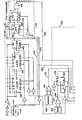
- Fig. 1 illustrates an ink jet printer of the type which may incorporate the present invention.
- the printer has a print head 10 which includes a manifold 12 defining a reservoir 14 to which ink is applied under pressure.
- the ink emerges from orifices 16 defined in orifice plate 18 and breaks up into jet drop streams 20 which are initially directed toward a print receiving medium 22, carried by belt transport 24 past the print head.
- the print head 10 includes an electromechanical transducer (not shown) which stimulates the drop formation of the jet drop streams.
- a piezoelectric transducer may be positioned in the top of reservoir 14 to produce pressure waves which pass downward through the ink and are coupled to each of the jet drop streams.
- the transducer may be arranged to vibrate the entire print head.
- Charge electrodes 26 associated with each of the streams are appropriately positioned adjacent the point of drop formation for selectively charging of the drops as they are formed.
- the charge electrodes may advantageously be defined by notches along the edge of charge plate 28 which are lined with electrical conductive material and electrically connected to individual printed circuit conductors on the top of plate 28.
- a drop catcher 30 is provided for catching the selected ones of the drops which are not to be deposited upon moving print receiving medium 22 as the medium moves beneath the printer.
- a deflection means including electrode 32, catcher 30, and voltage sources 34 and 36, produces an electrostatic field through which the drops pass. This field deflects the drops in dependence upon the electrical charges which they carry such that the drops are directed either to the catcher 30 or into one of the print trajectories 38.
- the catcher 30 includes a body 40 which in conjunction with porous plate 42 defines a suction cavity 44. Any drops which strike plate 42 are ingested into cavity 44 and carried away. Similarly, deflected drops which are caught by lip 46 of catcher 30 are removed by a fluid suction arrangement (not shown).
- deflection electrode 32 includes a body 48 and a porous plate 50 which together define a suction chamber 52. Ink mist which may accumulate on plate 50 is ingested into chamber 52 and carried away by the fluid suction arrangement.
- the potential sources 34 and 36 provide a potential difference between plates 42 and 50 and therefore a deflection field therebetween.
- the print head 10 preferably produces a plurality of jet drop streams arranged in a row normal to the plane of Fig. 1 and skewed with respect to the direction of movement of medium 22.
- the drops in trajectories 38 are deflected in a direction which is inclined with respect to the direction of movement of the medium and which results in the deposit of drops from each jet at positions which are laterally.displaced across the medium and longitidunally displaced along the medium.
- a separate charge electrode driver including a switched amplifier circuit 54 and an AND gate 56, applies print control signals to each of the charge electrodes 26 via line 58, as more fully discussed below.
- the print control signals are provided upon receipt of a print enable pulse on line 60 and, in dependence upon the print control signals, drops are selectively deposited on medium 22.
- the driver provides a signal to electrode 26 upon failure to receive a print enable signal such that drops produced during this time, termed “guard drops", are directed to the catcher 30.
- the present invention provides print enable signal pulses to the charge electrode driver and, further, provides a drop clock signal pulse train to drive the electromechanical transducer at the frequency for which it was designed.
- the print enable signal pulses are provided in synchronism with the drop clock signal pulse train so that the charging signals provided by the charge electrode driver to the charge electrode are properly timed with respect to the break up of successively formed drops.
- a print enable pulse is, however, provided- only after an increment of movement of the print receiving medium 22, such that the drops deposited by the print head 10 on the medium are properly spaced in the direction of movement of the medium.
- the electromechanical transducer is driven at a sufficiently high frequency such that at least two unneeded drops may be discarded as -guard drops between successive print enable pulses.
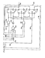
- the circuit includes an oscillator means, preferably a crystal controlled oscillator 110 and a frequency divider circuit 112, which produces a drop clock signal pulse train on line 114 for application via amplifier 116 to the electromechanical transducer which provides stimulation for breakup of the drops.
- the oscillator 110 and frequency divider 112 are selected such that the frequency of the drop clock pulse train is substantially equal to the optimum operational frequency of the transducer. As will become apparent, the higher frequency output from oscillator 110 is used as a system clock for the various circuit components.
- An edge detector means including circuit 118, is responsive to the drop clock signal pulse train on line 122 and provides an edge detection pulse on line 120 upon the occurrence of the leading edge of each drop clock signal pulse.
- a means for providing a synchronization signal on line 124 in dependence upon the speed at which a print receiving medium is transported past the print station includes tachometer 126 and amplifier 128.
- the synchronization signal consists of a train of synchronization pulses on line 124, each such pulse signifying an increment of movement of the print receiving medium.
- the balance of the circuitry defines a state controller means 130 which is responsive to edge detection pulses on line 120 and to the synchronization signal on line 124 to provide print enable pulses on line 60.
- a print enable pulse is produced upon receipt of an edge detection pulse on line 120 next following receipt of a synchronization pulse on line 124.
- the oscillator means includes an oscillator 110 which provides a substantially constant frequency pulse output on line 134 to the counter or frequency divider 112.
- Counters 136 and 138 are connected in tandem so as to provide a pulse train at a reduced frequency to J-K flip-flop 140 which, in turn, provides the drop clock signal pulse train to lines 114, 122, and 142.
- J-K flip-flop 140 which, in turn, provides the drop clock signal pulse train to lines 114, 122, and 142.
- counters 136 and 138 Upon the occurrence of each pulse on line 142, counters 136 and 138 are caused to reload their preset counts.
- Edge detector means 118 includes a pair of D-type flip-flops 144 and 146, with one output from each of the flip-flops coupled to AND gate 148.
- Flip-flops 144 and 146 are clocked by pulses on line 150, which pulses occur at a substantially higher rate than the rate at which drop clock signal pulses are supplied to flip-flop 144 via line 122.
- flip-flop 144 is therefore clocked very quickly such that its Q output goes high. Since, at this point, the /Q output of flip-flop 146 is high, the AND gate 148 provides a high output on line 120, indicating detection of a leading edge of a pulse in the drop clock signal pulse train.
- flip-flop 146 When the next pulse on line 150 occurs, however, flip-flop 146 is set, such that its /Q output goes low, thus causing the output from gate 148 also to go low.
- the duration of a pulse on line 120 is therefore equal to the time period between successive pulses on line 150, regardless of the pulse width of the drop clock signal pulses on line 122.
- the state controller 130 provides a print enable pulse only after receipt of at least two edge detection pulses on line 120 prior to each synchronization pulse on line 124.
- the charge electrode driver is enabled, at the most, only during formation of every third drop and therefore at least two guard drops are produced between successive print drops.
- the state controller 130 comprises three bistable means, J-K flip-flops 152, 154, and 156, and logic means, including gates 158, 160, and 162, and J-K flip-flop latch 164.
- the logic means sequentially actuates the flip-flops 152, 154, and 156 in response to the synchronization signal and the edge detection pulses.
- Flip-flop 154 provides the print enable pulses on line 60 as it repetitively changes states.
- the circuit further includes sensor 166 and amplifier 168 which provide a signal on line 170 to the logic means when a print receiving medium, such as a sheet of copy paper, is present at the print station for printing thereon by the ink jet printer.
- a print receiving medium such as a sheet of copy paper
- the presence of a print receiving medium at the print station for receipt of the ink drops is a necessary condition for the production of a print enable pulse by the controller 130. This prevents ink from inadvertently being deposited on the print receiving medium transport or other printer structure. Such an arrangement may not be necessary, however, when printing is being accomplished on a continuous strip or web of paper.
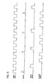
- Fig. 3 is a timing diagram which is useful, in conjunction with Figs. 2a and 2b, in explaining the manner in which the circuit operates.
- Flip-flops 152, 154, and 156 are connected such that they are sequentially set by pulses on line 150, assuming that conditions are correct for enablement in sequence of logic gates 158, 160, and 162.
- flip-flop 154 has just provided a high signal on its Q output, such that a print enable pulse is in the process of being supplied to line 60.
- This high output is also supplied to AND gate 162 via line 172 such that upon the occurrence of the next pulse on line 120, indicating detection of a leading edge of a pulse in the drop clock signal pulse train on line 122, the K input of flip-flop 154 goes high.
- flip-flop 154 This resets flip-flop 154 and simultaneously sets flip flop 156, both occurring upon receipt of a clocking pulse on line 150.
- the Q output of flip-flop 156 therefore goes high, enabling AND gate 158 via line 174 such that, upon the detection of the leading edge of the next successive drop clock signal, flip-flop 156 is reset, while flip-flop 152 is set. Note that sequential actuation of flip-flops 156 and 152 occurs independently of and without regard to whether a synchronizational pulse is received from tachometer 126.
- Flip-flops 152, 154, and 156 now remain in this state, i.e., with flip-flop 152 set and flip-flops 154 and 156 reset, until all of the inputs of NAND gate 160 go high. This occurs upon receipt of a pulse on line 120, indicating a leading edge of a drop clock pulse and a high signal on line 175, indicating that during the previous print enable pulse a synchronization pulse was applied to latch 164 via line 124. Note that when flip-flop 156 was set, the negative going pulse from the /Q output, applied to line 176, caused the latch 164 to be.reset. As a consequence, only a subsequently received synchronization pulse can result in the high signal on line 175 necessary to enable gate - 160.
- drops are continuously formed at the drop rate (the pulse rate on line 114) while, at the most, the charge electrode driver is enabled and a data drop or print drop is formed from each third drop, with the intermediate drops being guard drops.
- the drop rate is slightly greater than three times the synchronization pulse rate, three guard drops will be produced between successive data drops.
- the print drops may be produced in close synchronization with the speed of movement of the print receiving medium, while allowing the electromechanical transducer to be operated continuously at its designed optimum frequency and, further, while providing for at least two guard drops between successive print drops so as to reduce substantially undesired drop-to-drop cross talk.
- the drop rate may be reduced such that it is slightly greater than two times the synchronization pulse rate. It will be understood, however, that this would also require an attendant modification to the state controller 130.
- a print enable pulse on line 60 enables AND gate 56, permitting the output stage of shift register 180, storing a binary "1" or "0", to be coupled to control switching amplifier 54.
- Register 180 has been previously loaded with binary information specifying which of the drops in the associated jet drop stream are to be printed. If a "0" output is coupled to control input 182, the amplifier 54 is switched to its upper switching position. Voltage v 6 is amplified and applied to the associated charge electrode 26, thereby causing the drop then being formed to be charged and deflected to catcher 30. If, on the other hand, a "1" output is coupled to input 182, the amplifier 54 is switched to its lower switching position.
- Register 180 and generator 124 both receive synchronization pulses on line 124. Upon receipt of each such pulse, generator 184 cycles to a different voltage level, and register 180 shifts a new bit of binary information to its output stage for application to amplifier 54 via AND gate 56 when an enabling pulse is received subsequently on line 60. As previously discussed, a synchronization pulse is provided just prior to each print enable pulse.
- the present invention has applicability with respect to ink jet printers of all types in which drop placement accuracy is a significant consideration.
Landscapes
- Particle Formation And Scattering Control In Inkjet Printers (AREA)
Applications Claiming Priority (2)
| Application Number | Priority Date | Filing Date | Title |
|---|---|---|---|
| US392195 | 1982-06-25 | ||
| US06/392,195 US4510503A (en) | 1982-06-25 | 1982-06-25 | Ink jet printer control circuit and method |
Publications (2)
| Publication Number | Publication Date |
|---|---|
| EP0098056A2 true EP0098056A2 (fr) | 1984-01-11 |
| EP0098056A3 EP0098056A3 (fr) | 1985-12-27 |
Family
ID=23549650
Family Applications (1)
| Application Number | Title | Priority Date | Filing Date |
|---|---|---|---|
| EP83303155A Ceased EP0098056A3 (fr) | 1982-06-25 | 1983-06-01 | Circuit de contrôle pour imprimante à jet d'encre et méthode |
Country Status (7)
| Country | Link |
|---|---|
| US (1) | US4510503A (fr) |
| EP (1) | EP0098056A3 (fr) |
| JP (1) | JPS597062A (fr) |
| BR (1) | BR8301558A (fr) |
| CA (1) | CA1201930A (fr) |
| IL (1) | IL67967A (fr) |
| SU (1) | SU1205788A3 (fr) |
Cited By (2)
| Publication number | Priority date | Publication date | Assignee | Title |
|---|---|---|---|---|
| EP0202032A3 (fr) * | 1985-05-09 | 1988-01-20 | Burlington Industries, Inc. | Appareil pour appliquer un jet liquide perturbé artificiellement au hasard, et méthode |
| EP0473179A3 (en) * | 1990-08-31 | 1992-06-17 | Canon Kabushiki Kaisha | Ink jet recording apparatus |
Families Citing this family (11)
| Publication number | Priority date | Publication date | Assignee | Title |
|---|---|---|---|---|
| US4999644A (en) * | 1989-12-18 | 1991-03-12 | Eastman Kodak Company | User selectable drop charge synchronization for traveling wave-stimulated, continuous ink jet printers |
| AU6622296A (en) * | 1995-08-04 | 1997-03-05 | Domino Printing Sciences Plc | Continuous ink-jet printer and method of operation |
| US5801734A (en) * | 1995-12-22 | 1998-09-01 | Scitex Digital Printing, Inc. | Two row flat face charging for high resolution printing |
| TWI403698B (zh) * | 2009-03-03 | 2013-08-01 | Ind Tech Res Inst | 列印信號產生系統與方法 |
| JP4044012B2 (ja) * | 2003-08-29 | 2008-02-06 | シャープ株式会社 | 静電吸引型流体吐出装置 |
| US8491076B2 (en) * | 2004-03-15 | 2013-07-23 | Fujifilm Dimatix, Inc. | Fluid droplet ejection devices and methods |
| US7281778B2 (en) * | 2004-03-15 | 2007-10-16 | Fujifilm Dimatix, Inc. | High frequency droplet ejection device and method |
| EP1836056B1 (fr) | 2004-12-30 | 2018-11-07 | Fujifilm Dimatix, Inc. | Impression a jet d'encre |
| US7273270B2 (en) * | 2005-09-16 | 2007-09-25 | Eastman Kodak Company | Ink jet printing device with improved drop selection control |
| US7988247B2 (en) | 2007-01-11 | 2011-08-02 | Fujifilm Dimatix, Inc. | Ejection of drops having variable drop size from an ink jet printer |
| US8393702B2 (en) * | 2009-12-10 | 2013-03-12 | Fujifilm Corporation | Separation of drive pulses for fluid ejector |
Family Cites Families (10)
| Publication number | Priority date | Publication date | Assignee | Title |
|---|---|---|---|---|
| US3596275A (en) * | 1964-03-25 | 1971-07-27 | Richard G Sweet | Fluid droplet recorder |
| US3588906A (en) * | 1968-10-18 | 1971-06-28 | Mead Corp | Image construction system with clocked information input |
| US3596276A (en) * | 1969-02-10 | 1971-07-27 | Recognition Equipment Inc | Ink jet printer with droplet phase control means |
| US3701998A (en) * | 1971-10-14 | 1972-10-31 | Mead Corp | Twin row drop generator |
| JPS5230333B2 (fr) * | 1973-12-05 | 1977-08-08 | ||
| DE2450063A1 (de) * | 1974-10-22 | 1982-09-23 | Licentia Patent-Verwaltungs-Gmbh, 6000 Frankfurt | Antenne fuer einen elektronischen geschoss-zuender |
| US4012745A (en) * | 1975-11-28 | 1977-03-15 | Burroughs Corporation | Phase correction system |
| US4047085A (en) * | 1976-03-01 | 1977-09-06 | Teletype Corporation | Method and apparatus for controlling a web handling device |
| US4326204A (en) * | 1980-08-25 | 1982-04-20 | The Mead Corporation | Density control system for jet drop applicator |
| US4413265A (en) * | 1982-03-08 | 1983-11-01 | The Mead Corporation | Ink jet printer |
-
1982
- 1982-06-25 US US06/392,195 patent/US4510503A/en not_active Expired - Lifetime
-
1983
- 1983-02-22 IL IL67967A patent/IL67967A/xx unknown
- 1983-02-28 CA CA000422525A patent/CA1201930A/fr not_active Expired
- 1983-03-25 BR BR8301558A patent/BR8301558A/pt unknown
- 1983-03-28 JP JP58052309A patent/JPS597062A/ja active Pending
- 1983-06-01 EP EP83303155A patent/EP0098056A3/fr not_active Ceased
- 1983-06-03 SU SU833599269A patent/SU1205788A3/ru active
Cited By (3)
| Publication number | Priority date | Publication date | Assignee | Title |
|---|---|---|---|---|
| EP0202032A3 (fr) * | 1985-05-09 | 1988-01-20 | Burlington Industries, Inc. | Appareil pour appliquer un jet liquide perturbé artificiellement au hasard, et méthode |
| EP0473179A3 (en) * | 1990-08-31 | 1992-06-17 | Canon Kabushiki Kaisha | Ink jet recording apparatus |
| US5298926A (en) * | 1990-08-31 | 1994-03-29 | Canon Kabushiki Kaisha | Ink jet recording apparatus and method for capturing satellite ink droplets and ink mist |
Also Published As
| Publication number | Publication date |
|---|---|
| IL67967A (en) | 1987-02-27 |
| SU1205788A3 (ru) | 1986-01-15 |
| BR8301558A (pt) | 1984-04-17 |
| IL67967A0 (en) | 1983-06-15 |
| EP0098056A3 (fr) | 1985-12-27 |
| US4510503A (en) | 1985-04-09 |
| CA1201930A (fr) | 1986-03-18 |
| JPS597062A (ja) | 1984-01-14 |
Similar Documents
| Publication | Publication Date | Title |
|---|---|---|
| EP0113499B1 (fr) | Imprimante à jet d'encre | |
| US4510503A (en) | Ink jet printer control circuit and method | |
| US4219822A (en) | Skewed ink jet printer with overlapping print lines | |
| US4274100A (en) | Electrostatic scanning ink jet system | |
| US4122458A (en) | Ink jet printer having plural parallel deflection fields | |
| US3596276A (en) | Ink jet printer with droplet phase control means | |
| CN101610908B (zh) | 喷墨记录装置 | |
| EP0034060A1 (fr) | Imprimante par jet d'encre | |
| US9028024B2 (en) | Binary continuous inkjet printer with a decreased printhead cleaning frequency | |
| DE2541082C3 (de) | Vorrichtung zum Synchronisieren von Tröpfchenbildung und -aufladung bei einem Tintenstrahlschreiber | |
| US3898671A (en) | Ink jet recording | |
| US3864692A (en) | Time dependent deflection control for ink jet printer | |
| JPS5849270A (ja) | インク・ジェット印刷方法 | |
| US4313123A (en) | Controllable ink drop velocity type ink-jet printer | |
| US4314258A (en) | Ink jet printer including external deflection field | |
| US4544930A (en) | Ink jet printer with secondary, cyclically varying deflection field | |
| US6595629B2 (en) | Continuous inkjet printer | |
| US3875574A (en) | Method for improving performance of an ink jet bar code printer | |
| EP0723870A1 (fr) | Impression d'images à échelles de gris par un réseau de jets d'encre à haute résolution | |
| EP0458943B1 (fr) | Synchronisation de la charge de gouttelettes selectionnee par l'utilisateur, pour imprimantes a jet d'encre continu stimule par des ondes progressives | |
| US4015267A (en) | Ink jet printer having air resistance distortion control | |
| JPS6322663A (ja) | インクジェット記録装置及びその制御方法 | |
| CA2193156A1 (fr) | Dispositif de projection d'encre pour impression a haute definition | |
| US4371878A (en) | Device for correcting ink dot misplacement in ink-jet printing | |
| EP0104951A2 (fr) | Imprimante à jet d'encre et procédé d'opération d'imprimante |
Legal Events
| Date | Code | Title | Description |
|---|---|---|---|
| PUAI | Public reference made under article 153(3) epc to a published international application that has entered the european phase |
Free format text: ORIGINAL CODE: 0009012 |
|
| AK | Designated contracting states |
Designated state(s): BE CH DE FR GB IT LI NL SE |
|
| PUAL | Search report despatched |
Free format text: ORIGINAL CODE: 0009013 |
|
| AK | Designated contracting states |
Designated state(s): BE CH DE FR GB IT LI NL SE |
|
| 17P | Request for examination filed |
Effective date: 19860623 |
|
| 17Q | First examination report despatched |
Effective date: 19870923 |
|
| RAP1 | Party data changed (applicant data changed or rights of an application transferred) |
Owner name: EASTMAN KODAK COMPANY |
|
| STAA | Information on the status of an ep patent application or granted ep patent |
Free format text: STATUS: THE APPLICATION HAS BEEN REFUSED |
|
| 18R | Application refused |
Effective date: 19890305 |
|
| RIN1 | Information on inventor provided before grant (corrected) |
Inventor name: MCJOHNSON, ROBERT BAIN Inventor name: PARANJPE, SURESH C. |